4 minute read
INLETFLAMETRAP/FLAMEPROOFJOINTS


Blakefield South FBL-55H Service Manual
INLET FLAME TRAP/FLAMEPROOF JOINTS
The Caterpillar 3126 diesel engine system is approved as a flameproof diesel engine system suitable for use in underground coal mines. The flameproof design allows the engine to be used in the designated hazardous or potentially gassy areas within the mine. The principle of flameproofing the engine system involves designing it to withstand an internal explosion without damaging the structural integrity of the engine components. This ensures that the internal explosion will not propagate to the outside atmosphere with sufficient energy to cause an external explosion. In the case of the air intake system the flameproofing commences at the aftercooler flame trap and proceeds to the intake manifold, engine block gasket.
WARNING This engine system is tested and approved for use in an atmosphere with a maximum methane (CH4 ) concentration of 1% by volume. If higher levels are encountered the machine must be driven immediately to a ventilation intake area within the mine where the methane concentration is less than 1% by volume.
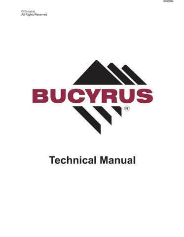
Flame Trap Housing
Blakefield South FBL-55H Service Manual
SERVICING AIR INTAKE SYSTEM
As with other maintenance and examination schedules the flameproof intake system should be inspected, by a suitably appointed and qualified person, at intervals consistent with mine site and statutory maintenance schemes. The following is the suggested intervals for maintenance and inspection of the flameproof air intake components. Daily or every 10 service hours: Visually check joint fasteners (nuts, bolts and studs) securing flameproof joints i.e. flame trap flange to after cooler, and after cooler to cylinder head
NOTICE Refer to the Diesel Engine System approval drawings for flame path dimensions and conditions.
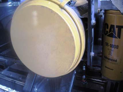
Air Cleaner Assembly Indicator Assembly
Air Intake System
Blakefield South FBL-55H Service Manual
NOTICE! When system has been disassembled and reassembly is complete, check all flameproof joints for integrity using soapy water solution and 0.2 mm feeler gauge.
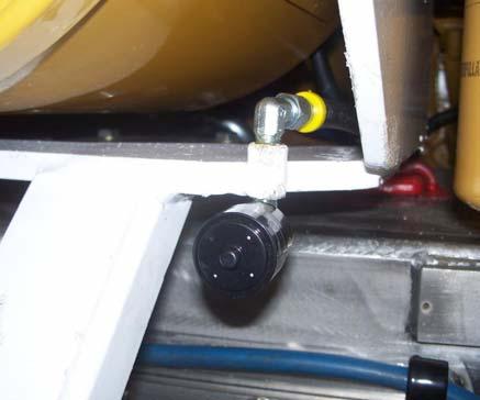
Every 250 service hours: 1) Check tightness of all joint fasteners (nuts, bolts and studs) securing flameproof joints i.e. flame exhaust manifold to engine block, exhaust manifold to turbo, turbo to exhaust downpipe, exhaust downpipe to exhaust conditioner. Use soapy water around joints to check for any leaks. Every 2000 service hours or 2 service years. (Code D): 1) Disassemble all flameproof joint connections clean and inspect for surface finish, flatness, corrosion or damage. Repair as required. 2) Hydrostatically pressure test all exhaust system exhaust and water jacket chambers external to the engine block i.e. exhaust downpipe and purifier. Water jacket Hydrostatic test 250 kPa (35 psi) Gas path Hydrostatic test 1000 kPa (145 psi) 3) After testing and inspection are completed and passed, reassemble using new gaskets and correct torque settings. 4) When reassembly is complete check all flameproof joints for integrity using soapy water solution and 0.2 mm feeler gauge.
See you engineering staff for correct inspection sheets
Blakefield South FBL-55H Service Manual
COOLING SYSTEM
General description
The cooling system performs two prime functions: 1) To effectively dissipate the heat generated by the engine and the engine lubricant during the combustion process. 2) To effectively limit the surface temperature of the engine external components, including exhaust gases, to the maximum allowable limit of 150°C. For the engine cooling, the coolant is drawn from the cool radiator core by the engine water pump and is forced through the oil cooler housing and into the cylinder block. A parallel cooling circuit commencing from the water pump outlet and runs continuously back to the hot core of the radiator. From the cylinder block coolant passes up through the air compressor cylinder head, manifolds, cylinder head and when the engine is at normal operating temperature, through the thermostats and back into the hot core of the radiator. It also flows from the engine water pump to the exhaust conditioner flange through to the downpipe and back to the water pump. Coolant then flows through the radiator where the temperature is lowered by the air stream generated by the radiator fan. Upon starting a cold engine, or when the coolant is below thermostat operating temperature, the coolant flow to the radiator is blocked or restricted by the thermostat. A bypass provides coolant circulation within the engine during this warm up period. A header tank provides top up coolant into the suction side of the water pump and the cold radiator core via gravity feed.
WARNING The cooling system run at a nominal 100 kPa pressure and can reach temperatures of more than 100°C. Release stored pressure and wear personal protective equipment when accessing.
Safety Precautions
The following safety precautions are not intended to be exhaustive. Safe work practices should be used when servicing or operating heavy machinery. ALWAYS give the engine an opportunity to cool down before performing cooling system servicing. ALWAYS wear personal protective equipment including safety glasses, gloves and suitable clothing, particularly when accessing the coolant system. ALWAYS be aware of, and isolate, other forms of energy and pinch points (fan, belts, pulleys) when accessing the engine compartment including pneumatic stored pressure, coolant pressure and other heat sources such as engine block and exhaust system components.