
397 minute read
Dipper Trip - General Arrangement


A single-line automatic lubrication system applies open gear lubricant (OGL) and grease via a programmable logic controller (PLC). The system has six lube pumps (four for OGL and two for grease), each feeding individual PLC controlled circuits. Lincoln Powermaster Four 75:1 air powered pumps are mounted on two reservoirs. High pressure hoses with reusable fittings are utilized.
Lubrication Room
The six separately controlled lube circuits provide selective distribution frequency and quantity resulting in reduced lubricant usage and cost.
FRONT END EQUIPMENT
The front end equipment consists of the boom, the boom point sheaves, padlock, saddle block, dipper handle, dipper, dipper trip mechanisms, running ropes and boom suspension strands.
SUSPENSION STRANDS
The suspension strands are designed to maintain the proper boom angle. These are fixed-length strands that support the entire weight of the boom and the load.
BOOM
The boom is a welded steel structure consisting of twin box girders integrally connected at the boom point and in the lower section between the shipper shaft and boom feet. Impact resistant steel is utilized, coupled with 100% penetration and UT quality welds on all main splice joints. Design optimization has resulted in heavier outside skin plates, minimizing the need for internal diaphragms. This reduction in weld related stress concentrations further enhances structural life. Open manholes have been incorporated in the boom as a standard feature permitting periodic structural inspection. Integral “ladders” within the upper boom sections permit internal access without lowering the boom.
Boom Assembly
The boom is supported by four pre-stressed suspension (structural) strands attached to equalizer links on the A-frame. These inherent long life structural strands carry the working loads of the front end equipment. A boom limit switch with soft setdown prevents boom jacking shock loads.
RUNNING ROPES
Hoist, crowd, retract and dipper trip ropes are all plastic impregnated for increased life and for sheave and drum grooving life enhancement. The double twin hoist ropes are attached to the center of the hoist drum using ferrule-becket anchoring for faster rope change out. Each rope passes over a boom point sheave through the padlock and back over the boom point sheave to the hoist drum. The dual twin hoist rope configuration stabilizes the dipper while digging by attachment to the outer edges of the dipper body.
Ropes - General Arrangement
Crowd and retract ropes are attached to the crowd drum and work as an integral system. As the crowd rope is wound on to the drum, the retract rope is reeled off.
SADDLE BLOCK
The saddle block is positioned between the boom side girders in the mid-section of the boom. It pivots on manganese-bronze bushings about the shipper shaft. It acts as a guide for the longitudinal movement of the dipper handle. The free-floating design of the handle in the saddle block eliminates handle torsion.
DIPPER HANDLE
The dipper is attached to one end of the large diameter handle. The crowd rope half-sheave is attached to the other end. A hydraulic rope take-up mechanism at the dipper end, and the crowd rope adjusting mechanism are used to remove slack from the crowd/retract rope system. The dipper handle crowds out and retracts within the saddle block.
An electrical rate reduction circuit, along with the crowd ropes, absorb digging shock loads encountered when the dipper is crowded into the bank.
DIPPER
A general purpose dipper is usually constructed as a casting and plate weldment. The dipper lip and lower front are alloy heat treated castings. The dipper body, back, upper sides and door are made of steel plate. Removable tooth adapters and replaceable tooth points are attached to the lip casting to penetrate the bank material.
The door is hinged and latched to the dipper body. A dipper trip mechanism controls the release of the latch bar, allowing the door to swing open. The latch bar holds the door shut during digging. Spring loaded snubbers dampen the door’s swinging action.
Dipper Assembly
PADLOCK
Padlocks connect the hoist ropes to the outer edges of the dipper while still permitting fore and aft and sideways movement.
DIPPER TRIP
The dipper trip is a wire rope activated dipper door trip mechanism driven by an electric motor through gear reduction mounted on the boom near the boom foot.
Dipper Trip - General Arrangement
TYPICAL MACHINE SPECIFICATIONS
This specification describes the principal mechanical features of a standard Bucyrus International, Inc. 495HR IGBT Acutrol controlled machine. The machine is fully revolving, crawler mounted and equipped to operate from an alternating current power source.
NOTE: These are typical machine specifications.
Working Weight (w/Dipper) Dipper (60 yd3, 46 m3) Ballast Net Weight, minus Ballast and Dipper
Weights
(pounds) (kilograms)
2,877,000 1,305,000 145,000 65,800 700,000 318,200 1,928,000 874,500
Front End Equipment
Boom
Welded, Impact Resistant Steel Boom Point Sheaves Twin Grooved, Flame Hardened Boom Point Sheave Diameter 96" 243.84cm Shipper Shaft Sheaves Twin Grooved, Flame Hardened Shipper Shaft Sheave Diameter 72" 182.88cm Dipper Handle Diameter 34" 86.36cm Dipper Handle Wall Thickness 3" (nominal) 7.62 cm
Rope Data
Hoist
# Ropes Diameter
Type Constr.
2 2 3/4"69.88mm Twin Dual 6X37
Crowd 1 2 1/2" 63.5mm Single Dual 6X37
Retract
1 2 1/2" 63.5mm Single Dual 6X37 Dipper Trip 1 3/4" 19.1mm Single 6X37 Boom Suspension 4 3 1/4" 82.6mm Equalized Structural Strand
Typical Dimensions and Working Ranges
US
Metric
Dipper Capacity (nominal) .............................................60 yd3 ..................... 46 m3 Dipper Capacities (range) ......................................... 40-80 yd3 .......... 30.6-61.2 m3 Length of Boom ..................................................................67'....................20.4 m Boom Angle.......................................................................43º.........................43º Effective Length of Dipper Handle .................................35’-10"....................10.9 m Overall Length of Dipper Handle......................................47’-0”....................14.3 m A:Dumping Height........................................................33’-0".................. 10.05 m A1:Dumping Height at Maximum Radius .......................28’-3"....................8.61 m B:Dumping Radius - Maximum ....................................71’-0".................. 21.64 m C:Cutting Height - Maximum........................................60’-3".................. 18.02 m D:Cutting Radius - Maximum .......................................82’-0".................. 25.00 m E:Radius of Level Floor .............................................. 52’-11”.................. 16.11 m G:Clearance Height @ Boom Point Sheaves................68’-0".................. 20.72 m H:Clearance Radius @ Boom Point Sheaves ...............64’-9”.................. 19.74 m I: Clearance Radius @ Revolving Frame .................... 29’-11"....................9.12 m J:Clearance - Revolving Frame to Ground ..................11’-11"....................3.63 m K:Height of A-Frame....................................................45’-7".................. 13.89 m N:Operator’s Cab Eye Level .........................................30’-0"....................9.14 m
H D
BUCYRUS
K
J
I
495HR
N
E
B
A1 A C G
COMPONENT WEIGHTS
Quantity Weight Each
(U.S. Pounds)
Lower Works
Truck Frame................................................1...........191,430 Pintle Bushing .............................................1..................280 Lower Rail...................................................9..................570 Thrust Rail...................................................9..................170 Propel Brake Adapter.................................2..................370 Propel Brake..............................................2..................650 Propel Brake Hub.......................................2....................60 Propel Motor ...............................................2...............4,500 Propel Motor Blower...................................2..................210 Propel Motor Guard ....................................2....................60 Crawler Belt (47 shoes)...............................2...........123,280 Crawler Link (78.75”) .................................47..............2,480 Crawler Assembly~Shipping .......................2...........129,730 Crawler Assembly~Mechanical ...................2...........129,530 Crawler Structure ........................................2.............77,650 Propel Gearcase........................................2.............15,850 Front Idler....................................................2...............5,800 Shaft, Front Idler..........................................2...............1,150 Adjusting Block ...........................................4..................370 Load Roller .................................................8...............2,020 Shaft, Load Roller .......................................8..................550 Rear Idler ....................................................2...............3,800 Shaft, Rear Idler ..........................................2..................700 Tumbler,Drive..............................................2...............7,120 Shaft, Drive Assy.........................................2...............4,330 Shaft, Drive .................................................1...............3,370 Sleeve, Center Pintle ..................................1...............9,100 Collar, Center Pintle, Upper.........................1..................380 Nut, Lock, Assy, Center Pintle.....................1...............1,480
Quantity Weight Each
(U.S. Pounds)
Upper Works
A-Frame Front Leg.....................................1..............23,000 A-Frame Rear Leg......................................2................6,650 Auxiliary Winch Assembly............................2................2,350 Boom Foot Pin............................................2...................550 Upper Rail...................................................10.................500 Swing Planetary Gearcase..........................2..............10,600 Swing Pinion Shaft Assembly......................4................1,990 Swing Pinion Shaft......................................4................1,460 Swing Bearing Carrier ................................4...................230 Swing Shaft Bearing...................................4...................100 Swing Brake Adapter..................................2...................270 Swing Brake...............................................2...................490 Swing Motor (w/o Tach) ...............................1................4,500 Swing Motor (w/ Tach) .................................1................3,600 Crowd 2nd Intermediate Shaft .....................1................2,000 Crowd 2nd Intermediate Gear .....................1................2,640 Crowd Motor Shaft Coupling .......................1...................150 Crowd Frame..............................................1..............11,500 Crowd Pinion Guard....................................1...................280 Crowd Gearcase Cover ..............................1................2,700 Crowd Upper Gear Guard ...........................1...................170 Crowd Gear Guard - Lower .........................1...................340 Crowd Drum ...............................................1..............12,800 Crowd Drum Spur Gear...............................1................4,970 Crowd 1st Intermediate Shaft ......................1...................130 Crowd 1st Intermediate Gear ......................1................1,080 Crowd Brake..............................................1...................500 Crowd Brake Adapter.................................1...................270 Crowd Motor ...............................................1................4,000 Air Swivel....................................................1...................150 Collector Ring Assembly .............................1...................230 Housing, Front ............................................1...................150 Housing, Rear .............................................1...................150 Hoist Planetary Gearcase ...........................1..............35,500 Hoist Pinion ................................................2................1,650 Hoist Pinion Bearing Carrier .......................2...................460
Quantity Weight Each
(U.S. Pounds)
Upper Works (Cont.) Hoist Machinery Guard - Bottom..................1................2,000 Hoist Machinery Guard - Rear .....................1...................940 Hoist Machinery Guard - Front.....................1................1,300 Hoist Bearing Housing ................................2................3,200 Hoist Drum..................................................1..............30,700 Hoist Spider................................................1..............16,000 Hoist Drum Gear.........................................1..............11,000 Hoist Frame - R. H. .....................................1................8,400 Hoist Oil Cooler ..........................................1................2,650 Hoist Motor .................................................1..............15,000 Hoist Brake.................................................1................1,350 Hoist Brake Adapter....................................1...................500 Hoist Brake Hub..........................................1...................210 Hoist Motor Coupling Shaft Assembly..........1................1,440 Coupling Shaft, Gearcase.......................1...................940 Coupling, Motor.......................................1...................600 Hoist Motor Coupling Guard - Gearcase......1...................150 Hoist Motor Coupling Guard - Motor............1...................100 Boarding Stairs...........................................1................4,100 Machinery House Filter Assembly................2................1,330 Control Room Filter Assembly - Tenkay .......1................7,500 Revolving Frame.........................................1............166,750
Front End
Boom (Bare)...............................................1............138,500 Boom Bumper Assembly.............................8.....................30 Boom Point Sheave Assembly ....................1................6,800 Boom Point Shaft........................................2................1,050 Boom Point Sheave ....................................2................4,230 Saddle Block & Liner Assembly..................1..............25,010 Liner, Saddle Block.....................................2................1,300 Bushing, Saddle Block/Shipper Shaft..........2...................100 Collar, Shipper Shaft...................................2...................120 Shipper Shaft..............................................2................4,880 Shipper Shaft Assembly ..............................1................5,110 Crowd / Retract Rope .................................2................2,100
Quantity Weight Each
(U.S. Pounds)
Front End (Cont.) Hoist Rope..................................................1 pair.......10,400 Suspension Rope .......................................4................2,750 Pendant Equalizer - R.H. .............................1................2,400 Pendant Equalizer - L.H. .............................1................2,400 Handle Weldment........................................1.............48,700 Crowd Take-Up Shop Assy .........................1.............10,300 Crowd Take-Up Guide .............................1...............2,200 Crowd Take-Up Worm Gear....................1..................610 Crowd Take-Up Gear Housing.................1..................440 Crowd Take-Up Screw Rod.....................1...............4,520 Crowd Half-Sheave.................................1...............1,920 Retract Take-Up Cylinder ............................2..................150 Retract Take-Up Guide................................1..................500 Retract Spreader and Stop..........................1...............2,100 Crowd Sheave ............................................2...............2,600
Dipper Assembly:
Complete Dipper w/ Liners.........................1...........164,550 Includes:.......................................................................... Dipper Body with Liners..........................1...........109,810 Latch Bar................................................1...............1,180 Latch Lever.............................................1..................500 Snubbers................................................2...............1,750 Pitch Brace.............................................2...............3,340 Center Shroud.........................................8..................500 Corner Shroud.........................................4..................300
Section 2 Operation
Always refer to the safety information in Section 1 of this manual before starting any maintenance procedure on this machine.
Table of Contents
GENERAL INFORMATION ............................................................................................................5 OPERATION NEAR ELECTRICAL LINES...............................................................................5 OPERATOR’S CONTROLS .........................................................................................................7 PRIMARY OPERATING CONTROLS.....................................................................................7 CONTROLS ON THE LEFT CONSOLE...........................................................................8 LEFT MASTER SWITCH.............................................................................................8 DIPPER TRIP..............................................................................................................8 SIGNAL HORN.............................................................................................................8 Left Control Console ...................................................................................................................9 START PUSHBUTTON.............................................................................................10 PLC POWER ON......................................................................................................10 DRIVE CABINET TEMPERATURE............................................................................10 INCOMPLETE SEQUENCE......................................................................................10 SYSTEM READY.......................................................................................................10 PHASE SEQUENCE.................................................................................................10 AUXILIARY GROUND FAULT ....................................................................................10 HOIST BRAKE..........................................................................................................11 CROWD BRAKE ......................................................................................................11 SWING BRAKE.........................................................................................................11 PROPEL BRAKE......................................................................................................11 HVAC UNIT SELECTOR...........................................................................................11 TEMPERATURE........................................................................................................11 HVAC SYSTEM CONTROL.......................................................................................11 HVAC FAN SPEED....................................................................................................11 AUXILIARY HEATER..................................................................................................11 CONTROLS ON THE RIGHT CONSOLE.......................................................................12 RIGHT MASTER SWITCH.........................................................................................12 Right Control Console ................................................................................................................13 EMERGENCY STOP PUSHBUTTON.......................................................................14 WINDSHIELD WIPER SWITCHES...........................................................................14 CONTROL STOP PUSHBUTTON............................................................................14 CONTROL RESET PUSHBUTTON..........................................................................14 AIR COMPRESSOR.................................................................................................15
DIG/PROPEL TRANSFER SWITCH...............................................................................15 HEATED MIRRORS..................................................................................................15 MAIN POWER OFF PUSHBUTTON.........................................................................15 MAN ON GROUND....................................................................................................16 EARTH CONTINUITY LOCKOUT PUSHBUTTON....................................................16 SEAT POSITION.......................................................................................................16 RADIO/CASSETTE/CD.............................................................................................16 OPERATOR’S DISPLAY.............................................................................................................17 DISPLAY AREA AND INDICATORS .......................................................................................17 DISPLAY SCREENS.............................................................................................................18 Title Screen ...............................................................................................................................18 Main Menu .................................................................................................................................19 Main Menu - Info ........................................................................................................................19 Active Alarm ..............................................................................................................................20 New Alarm .................................................................................................................................20 Alarms Help ...............................................................................................................................21 Rope Reeving/Pintle Tightening..................................................................................................22 Rope Reeving/Pintle Tightening Help..........................................................................................23 Calibration Help.........................................................................................................................24 Fault Counters/Operating Hours .................................................................................................25 PLC Menu Screen ......................................................................................................................25 Typical Bearing Temperature Screen ..........................................................................................26 Operator’s Screen ......................................................................................................................26 BRAKE INDICATORS.....................................................................................................27 TIME/DATE WINDOW.....................................................................................................27 CONTROL STATUS INDICATORS..................................................................................28 LIMIT SLOWDOWN INDICATORS..................................................................................28 DIG/PROPEL INDICATOR..............................................................................................28 INFORMATIONAL ICONS ................................................................................................29 DELAYED SHUTDOWN INDICATOR.............................................................................29 ACTIVE ALARMS INDICATOR.........................................................................................29 AIR PRESSURE..............................................................................................................29 LUBRICATION CONTROL PANEL........................................................................................30 FIRE SUPPRESSION SYSTEM............................................................................................30 CABLE REEL OPERATION........................................................................................................31 PRE-START CHECKS................................................................................................................32 WALK-AROUND GROUND LEVEL INSPECTION................................................................32
ON-BOARD INSPECTION....................................................................................................34 START-UP, OPERATION AND SHUTDOWN.............................................................................35 MACHINE START-UP ............................................................................................................35 RESTARTING AFTER AN ELECTRICAL FAULT ...................................................................36 MACHINE OPERATION.........................................................................................................37 MACHINERY MOTIONS ........................................................................................................38 HOIST MOTION...............................................................................................................38 CROWD MOTION...........................................................................................................39 PROPEL MOTION...........................................................................................................40 Propel - Straight Forward/Reverse .............................................................................................40 SWING MOTION .............................................................................................................41 PROPER SWING MOTION.......................................................................................42 STEERING ......................................................................................................................43 COUNTER-ROTATION TURNS................................................................................45 POSITIONING THE MACHINE.........................................................................................46 BACK-UP METHOD..................................................................................................46 DRIVE-BY METHOD .................................................................................................47 START OF THE DIG CYCLE..........................................................................................48 Force the Dipper Lip into the Bank.............................................................................................48 Variations on Dipper Penetration ................................................................................................49 Dig with the Dipper Beneath the Boom Point ..............................................................................50 ENGAGING THE BANK ...................................................................................................50 SLOPE LIMITATIONS ......................................................................................................52 Slope vs. Degrees ......................................................................................................................52 Rollover and Operation Limits.....................................................................................................53 EXCAVATED MATERIAL ........................................................................................................53 OPERATION CHECKS.........................................................................................................54 OPERATING HINTS ..............................................................................................................55 STOPPING THE MACHINE ...................................................................................................56 SHUTDOWN.........................................................................................................................56
Section 2 Operation
GENERAL INFORMATION
This section of the manual will assist in the operation of this machine. It provides the operator with the location and explanation of the controls, instructions for machine operation and certain maneuvering techniques. Throughout this section and the remainder of the manual, the use of the terms “LEFT, RIGHT, FRONT and REAR” refer to machine locations as viewed by the operator sitting in the operator’s seat in the cab.
Safe operation of the machine minimizes production delays and costly damage to equipment. Carefully study and follow all recommended procedures in this manual. Safety guidelines are intended to prevent accidents from occurring and are provided in the interest of all mine personnel. Overall safety depends upon the use of good judgment and the alertness of the entire mining crew. Refer to Section 1 in this manual for specific safety precautions.
OPERATION NEAR ELECTRICAL LINES
DANGER: HIGH VOLTAGE! The following precautions shall be complied with whenever operating around or near electrical distribution and transmission lines.
Working in the vicinity of electrical power lines presents a very serious hazard and special precautions must be taken. For purposes of this manual we are considering the entire machine or its load, in any position, that can reach to within the minimum distance specified by local, state and federal regulations.
Safe operating practices require that you maintain the maximum possible distance from the lines and never violate the minimum clearances.
Before working in the vicinity of power lines, always take the following precautions:
• Always contact the owners of the power lines or the nearest electric utility before beginning work.
• You and the electrical utility representative must jointly determine what specific precautions must be taken to insure safety. • It is the responsibility of the user and the electric utility to see that necessary precautions are taken.
• Consider all lines to be power lines and treat all power lines as energized even though it is known that the power is shut off and the line is visibly grounded. • Slow down the operating cycle. Reaction time may be too slow and distances may be misjudged. • Caution all ground personnel to stand clear of the machine at all times. • Use a signal person to guide the machine into close quarters. The sole responsibility of the signal person is to observe the approach of the machine to the power line. The signal person must be in direct communication with the operator and the operator must pay close attention to the signals.
DANGER: HIGH VOLTAGE! Death or injury could result should any part of the machine approach the minimum distance of an energized power line specified by local, state and federal regulations.
OPERATOR’S CONTROLS
The operator must become familiar with the machine and its operating controls before operating the machine.
The operating controls will be grouped as primary and secondary controls, depending upon their location. The primary controls are the controls located in the operator’s cab and the secondary controls are the controls located in the machinery house.
The descriptions listed should familiarize the operator with each control’s location and functional use. The terms left, right, forward and reverse indicate directions with the operator seated in the cab and facing forward, and with the boom extending over the front of the crawlers.
PRIMARY OPERATING CONTROLS
CONTROLS ON THE LEFT CONSOLE
LEFT MASTER SWITCH
The Left Joystick functions as the crowd/horn/dipper trip/propel master switch. It is the vertical handle mounted on the left console of the operator’s seat. The switch will spring return to neutral when released.
During normal operation, pushing the joystick forward will extend the dipper handle and dipper into the bank. Pulling the joystick rearward will retract the dipper handle and dipper toward the machine. The neutral position between the crowd and retract functions is defined by a detent that is easily felt. The rate of motion is controlled by varying the distance the joystick is moved from the neutral (center) position. Full forward or full rearward position provides maximum speed to the handle. Moving the joystick to neutral will cause a braking action slowing the crowding or retracting handle. Reversing the joystick will cause the motion to stop and if the joystick is held in this position, it will change the direction of the motion.
With the propel transfer switch in the PROPEL position, pushing the joystick forward will cause the left crawler to move forward. Pulling the joystick to the rear will cause the left crawler to move in the reverse direction. The crowd/retract motion is locked out electrically when the machine is in the propel mode.
DIPPER TRIP
The dipper trip is part of the crowd joystick function. Moving the joystick to the right will activate the dipper trip mechanism which releases the dipper door latch. The dipper trip is operational throughout the entire range of the crowd motion.
SIGNAL HORN
Moving the joystick to the left will activate the signal horn. The signal horn is operational throughout the entire movement range of the crowd motion.
Left Control Console
START PUSHBUTTON
A pushbutton that, when pressed, will power up the drive system. The system ready light will go out.
PLC POWER ON
A green light that indicates the status of the PLC.
DRIVE CABINET TEMPERATURE
A green light that indicates temperature in the drive cabinet is neither too low nor too high.
INCOMPLETE SEQUENCE
A red light that indicates an incomplete sequence of startup events.
SYSTEM READY
A green light that indicates that the drive system is ready to start, but not yet started.
PHASE SEQUENCE
A green light that indicates that the phase sequence is okay in the incoming power.
AUXILIARY GROUND FAULT
A green light that when lit, indicates that no auxiliary power ground fault exists. If the light is off, alert an electrician as soon as possible.
HOIST BRAKE
A selector switch used to set or release the Hoist Brake.
CROWD BRAKE
A selector switch used to set or release the Crowd Brake.
SWING BRAKE
A selector switch used to set or release the Swing Brake.
PROPEL BRAKE
A selector switch used to set or release the Propel Brake.
HVAC UNIT SELECTOR
A 3-position selector switch used to select air conditioner unit No.1, No. 2, or off.
TEMPERATURE
A rheostat used to control the temperature in the operator’s cab relative to the selected mode of operation.
HVAC SYSTEM CONTROL
A 4-position selector switch used to select the HVAC system mode of operation.
HVAC FAN SPEED
A 3-position selector switch used to control the volume of air moved by the system.
AUXILIARY HEATER
A 3-position selector switch used to control the auxiliary heater.
CONTROLS ON THE RIGHT CONSOLE
RIGHT MASTER SWITCH
The Right Joystick functions as the hoist/swing/propel master switch. It is a joystick mounted on the right console of the operator’s seat. The joystick is used to control the hoist, swing and right crawler motions of the machine. The position of the propel transfer switch will determine whether this switch controls the hoist motion or the crawler motion.
With the propel transfer switch in the dig position, pushing the joystick forward will lower the dipper. Pulling the joystick to the rear will hoist the dipper. The neutral position between the hoist and lower functions is defined by a detent that is easily felt. The speed of moving the dipper is controlled by varying the distance the joystick is moved from the neutral (center) position. The full forward, or full rearward position provides maximum speed to the dipper. Moving the joystick to neutral will cause a braking action slowing the hoisting or lowering motion. Reversing the joystick will cause the motion to stop and if the joystick is held in this position, it will change the direction of the motion.
NOTE: When the hoist/swing master switch is used in the hoist/ lower mode the switch is a spring returned switch. That is, it will return to the neutral position when it is released. Moving the joystick to the left from the neutral position will cause the machine to swing to the left. Moving the joystick to the right will cause the machine to rotate to the right. The swing motion is operational throughout the entire movement range of hoisting or lowering the dipper. The swing rate of acceleration is controlled by varying the distance the joystick is moved from the neutral position. Moving the joystick to the neutral position will not stop the swing motion but will allow the machine to coast. To stop or change direction the control joystick is moved past the neutral point in the opposite direction. The rate of deceleration is controlled by varying the distance the joystick is moved from the neutral position in the opposite direction.
With the propel transfer switch in the propel position, pushing the lever forward will cause the right crawler to move forward. Pulling the lever to the rear will cause the right crawler to move in the reverse direction. The hoist motion is locked out electrically when the machine is in the propel mode.
NOTE: When the JOYSTICK is used in the swing mode the switch is a spring returned switch. That is, it will return to the neutral position when it is released.
Right Control Console
EMERGENCY STOP PUSHBUTTON
The machine stop/emergency stop pushbutton is located on the right operator’s console. It is used to remove power from the machine motions after the motions have been stopped in the normal manner. A second purpose of the pushbutton is to stop the machine under operational emergency conditions. Pushing this button will provide electrical and immediate mechanical braking simultaneously. Therefore, this button should only be used if the operator intends the harshest braking of all motions. If the machine is in motion, power will remain on the motions in order to provide electrical braking for a few seconds. If the machine is in motion or stopped, this button will power the DC bus to approximately zero voltage quickly after the time delay.
CAUTION: PRESSING THIS BUTTON WHEN ANY DRIVE IS IN MOTION MAY RESULT IN COMPONENT DAMAGE.
WINDSHIELD WIPER SWITCHES
The windshield wiper switches control the starting and stopping as well as the speed of the windshield wipers.
CONTROL STOP PUSHBUTTON
The control stop pushbutton is a pushbutton located on the right operator’s console. Normally it is used to de-energize controls after the machine has been safely stopped by placing motion controls in neutral.
CONTROL RESET PUSHBUTTON
CAUTION: This is not an automatic reset system. All controls must be returned to neutral before the control reset button is pushed.
The control reset pushbutton is a pushbutton located on the right operator’s console. The reset pushbutton restores control to all motions if no additional faults exist. This pushbutton is inoperative until the main power start control has been actuated.
If a control fault occurs that shuts down a motion, all motions will automatically be shut down together. At this time the operator should set all brakes. If the fault clears, the motion may be reset by pressing this pushbutton. If the fault does not clear, the unfaulted motions can be restarted by pressing this pushbutton to enable these motions to reposition themselves.
AIR COMPRESSOR
A 3-position selector switch use to select either compressor No.1, No.2 or off.
DIG/PROPEL TRANSFER SWITCH
The Dig/Propel Transfer Switch is used to switch between the two primary operating modes of the machine. The current mode of operation will be indicated on the Operator’s screen on the Operator’s Display.
IMPORTANT: •WHILE IN THE DIG MODE, THE PROPEL CONTROLS ARE DISABLED. •WHILE IN THE PROPEL MODE, THE DIG CONTROLS ARE DISABLED.
The recommended procedure to transfer from hoist to propel is to bring all motions to a controlled stop by the operator. Turn the hoist brake switch to the SET position and then press the control stop pushbutton. Turn the transfer switch from DIG to PROPEL.When the indicator on the Operator Display screen indicates that the transfer has been completed, turn the propel brake switch to release.
HEATED MIRRORS
The heated mirrors switch is a 2-position switch located on the right control console. It is used to activate the heating mechanism in the operator’s cab outside mirrors.
MAIN POWER OFF PUSHBUTTON
The main power off pushbutton is located on the right operator’s console. It is used only to immediately remove power from the drives in case of an electrical emergency involving component failure or fire.
CAUTION: PUSHING THE “POWER OFF” PUSHBUTTON WHILE IN MOTION WILL IMMEDIATELY SET THE MECHANICAL BRAKES AND REMOVE INCOMING HIGH VOLTAGE FROM THE DRIVES. THIS ACTION MAY RESULT IN COMPONENT DAMAGE. It will also result in the inability to power the DC bus voltage down to a low value. This voltage will decay slowly, taking several minutes.
MAN ON GROUND
A 2-position switch that when set to ON will illuminate a light on the roof of the operator’s cab. Use this switch to alert other equipment in the area that a person is on the ground in the vicinity of the machine.
EARTH CONTINUITY LOCKOUT PUSHBUTTON
The earth continuity lockout pushbutton is used to trip the breaker that supplies power to the machine. When the machine is operating, this pushbutton should be used to shutdown the machine only when removal of power to the machine is required.
Actuation of this pushbutton when motions are running will cause all motions to automatically electrically brake to a stop and, when the motion speed has reached less than 5% speed, set all mechanical brakes. If the motions are already stopped, the brakes will be set and power is removed immediately. A similar switch is located on the front panel of the PLC control cabinet that can be used during testing of the machine.
DANGER:THE OPERATOR SHOULD NEVER LEAVE THE OPERATOR’S SEAT BEFORE PRESSING THE CONTROL STOP PUSHBUTTON. Setting only the mechanical brakes with individual switches in not a sufficient safeguard to prevent machine damage and/or personnel hazards.
SEAT POSITION
A selector switch used to move the operator’s seat and consoles forward or back. The seat will continue to move as long as the switch is held, or until the end of the seat’s travel is reached.
RADIO/CASSETTE/CD
A quality AM/FM Radio with cassette and CD player for the operator’s use and connected to speakers in the operator’s cab.
OPERATOR’S DISPLAY
The Operator’s Display is a CTR panel used to provide the operator with an interface to the machine and it’s functional areas. From this informational display the operator can make inputs that effect machine operation, monitor systems and make system adjustments. Through this display terminal the operator will receive pertinent fault data to identify potential problems and prevent machine damage.
The display panel is mounted on a tilt-swivel bracket on the left side of the operator. Individual operators can position the screen in any desired position.
DISPLAY AREA AND INDICATORS
The display area of the monitor screen is the large area in the center of the screen. This area is “touch sensitive.” All information will be displayed on this area in either a text format or in the form of visual icons. The buttons and icons that appear on the screen will respond to touching the screen in the appropriate area of the icon.
These icons and buttons will react by activating the screen, switch activation or display information relevant to the icon. The switches and buttons will be covered in the following pages under the screen topic in which they appear.
The indicators on the lower portion of the screen area are indicators and sensors which indicate functionality of the operator display and it’s interface with the machine’s PLC controller. They have no effect on machine operational use.
All the machine controls can be found on the Operator’s Display Panel touch sensitive screen or the left and right Control Consoles of the operator’s seat.
DISPLAY SCREENS
The Title Screen display appears when the machine is initially started.
Title Screen
The information provided in the central area of the screen is machine specific and lists the machine serial number, the customer name and a listing of important documents and drawings associated with the machine.
The 2 buttons available, if touched, will cause the display to refresh with the information of the desired screen.
Main Menu
The Main Menu screen will provide the operator with a choice of 16 buttons to select. Touching the screen in any of these button areas will cause the display to change to the requested option. Many of these screens will be displayed in the following pages. Several screens have an INFO button which will provide more detailed information concerning the functionality of listed buttons and switches.
Main Menu - Info
The Main Menu Information screen provides information about the various display screen options available through the Main Menu screen.
Active Alarm
The Active Alarm screen will provide a list of all active alarms and faults that have been initiated on the machine and have not been RESET. Once an alarm or fault has been sensed, these messages will remain visible and WILL NOT be removed from this screen until it is RESET.
New Alarm
The New Alarm screen appears automatically any time a machine sensor detects a newly occurring fault or warning message. This screen has the ability to list up to 10 of the new fault messages that
have occurred. If more than 10 new fault messages are present a message will appear below the white text box indicating that more messages are present.
NOTE: It is important to remember that messages will appear in this screen that are no longer active alarm messages. All messages will appear since the time of the last reset.
Alarms Help
The Alarms Help screen can be reached from any of the alarm message screens at any time. This screen will provide clarifying information related to the alarm system on your machine.
Rope Reeving/Pintle Tightening
The Rope Reeving/Pintle tightening screen is selected in order to make adjustments to the center pintle or change any of the main machine wire ropes. This screen will become active in the pintle tightening mode. If rope reeving is the desired intent, a selection must be made at the buttons in the lower left of the display area.
NOTE: Before switching between different modes of operation the Disable Selected Mode button should be pressed.
Switches for the activation/release of the hoist, crowd and swing brakes are provided, along with condition indicators displayed below the brake switches. This screen assists in the correct wrapping of the ropes on drums and allows full control of drum movements.
Rope Reeving/Pintle Tightening Help
This screen will provide clarifying information on the reeving of ropes and pintle tightening.
Calibration
The Calibration screen is used to set the various limits required to control the movements of the machine.
On this screen can be found switches for the hoist, crowd and swing brakes along with status indicators for each.
The limit settings can be found on the left side of the display area.
The white text box near the bottom of the display area displays the current positions of the components.
Calibration Help
This screen will provide clarifying information on the calibration process.
Fault Counters/Operating Hours
The Fault Counter/Operating Hours screen provides the operator with information on the number of faults that have occurred since last RESET. It also provides the total operating hours.
PLC Menu Screen
This screen will active further screens which are used to monitor various racks within the PLC cabinets.
Typical Bearing Temperature Screen
Operator’s Screen
The Operator’s Screen is the primary operational information tool to be visible to the machine operator during daily use of this machine. The controls available on this screen will provide the operator with the information needed to view “at a glance” the status of items required for digging and make changes in control settings.
BRAKE INDICATORS
The 4 rectangular areas in the upper left portion of the operator’s screen provide DISPLAY ONLY information on the motion brakes. The HOIST, CROWD, SWING and the PROPEL brakes are separately identified at this location.
NOTE: The hoist, CROWD AND SWING brakes ARE not to be used as a braking device, except as a holding brake or with an electrical fault or in an emergency. The primary function of the brake is to prevent motor rotation while the particular function is not in use.
1. SET - This will indicate a condition where the brake for that system is fully set and functional as a braking device to prevent movement of that system.
2. SETTING - This message indicates that the brake is in a transition period between the RELEASED and the SET positions. During this period the brake is not functional and care should be exercised to not rely on the brake at this time.
3. RELEASED - This message is an indication that the brake is fully released for the system in question.
4. RELEASING - This is an indication that the brake is in a transition phase from the Set position and has not yet achieved the fully RELEASED position.
NOTE: While in transition from one setting to another (ie: during the RELEASING and SETTING periods, the button will be displayed in yellow. While fully SET or fully RELEASED the button will be displayed in grey.
NOTE: Unlike the other brakes on the machine, the propel brakes are intended as operational brakes and are used in the operation of the machine
TIME/DATE WINDOW
The Time/Date window, locate in the lower left corner of the screen will provide the current local time and date information to the operator at all times. In addition, the total operating hours on the machine will also be displayed.
CONTROL STATUS INDICATORS
The Control Status indicator buttons provide an immediate visual notification of which control systems are functional at that moment. When a control system is active it will be illuminated in green. If a control indicator is grey the system control for that function is currently disabled.
The Dig/Propel switch will have an effect on the status indicators and controls by automatically disabling the propel controls when the machine is in the Dig Mode of operation. Likewise the Hoist, Crowd and Swing controls are automatically disabled when the machine is in the Propel Mode.
It is important to remember that when a brake system is SET the controls for that motion will be disabled.
LIMIT SLOWDOWN INDICATORS
The Limit Slowdown indicators are provided on the operator’s screen to provide the operator with an indication that he is reaching the limits of either the Hoist or the Crowd ropes. These indicators, normally grey, will illuminate yellow as the motion extends into the limit area and the machine has signaled a slowdown condition.
The operator will notice that the reaction of the machine will actually slow down in an effort to prevent damage to the machine by exceeding limits.
The actual settings for these limits is made on the Calibration screen.
DIG/PROPEL INDICATOR
This icon will indicate the current operating mode of the machine by an illumination of the active control in red. To activate the other operating mode, use the Dig-Propel Transfer switch on the operator’s console.
INFORMATIONAL ICONS
The below listed icons are for informational display during the operational use of the machine. These icons will normally be displayed in grey unless the message within the icon is active, and the icon will illuminate yellow.
POWER OFF - Get information from ELECTRICAL.
SYSTEM ON - Get information from ELECTRICAL.
MASTER SWITCH NEUTRAL - Get information from ELECTRICAL.
BOOM JACK LIMIT - This message indicates that the boom is being jacked upward by the crowd motion into the bank. Power is removed from the crowd controls during this event. Pressure must be relieved from the crowd system for controls to return to normal.
FANS OFF - Get information from ELECTRICAL.
LADDER DOWN - This icon displays a message indicating that the boarding ladder is NOT currently stowed in it’s topmost position.
DELAYED SHUTDOWN INDICATOR
The Delayed Shutdown indicator will normally appear as a grey button near the right side of the screen. This indicator will illuminate red when a delayed shutdown fault has occurred and the machine is now in the delay process.
This is a direct indication to the operator that the machine is about to automatically shut down and he must make preparations.
When this illuminates the operator should stop any swing motion and safely place the dipper on the ground in preparation to lose control in one or more machine systems.
ACTIVE ALARMS INDICATOR
The Active Alarms indicator will illuminate red, from grey, whenever there exists a condition in which an active alarm is being signalled from a machine sensor. This indicator will remain red at any time that any active alarm condition exists.
AIR PRESSURE
The air pressure gauge is located on the right portion of the Operator Display. It indicates the regulated air pressure available in the air system.
LUBRICATION CONTROL PANEL
The top row on this panel consists of a group of indicating lights. A red light indicating that the system has a fault and a green light indicating that power for the system is provided for each independent lubricating system (A, B & C). Isolating switches are used to provide power to each system and a means of isolating each system from electrical power. They are also used to reset lubrication faults. These switches are normally on. Manual lube buttons are also provided.
FIRE SUPPRESSION SYSTEM
Fires on surface mining equipment typically involve faults in electrical equipment, or the combustion of flammable fluids. The time between the onset of the fire and its detection is critical. Early detection and suppression of a fire minimizes hazards to personnel, equipment damage, downtime and loss of production. The optional fire suppression system on this machine is supplied and installed by an outside source. Please refer to the system’s manufacturer for maintenance and parts information.
CABLE REEL OPERATION
The cable reel is designed to pick up trail cable as the machine moves toward its power source. It is not designed to drag the trail cable over the ground. The “line pull” of the cable is proportional to operating pressure. The correct line pull is when there is sufficient pull on the cable to wind it on the reel but not too great to put unnecessary strain on the trail cable.
The “line speed” is dependent on the volume of hydraulic oil flowing through the system. The correct line speed is slightly faster than the travel speed of the machine. NOTE: Swing the Control Valve Boom to its fully extended position to allow the cable reel operator to remian in visual contact with the machine operator. To operate the cable reel proceed as follows: 1. If the machine is so equipped, verify that the cable reel “On/Off” switch in the operator’s cab is in the “On” position. 2. Jog the start/stop pushbutton at the cable reel to check for proper rotation of the pump. 3. Start the pump and allow oil to circulate for five minutes. 4. The cable reel, if properly adjusted, will then automatically wind or unwind the trail cable as the machine is propelled.
DANGER: For maximum safety when manually operating the cable reel, the cable reel operator must be in view of the machine operator at all times. The boom mounted to the right side of the cable reel is used for this purpose.
5. To operate the cable reel manually, close the needle valve mounted on the right end of the reel frame. When the valve is closed, the hydraulic system can be operated without the propel clutch air being applied. 6. Manual control of the cable reel is then controlled by the 4-way valve mounted to the swing out boom of the cable reel.
PRE-START CHECKS
Before starting, inspect the machine to ensure it is ready to be put into operation. Failure to make such a routine check could result in unnecessary downtime. For example: an undetected oil leak could result in a dry gearcase, eventually leading to excessive gear wear or destruction, seized bearings or other mechanical problems. Broken strands in the hoist ropes, crowd rope, retract rope or structural strands could, if undetected, result in serious injury or damage to the machine or haulage unit. A few minutes spent inspecting the machine often results in considerable savings in time and machine efficiency. Section 4 of this manual contains reproducible checklists to assist in record keeping and ensure that adequate inspection standards are met.
WALK-AROUND GROUND LEVEL INSPECTION
Check the following areas daily during a general walk-around inspection:
1. Check the areas under and around the crawlers for signs of oil leaks. If single droplets are noticed, leakage is minimal. Determine the point of leakage and make a note of it on the log sheet. If pooling of oil is noticed, determine the source and take corrective action immediately. Determine if loose hardware, a defective gasket, a combination of both, or a similar problem is responsible. Tighten hardware or replace defective gaskets.
2. Inspect the crawler belts for missing links or lock pins, excessive belt sag, cracked shoes or other deterioration. Check the oil level in the propel planetary gearcase. Add oil as required.
3. Check the swing rack and pinion guards for rocks, dirt and other debris that will interfere with the operation of the machine. Inspect the swing rack gear and rollers for the proper lubricant film.
DANGER: HIGH VOLTAGE! THE MACHINE TRAIL CABLE CARRIES A LETHAL VOLTAGE. Handle the cable in an approved manner with appropriate rubber gloves and insulated hooks or tongs.
4. Visually inspect the trail cable for cuts, abrasions and other damage.
5. Visually inspect exterior of machinery house for damage or evidence of internal leakage.
6. Inspect the dipper trip mechanism, rope, latch bar and associated hardware for damage, adjustment and wear.
7. Inspect the dipper door, hardware and bumpers for damage and excessive wear.
8. Inspect fulcrum attachment points, take up cylinders and spacers and dipper handle for damage, excessive wear and evidence of adequate lubrication.
9. Inspect boom bumper for security and damage.
10. Inspect the dipper and tooth adapters for tightness and excessive wear.
11. Inspect padlocks for damage, wear and evidence of adequate lubrication.
12. Check both the running ropes and the boom structural strands for broken strands and loose sockets.
ON-BOARD INSPECTION
Check the following areas daily on board the machine:
1. Visually inspect the swing, crowd and hoist gearcases for oil levels and leaks. Repair or service as required.
2. Visually inspect all machinery for loose bolts, nuts, clamps or unusual deterioration. Repair as required.
3. Visually inspect the open gears of the swing, crowd and hoist machinery for proper lubricant film and evidence of adequate lubrication from the automatic lubricant dispensing system.
4. Visually inspect hoist and crowd ropes for wear, lubrication and evidence of birdcaging near the drum attachment beckets.
5. Check the oil level in the air compressor. Add oil if required.
6. Check lubricant supply level in the air system lubricator and lube system lubricators.
7. Inspect the automatic lubrication central pumping stations for any signs of malfunctioning. Check the lubricant supply and refill tanks if required.
8. Visually inspect swing, crowd and hoist brake assemblies for damage, wear and evidence of an overheated condition.
9. Check the operator’s cab for cleanliness and visual condition of controls and location of special equipment that may be required by the mine site. Check all operating controls for freedom of movement. Controls should move freely without binding.
10. Clean windows of operator’s cab.
11. Inspect all walkways and stairways to ensure there are no obstructions or fluids creating a safety hazard.
12. Ensure all external stairways and/or ladder(s) are raised and properly stowed.
13. Perform the following manual lubrication points: Crowd Cushion Sheave..............OGL - 1 Fitting Padlock Pins...............................OGL - 6 Fittings Dipper Pins.................................OGL - 2 Fittings Dipper Trip Rope Guide Roller...OGL - 1 Fitting Latch Lever Sleeve.....................OGL - 1 Fitting Structural Strand Pins.................OGL - 4 Fittings Hoist Rope Roller Bushings.......MPG - 4 Fittings
NOTE: Detailed information on the proper servicing of these components can be found in Sections 3 and 4 of this manual.
MACHINE START-UP START-UP, OPERATION AND SHUTDOWN
Whether starting the machine for the first time, or starting after the machine has been in service for some time, the procedures are essentially the same.
1. Perform all pre-start checks listed earlier in this section of the manual.
2. Insure that all boarding stairs and/or ladders are in their raised and latched position.
3. At the AC control cabinet (part of the MCC) verify that the uninterruptable breaker is in the on position. At the motor control cabinet, verify that all breakers are in the on position.
4. In the operator’s cab check that all brake switches are in the set position and that the control joysticks are in the neutral position. Then go to the electrical room at the rear of the machinery house.
5. In the operator’s cab and use the following sequence to start the machine.
a. Verify that the auxiliary ground fault light, which is a green light, is lit.
CAUTION: If the light is off, alert an electrician as soon as possible. The machine may be operated with one such fault but a second fault could cause damage to the machine and/or become a safety hazard. The fault should be cleared as soon as possible.
b. Verify that the phase sequence light, which is a green light, is lit. This indicates that the incoming power sequence is correct. If it is not correct, the light will be out and the machine will not start. The electrical maintenance personnel must correct the sequence.
NOTE: This light also indicates auxiliary power phase unbalance, phase loss or under voltage. If any of these faults occurs, when the machine is running, an alarm will also sound. In event of such an alarm, the electrician should be notified but machine may be operated.
c. Verify that the PLC and drive cabinets temperature lights, which are green lights, are lit. If the cabinet temperature is too low or too high, the machine cannot be started.
d. Verify that the PLC power on light, which is a green light, is lit.
e. Turn the air compressor switch to the run position, if so equipped, or select one of multiple compressors. (For machines with pushbuttons instead of a switch to control the air compressor, press the start pushbutton)
f. Verify that the system ready light, which is a green light, is lit.
g. Press the system START pushbutton. When this button is pressed, the system ready light will go out and the drive system will automatically power up.
h. Verify that the incomplete sequence light, which is a red light, is out. If the light is lit, call the electrician to troubleshoot the sequence.
6. Check the air pressure gauge for correct air pressure. The machine cannot be operated until the air pressure is at the specified rating.
7. Again verify that the brake switches are in the set position, the joysticks are in the neutral position, and the air pressure is at the correct pressure. Sound the signal horn and be sure all personnel are clear of machine.
8. Turn the propel transfer switch to the dig position. When the display lights indicate that the process is complete, press the control reset pushbutton to activate the controls.
9. Turn the hoist, crowd and swing brake switches to the released position.
10. Briefly actuate the swing, crowd and hoist controls to make sure each motion is operational.
RESTARTING AFTER AN ELECTRICAL FAULT
To restart the machine after the electrical control system has gone into a fault condition, proceed as follows:
NOTE: Before any or all motions can be reset, the following conditions must be met:
a. No operator’s monitor special screens are activated.
b. For hoist/propel motion the hoist/propel transfer switch is in the position called for by the operator’s mode selector switch.
c. The master switch for the motion being reset must be in the NEUTRAL position.
d. The motion mechanical brake selector switch must be in the SET position.
1. For hoist or crowd travel limit faults, the motion will first slow down and then will stop, but the controls will remain active. Reversing the master switch will remove the fault and allow continued operation.
2. For a boom jacking fault, ALL motions will stop but the controls will remain active. Reversing the crowd master switch will remove the fault and allow continued operation.
3. If the boarding ladder and/or stairs are pulled down while the machine is in operation, an alarm message will be sent to the operator, and swing and propel motions will be shut down. The hoist and crowd motions will remain active.
Once the ladder and/or stairs are back in position, the motions may be restarted by pressing the control reset pushbutton.
4. For most other faults, the machine will be shut down and brakes set. In these situations, the controls cannot be reset until the fault has been corrected by an electrician.
MACHINE OPERATION
Efficient operation is essentially the result of understanding and applying the basic techniques related to each machine motion, to achieve fast, smooth and safe load cycles. The interrelated coordination of the hoist, swing and crowd motions results in efficient machine operation.
Each motion is described in the following paragraphs. The operator should thoroughly learn each motion, its purpose and how this knowledge can be applied in becoming a better operator.
When learning to handle the controls, be sure that all personnel are clear of the machine and that there is ample clearance with no danger spots around the machine, such as culverts, ditches, embankments, and that the machine is not too close to the digging face or overhanging ledge and large rocks.
Use the operator’s display in the operator’s cab to assist in the operation of the machine. The monitor allows a large number of messages to be sent to the operator from all portions of the control system. These messages fit into four basic categories:
1. Normal routine operational messages. 2. Alarm only. 3. Delayed shutdown messages. 4. Immediate faults and shutdowns.
This display also allows the setting of certain operating parameters for the machine. Refer to separate manual for the operation of the display as the proper use of the monitor messages is essential for the operation of the machine.
HOIST MOTION MACHINERY MOTIONS
Hoist motion is controlled by the operator’s right joystick. Set the propel transfer switch in the DIG mode. The crawlers should be positioned so that the digging is done over the front of the crawlers. Move the joystick between the hoist and lower until a “feel” is developed for the height, depth range and speed at which the dipper moves. Practice the hoist function until movement can be stopped smoothly.
CAUTION: This joystick also controls the swing motion through left and right motions.
CROWD MOTION
Crowd motion is controlled by the operator’s left joystick. Move the joystick to crowd and retract the dipper handle until a “feel” is developed for the limits and speed of the motion.
CAUTION: This joystick also controls the signal horn and dipper trip.
Practice the crowd and retract functions until the movement can be stopped smoothly. Combine the crowd and hoist functions and practice until smooth coordinated motions and subsequent machine effectiveness are achieved.
PROPEL MOTION
Propel motion is controlled by placing the propel transfer switch in the propel mode and actuating the hoist master switch control and/or crowd master switch control. To propel in a straight forward direction, push forward on both the hoist and crowd master switches at the same time. The speed is increased as the levers are displaced farther from neutral. To propel straight in reverse, pull equally both joysticks to the rear.
NOTE: The control stop pushbutton must be pressed before the propel transfer switch can be activated.
DANGER: THE HOIST BRAKE MUST BE SET WHENEVER IN THE PROPEL MODE.
Propel - Straight Forward/Reverse
SWING MOTION
Swing motion is controlled by the operator’s right joystick. To swing in either direction, move the joystick lever in the direction of swing. Practice swinging in each direction until a “feel” is developed for start-up and stopping.
NOTE: The joy stick also controls the hoisting and lowering of the dipper through forward and backward motions.
DANGER: Each motion - hoist or swing - is fully operational throughout the complete movement of the other motion.
NOTE: When this joystick is used for propelling the machine, the hoist and swing motions are electrically locked out.
PROPER SWING MOTION
Proper swing motion means smooth control and an efficient swing cycle. The swing motion is begun toward the haulage unit when the dipper is filled and is clear of the bank.
DANGER: Extensive damage to the dipper handle and dipper can occur if the machine is swung before the dipper clears the bank. The swing motion begins with acceleration to an optimum point at which the excavator is brought to a stop over the haulage unit. Maximum efficiency and minimum swing machinery wear are direct results of mastering the swing motion.
NOTE: Improper swing motion results in erratic control, and an inefficient swing cycle.
DANGER: The dipper should never be swung over personnel, trail cables, related electrical equipment or other equipment. When the dipper is loaded, accidental tripping of the dipper door could result in death or serious injury to personnel, and extensive damage to equipment. Empty dippers may contain small fragments of material that can be extremely dangerous when dropped from a considerable height. On long moves it’s best to have the door open on an empty dipper and the dipper lowered to a point that permits moving without striking the ground.
Time is required to accelerate any motion from zero to working speed, and also to decelerate from working speed back to zero. The time expended for accelerating and decelerating the swing represents the major part of the entire dig cycle. Therefore, the swing arcs must be kept to a minimum to obtain maximum operating efficiency. As an example: assuming that a 90° swing results in 100 percent of the maximum output, increasing the swing arc to 180° reduces output to 70 percent, while decreasing the swing arc to 45° increased the output to 126 percent. Therefore, a swing arc of 90° or less should usually be used.
Haulage units should be positioned so their center line is approximately under or not more than slightly outside the swing path of the boom point. This substantially reduces the amount of dipper maneuvering required of the operator when positioning the dipper for dumping. Positioning of the haulage unit inside or outside the boom point makes it necessary to retract or crowd the dipper handle and dipper, which breaks the operator’s natural rhythm.
A clean, level pit floor must be maintained. A good operator will always clean the floor before moving into the bank. A clean and level floor grade is a requisite to safe and stable machine operation, and reduces damage to crawler links and related components.
DANGER: “Sweeping” should never be attempted with the machine. Sweeping consists of lowering the dipper to the ground and using the swing motion of the machine to move the dipper from side-to-side and “sweep” the pit floor. The dipper, dipper handle and boom structures can be damaged by this tactic. A bulldozer or loader should be used to help the machine operator maintain a clean pit floor in conjunction with the machine.
STEERING
To make a gradual forward right turn, move the LEFT joystick (crowd) forward and leave the right joystick (hoist) in neutral.
To make a gradual forward left turn, move the RIGHT joystick (hoist) forward and leave the left joystick (crowd) in neutral.
Whenever possible, gradual turns should be made in short increments of 15° to 20° maximum. Propel straight for a short distance (usually 1/2 the length of the crawler belts) to clear the crawler belts of stone and other debris; then make another 15° to 20° turn. Continue until the turn is completed.
NOTE: When steering in soft material such as sand, clay, etc. Increments of less than 15° to 20° might be used to minimize material build up on the crawler belt roller path.
A single sharp turn should be avoided to minimize material build up on the crawler belt roller path and subsequent high loading of crawler belt and associated propel components.
COUNTER-ROTATION TURNS
Although possible, a single sharp turn should be avoided to minimize material build up on the crawler belt roller path. This results in high loading of the crawler belt and associated propel components.
To make a sharp right turn, move the LEFT joystick forward and pull the RIGHT joystick to the rear.
To make a sharp left turn, move the RIGHT joystick forward and pull the LEFT joystick to the rear.
CAUTION: When using the counter-rotation method for turning, have a helper insure that the trail cable does not get fouled and/or torn from the machine.
NOTE: The ability of the machine to turn sharply is dependent on the surface on which the machine is setting. A soft surface will cause the crawlers to dig-in and machine to bogdown.
CAUTION: The propel brakes are released when either joystick is moved from neutral. The propel brakes are set when both joysticks are returned to neutral.
When moving the machine in a straight line, propel forward, which is in the direction of the take-up axle to reduce strain on the crawler belts and propel mechanism. When not possible and propelling to the rear, make sure the trail cable is clear of the machine and follow the signals given by the helper. The machine should be rotated in a position to allow the operator to face the direction of travel.
NOTE: Turning when propelling to the rear requires that the master control be positioned in a direction opposite the actual direction in which the turn takes place.
The machine should be moved close to the bank in short and frequent moves to maintain digging efficiency. Movement should occur between the loading of haul units.
POSITIONING THE MACHINE
There are two basic methods for positioning an excavator at a bank working face. The first method is the “back-up method”. The second method is the “drive-by method”. Both methods are acceptable and effective when set up correctly.
BACK-UP METHOD
When using the back-up method, the excavator is placed in the bank with the front of the machine turned directly toward the digging face. The haulage units are spotted on both sides of the machine. The bank is worked until a 180° semicircle has been excavated. When the point is reached where a 90° swing to either side is required to load haulage units, the excavator is moved to a new cut.
Move the machine right to left along the bank. The operator should set the left brake first. In increments, back the machine until the crawlers are at a 45° angle to the original digging path. Then, back the machine straight until the right crawler crosses the corner of the excavated semicircle.
Lock the left track, propel forward turning the crawler in increments. When the right crawler is in line with the corner of the semicircle, move forward and proceed to load the haulage units.
The back-up method will minimize the swing arc and reduce moving time. Other advantages are less bank toe area clean up and simplified handling of the trail cable, cable standard and trail cable boat.
DRIVE-BY METHOD
NOTE: If the machine and haulage units cannot be set up as described below, the drive-by method should be avoided.
Position the machine crawlers parallel to the bank with the inside edge of the outer set of crawler tracks directly in line with the bank toe.
The trucks must approach the machine from the front making a turn away from the machine as the front wheel approaches the outside crawler. The truck should stop in a position to allow backing toward the point of the bank for loading.
During the load cycle, the swing arc should not exceed 90°. The time between finishing one truck to the first digging cycle of the next should not exceed that of any cycle during a load.
START OF THE DIG CYCLE
The crowd motion forces the dipper lip into the bank at the start of the digging cycle. It is the crowd thrust which enables the dipper lip and front opening to get into a column of material of sufficient cross section to fill the dipper rapidly.
Force the Dipper Lip into the Bank
There is a direct relationship between crowd depth of bank penetration and the distance the dipper must rise in the bank to fill the dipper. The deeper the “bite” the quicker the dipper will be filled, providing the hoist force is sufficient to cut the column of material. Do not attempt to lift the entire bank with each pass. As soon as the dipper is full, retract it from the bank and swing the truck.
Crowd penetration should be rapid just at the arc of entry and rise as the dipper enters the bank. This will permit as much digging as possible near the base of the bank. This is of particular advantage when digging loose or blasted material. The greater the hoist force and crowd thrust, the faster the dipper filling time of the dig cycle. The crowd thrust should be maintained to hold the dipper in the bank while it is being hoisted. An added benefit of proper crowd thrust and hoist force is that the opposing vertical resistance of the bank material tends to have a “ramming” effect in the dipper front opening, minimizing voids and producing larger dipper loads.
It is important that the full cutting surface of the dipper contact the bank on each pass. A full face cut combined with deep bank penetration will result in a full dipper for the least amount of hoist. A partial cut, even with deep bank penetration, requires a greater rise, and tends to leave voids in the dipper. This could necessitate additional passes to fill the haulage unit.
Shallow bank penetration of the arc of entry and rise is ineffective and inefficient. A shaving cut dribbles material into the dipper resulting in voids and making additional passes necessary while accelerating dipper lip wear.
NOTE: A Deeper Bite = Quicker Fill Times
Variations on Dipper Penetration
Digging should take place under the boom point for maximum machine effectiveness. If necessary, the machine should be moved closer to the bank face, rather than extending the dipper handle. Reaching for material results in a partially filled dipper and excessive crowd and retract time. Use caution not to damage the boom point sheaves when operating close to the high wall.
Overcrowding with the dipper lowered can result in lifting the boom. This jacking action can result in damaged components. Overcrowding the dipper in the bank slows up the dipper loading process, thereby reducing machine efficiency.
Dig with the Dipper Beneath the Boom Point
ENGAGING THE BANK
To make maximum use of the hoist rope pull, the dipper rise should be as close to vertical as possible. The dipper should enter the bank approximately under and behind the boom point. The actual cut should start a few degrees behind an imaginary vertical line from the front of the boom point sheaves. Proper bank engagement results in maximum hoisting force in line with the cut. When the dipper is too far forward, bank penetration will be minimal, and the hoist and crowd forces will oppose each other rather than working together.
Make Effective Use of the Hoist Effort
An excavator dipper capacity rating is the struck measure cubic yard capacity. When digging, a load greater or less than the rated capacity may be obtained, depending on the type of material. An efficient operation can be measured by the number of dipper loads required to load a haulage unit. When the dipper capacity is efficiently sized to the truck capacity, not less than three or more than five dippers full should be required to load a unit. Other factors such as improper sizing of haulage units to dipper, improper material fragmentation, etc. also must be considered.
Hoist Force Opposes Crowd Force
In all types of digging the skilled operator must carefully control the desired depth of cut, and control the hoist power requirements. Often, digging situations are encountered which require hoist and crowd motions to maneuver around oversize or lodged obstructions in the bank, rather than attempting to lift the entire bank.
Engage the Bank Under the Boom Point
DANGER: Maintain a digging face which avoids any major slides which could cause an accident. Examine the digging face for large boulders, large rocks, or frozen material which could slide and cause an accident. Avoid overhanging material.
The experienced operator does not repeatedly stall the dipper in the bank, nor maintain a stall condition. The life expectancy of the hoist machinery and hoist ropes is directly related to the operator’s skill in avoiding stalling. Whenever stall conditions are encountered, back off on the hoist motion, retract the dipper, or do both. Avoid stall conditions at all times.
DANGER: Do not suspend a loaded or empty dipper in the air with the brakes set for long time periods. Lower the dipper to the ground if the machine is to be idle or unattended for any length of time. Failure to comply can result in personal injury or death of anyone beneath the dipper.
For most efficient production, the dipper should be loaded from the most remote point while waiting for a truck. When the truck is positioned, excavating should begin close to the haulage unit, progressively working away from the unit. This technique saves time by allowing smooth, short dig cycles, and eliminates excessive swing, crowd and retract motions.
SLOPE LIMITATIONS
While it is strongly recommended that the machine dig on level ground for the greatest possible productivity and the longest component life, limited operation on slopes up to 8% is, however; acceptable with only minimal adverse effects.
NOTE: It is important to remember the difference between Slope Percent and Degrees!
Slope vs. Degrees
EXCAVATED MATERIAL
Rollover and Operation Limits
It is important that the operator not only know the controls but recognize other aspects of the mining operation. Chief among these is the type of material to be excavated. It plays a great part in the overall efficiency of the machine.
Materials can be roughly divided into four categories:
1. Easy digging. This category includes all loose, free-flowing materials, such as sand and gravel deposits, stock pile materials such as finely crushed stone, ore fines, coal fines and any other similar materials. The dipper will usually obtain a heaped load.
2. Medium digging. This category includes only materials which can be excavated from their natural beds without blasting, and which break up in bulk with some voids. Such material includes clay, dry earth, clay-gravel mixtures, gravel with some boulders, certain types of ores, and coal. The dipper will usually obtain a full load, with filling augmented by the material’s natural tendency to break apart when it encounters the dipper lip and teeth.
3. Hard digging. Included in this category are materials that require blasting, resulting in good fragmentation, but leaving large chunks which develop voids. Limestone, gypsum shale, cemented gravel, wet earth, clay and certain types of ore and overburden all fall within this category. The dipper will average less than a full load because of the resistance of the material against flow and voids due to blocky material
4. Very hard digging. This category includes all materials that require heavy blasting and give irregular fragmentation. Taconite, granite, laminar shale, certain types of limestone, and conglomerate overburden fall into this category. The dipper will average considerably less than a full load, because of the large chunks and interlocking action of the material which block fill.
OPERATION CHECKS
During machine operation there are several things to consider relative to safe, efficient machine operation.
1. Check the motors for unusual noise, loss of power or failure to respond to controls. 2. Check hoist, crowd, swing and propel machinery for unusual sounds and overheating of bearings. 3. Avoid slack hoist ropes which could allow the ropes to become crossed on the drum, or skip a groove. 4. Check the air gauge frequently and investigate immediately if there is a drop in air pressure. Correct all air leaks. 5. When propelling, check the engagement of the drive tumblers on the crawler belt links and adjust the belts to correct any improper alignment. 6. When operating auxiliary functions, such as steering, note any tendency of the controls to jam or hang up. Check and correct any problems at the earliest opportunity.
OPERATING HINTS
The following hints are reminders of the do’s and don’ts related to excavator operation: • Engage the bank properly. • Load with the successive pass technique. • Maintain a clean pit floor. • Use proper hoist control. • Make effective use of the hoist pull. • Use proper crowd control. • Force the dipper lip into the bank at the arc of entry. • Crowd the dipper into the bank for deep penetration. • Make full face cuts for faster loading cycles. • Dig under the boom point. • Make smooth, safe swing cycles. • Keep swing arcs within 90°. • “Spot” the haulage units properly. • Keep the working faces free of projections. • Propel forward whenever possible rather than backward. • Move up to the bank frequently. • Dig over the take-up axle end of the crawlers whenever possible. • Make gradual turns when propelling. • Do not suspend a loaded dipper for an extended time. • Do not operate too close to material. • Do not operate with missing dipper teeth. • Do not stall hoist or crowd motions. • Do not reach for material. • Do not reach for haulage units. • Do not overcrowd and jack the boom or machine. • Do not make partial face cuts. • Do not make shallow bank penetration. • Do not make erratic swings. • Do not swing until dipper is clear of the bank. • Do not swing loaded or unloaded dippers over personnel or equipment. • Do not “sweep” pit floor. • Do not make sharp turns when propelling. • Do not make long inefficient moves. • Do not exceed swing arc of 90°. • Do not spot haulage units inside or outside the boom point swing arc. • Maintain adequate clearance between digging face and point sheaves. • Do not allow the dipper to contact the crawler belts.
STOPPING THE MACHINE
1. Return hoist control joystick and crowd control joystick to their center positions and set all brake switches.
2. After all motions are stopped, and brakes set, depress the control stop pushbutton. This action will remove power to the control units and set the brakes. The controls will become inoperative.
3. To stop the machine completely and remove power from the drives, press the POWER OFF pushbutton on the right operator’s console.
SHUTDOWN
When shutting down the machine at the end of a shift proceed as follows:
1. Park the machine on firm ground in a position where it cannot be damaged by a slide, falling rocks or flooding. In cold climates, be sure the crawler belts will not freeze into the ground.
2. Place the dipper firmly on the ground.
3. Make sure Hoist and Crowd joysticks are in their center positions.
4. Make sure all brake switches are in their SET positions.
5. Press the CONTROL STOP pushbutton. All primary controls should be de-energized.
6. To de-energize the DC bus, press the POWER OFF pushbutton on the operator’s console.
7. Place the air compressor switch OFF position.
8. Close all windows in the cab and lock all cab doors.
Section 3 Lubrication
Always refer to the safety information in Section 1 of this manual before starting any maintenance procedure on this machine.
Table of Contents
LUBRICATION PRINCIPLES.........................................................................................................3 GREASING MAIN A.C. DRIVE MOTORS ......................................................................................4 1. TYPE OF GREASE.............................................................................................................4 2. INITIAL COMMISSIONING....................................................................................................4 3. MAINTENANCE ...................................................................................................................4 4. REGREASING INTERVALS.................................................................................................5 LUBRICANT SELECTION.............................................................................................................6 AUTOMATIC LUBRICATION SYSTEM ..........................................................................................7 LUBE ROOM...........................................................................................................................8 Lubrication Room Details ............................................................................................................8 AUTO LUBE CONTROL PANEL.......................................................................................9 LOWER WORKS LUBRICATION.........................................................................................10 PROPEL MACHINERY LUBRICATION..................................................................................10 LUBRICANT REPLACEMENT/SAMPLING ......................................................................11 LUBRICANT CHANGE CYCLE..................................................................................11 REVOLVING FRAME LUBRICATION ....................................................................................12 HOIST MACHINERY LUBRICATION .....................................................................................13 HOIST OIL COOLER......................................................................................................14 FILTER ELEMENT CLEANING ........................................................................................16 OIL PUMP ..................................................................................................................17 CROWD MACHINERY LUBRICATION..................................................................................18 SWING MACHINERY LUBRICATION ....................................................................................19 Swing Machinery Components ....................................................................................................19 AIR COMPRESSOR LUBRICATION.....................................................................................20 CROWD ROPE TAKE-UP MECHANISM LUBRICATION.....................................................20 FRONT END LUBRICATION.................................................................................................21 LINCOLN TYPE SL-1 LUBRICANT INJECTORS..................................................................22 LUBRICANT INJECTOR OPERATION............................................................................23 INJECTOR ADVANTAGES ..............................................................................................24
LUBRICATION BENCHMARKS...................................................................................................25 ACSL - AIR COMPRESSOR (SCREW-TYPE) LUBRICANT................................................25 MPO - MULTIPURPOSE OIL.................................................................................................26 RWRL - RUNNING WIRE ROPE LUBRICANT.....................................................................27
ADDITIONAL LUBRICATION BENCHMARKS:
MPG - MULTIPURPOSE GREASE................................................................................... (insert) OGL - OPEN GEAR LUBRICANT..................................................................................... (insert) EGL - ENCLOSED GEARCASE LUBRICANT (495H)...................................................... (insert) CERTIFIED LISTING FOR OGL AND MPG LUBRICANTS............................................... (insert) LUBRICATION SCHEMATICS:
OGL SYSTEM A & B (E022349)........................................................................................ (insert) GREASE SYSTEM C (D027286)...................................................................................... (insert)
Section 3 Lubrication
LUBRICATION PRINCIPLES
The proper lubrication of this machine is vital to its successful, continued operation. Application of the CORRECT lubricant in the CORRECT amount at the CORRECT place as part of a PROVEN maintenance program is required to keep the machine operating at a level of productivity. Proper lubrication will provide better component service life with a reduction of repairs and downtime. When not properly lubricated, moving parts wear quicker and fail sooner.
The primary wear items of this machine are lubricated by an automatic system that dispenses lube to selected points at pre-selected, timed intervals during machine operation. This system is covered in more detail further on in this section. It is important to the operation of this automatic lube system that you become familiar with it and understand its operation in order to properly maintain and service it, thus keeping it operable. It is also necessary that you inspect on a regular basis the points for automatic lubricant application to insure the system is performing its job adequately.
Some components, due to their location and function, can not be readily covered by the automatic lube system. You should become familiar with these points so you can service them properly at the intervals listed. A listing of the parts covered by the automatic lubrication system is included later in this section. The standard lubrication fittings used for manual service are the hydraulic type, push-on fittings having 1/8 inch or 1/4 inch NPT threads.
Bushings and bearings operating in a highly contaminated atmosphere (dust, grit, etc.) should be lubricated until clean grease seeps out around the journal or seal, or comes out the purge fitting, if one is provided.
Overfilling an anti-friction bearing can cause it to run excessively warm. After lubricating antifriction bearings (those that are sealed such as in electric motors must use electric motor grease) remove the pressure fitting, or the relief plug when provided, allowing the bearing to purge itself of any excess lube during the first 10-15 minutes of operation. Replace the fitting or plug after that time. Grease in a bearing generally deteriorates gradually, not suddenly. Only a small amount needs to be added to it at regular intervals to maintain the proper lubricant level. Adding a small quantity of grease to the bearing every 600 operating hours, unless otherwise specified, is adequate.
Open gears and pinions require a constant coating of high grade lubricant which is specified for operation. Inspect all open gear sets at least once daily (every 24 hours) to ensure they are coated with OGL.
CAUTION: Contact with or ingestion of petroleum products can be harmful. Automatic lubrication systems operate under pressure. Before opening any lube supply line, relieve the system and that line in particular, of any residual pressure.
GREASING MAIN A.C. DRIVE MOTORS
Main drive motors are shipped from the factory with the bearings packed with grease. A lubrication information plate is mounted on each motor with greasing instructions and the correct quantity or grease to be added. Main drive motors for Bucyrus International machines have their inlet tube filled with greased and include nameplates attached to the motor indicating “grease inlet” and “grease drain”.
An improper greasing procedure will cause premature bearing failure. Mixing of non-compatible lubricants will result in lubricant breakdown and bearing failure. Proper lubrication is important for all aspects of bearing life.
NOTE: This information covers main drive motors manufactured by Siemens, Norwood, Ohio. It does not apply to NMA style motors manufactured by Siemens Germany.
1. TYPE OF GREASE
NOTE: Motors are shipped with Mobil SHC 100 NLGI #2 grease installed in the bearings. This grease has a lithium complex soap thickener and a synthetic base fluid having a base oil viscosity of 40 cSt @ 40°C.
Caution: Do not mix greases with different thickeners since the greases may not mix properly and bearing failure may result.
2. INITIAL COMMISSIONING
Prior to initial start-up, the bearings should be greased. The normal maintenance regreasing procedure, item 3, should be used except the quantities should be doubled.
3. MAINTENANCE
This procedure should be used for regular maintenance regreasing. Refer to the following table, item 4, and/or lubrication information plate on each motor for regreasing intervals and type and quantity of grease to be used. a. Stop the motor and lockout the starter. b. Remove and thoroughly clean the grease inlet fitting or plug. c. Remove the drain plug and clean out any hardened grease. d. Determine the correct amount of grease required for the bearings.
NOTE: The drive end bearing and the non-drive end bearings require different quantities of grease. e. Slowly pump the correct amount of grease into the grease inlet. f. Reinstall the inlet plug that was removed. g. Clear the lockout switch and start the motor. h. Allow the motor to run at least for one (1) hour to vent the bearing housing and to allow the expulsion of any excess grease from the drain opening before reinstalling the drain plug. (If it is not practical to run the motor for one hour and then stop the motor, it is acceptable to reinstall the drain plug without damage to the bearings or seals.) i. Stop the motor and lock out the starter. Reinstall the drain plug. j. The motor is now ready to be put back in service.
4. REGREASING INTERVALS
The regreasing interval can be found in the following table. Follow either the recommended operating hours, or the time interval, which ever comes first.
Drive End Non-Drive End Motor Regreasing Grease Amount Grease Amount Interval Grams (oz.) Grams (oz.)
Hoist motor 3000 operating hours 88 (3.1) 140 (5.0) or every 6 months Propel motor 3000 operating 54 (1.9) 94 (3.3) or every 6 months Crowd motor 3000 operating 54 (1.9) 94 (3.3) or every 6 months Swing motor 1500 operating 54 (1.9) 80 (2.8) or every 4 months
NOTES:
1. It is critical that the drain pipe not be allowed to become plugged with caked or contaminated grease. If it does, then the pipe must be cleared.
2. A common mistake is over-lubrication of bearings. When grease is added without removing the drain plug, the excess grease can be forced into and through the grease seals leading to grease leakage along the shaft (out of the motor or into the motor and possibly onto the motor windings). Proper lubrication is desired, but some under-lubrication is less harmful than over-lubrication.
3. Bucyrus part number 59100651 is a 14 ounce cartridge of Mobilith SHC100 grease.
LUBRICANT SELECTION
The selection of the proper lubricants for use on this machine is critical to its reliability. Improperly lubricated bearings, gears, couplings and other precision parts quickly fail. For this reason, lubricants selected in accordance with the “American Standards Testing Material” (ASTM) standards are recommended. These standards were compiled in cooperation with major petroleum suppliers to ensure the consumer of an exact supply to specific requirements, regardless of source.
We recommend you advise the petroleum supplier of the following information to assist in selecting the proper product for each application of this machine.
Final acceptance of all lubricants supplied to this standard will be based upon their satisfactory performance in the intended application and does not relieve the supplier of performance responsibility for brand name products.
Operation of this machine in extreme temperatures (below -20°F/-29°C or above 110°F/44°C) requires special lubrication. Note the temperature ranges on the following lubricant specification sheets. Contact your local supplier, your Bucyrus representative, or the Service Department of you local Bucyrus International office for recommendations if you require additional information or advice.
• STORE LUBRICATION DRUMS ON THEIR SIDE, WITH THE OPENING TOWARD THE TOP. • STORE ALL LUBRICANTS IN TIGHTLY COVERED CONTAINERS! • WIPE OFF COVERS AND SURROUNDING AREA BEFORE OPENING! • FILTER ALL OIL BEFORE ADDING IT TO THE SYSTEM! • USE ONLY CLEAN and PROPER LUBRICANTS! • DO NOT MIX TYPES or BRANDS of LUBRICANTS!
Even the best lubricants are less useful in preventing wear if they become contaminated by dirt or water due to careless handling or storage.
AUTOMATIC LUBRICATION SYSTEM
THE AUTOMATIC LUBRICATION SYSTEM IS NOT DESIGNED TO PROVIDE INITIAL COVERAGE. New parts installed or those cleaned during maintenance procedures must be fully lubricated before commencing machine operation. Anti-friction bearings and bushings must be hand packed or thoroughly coated with the correct lubricant. Open gearing and moving contact surfaces must be completely covered with their lubricant. Do not permit the lack of lubricant at start-up to cause you to redo a repair job!
DANGER: STORED ENERGY! Automatic lubrication systems operate under pressure. Before opening any lube supply line, relieve the system and that line in particular, of any residual pressure.
NOTE: The greatest amount of wear to be experienced by any moving part will take place during the first few cycles, or operating hours. A lack of proper lubrication can destroy a new part at a dramatically increased rate over the normal wear patterns experienced.
Enclosed gearcases must have their recommended lubricant level maintained at the prescribed level. Check the lubricant level at the oil level plug or with the dipstick at least once weekly (every 150 hours). Inspect them daily (every 24 hours) for leaks. Change the oil in the gearcase at their recommended intervals while flushing each case with a light lube oil before adding the new gear oil. ALWAYS STORE THE USED OIL IN A SAFE CONTAINER UNTIL PROPERLY DISPOSED. DO NOT POLLUTE THE ENVIRONMENT!
Bucyrus International recommends that scheduled oil samplings from the enclosed gearcases and air compressor crankcase on this machine be taken and tested by an authorized, reputable lab to determine the contamination level of the sump oil. These samples should be obtained and tested every 30 operating days (600 hours). They should be taken when the oil is at its normal operating temperature and is well mixed in the case, so the samples are representative of actual conditions. This diagnostic maintenance procedure will permit you to determine the condition of internal components within the operating gearcases. Increases in the presence of certain metallic types can be analyzed with the Bucyrus International Service personnel to determine the best time to change the oil, thus obtaining its best service life. This will simultaneously allow you to monitor the condition of the components and address situations in their infancy instead of after a catastrophic breakdown. This program will pay you dividends in the long run.
If a sample diagnostic system is undertaken, it is imperative that adequate records be maintained of the maintenance and component history of the items in question. Without theses record there will be no adequate date by which to compare any changes or occurrences and make realistic determinations.
Wire Rope Lubrication dislodges with the movement of one strand against another. Moisture can then enter the stranding and cause deterioration of the wire rope. The areas where the greatest deflection occurs are most susceptible to this contamination and early failure. On pendants, it is at or near the sockets. On other wire rope applications, such as the hoist rope, it is at the sheaves or lagging. To increase the service life of any wire rope, apply the proper wire rope lubricant (WRL) to the areas of its greatest deflection at periodic intervals.
Lubricant Service Life is adversely affected by unusually dusty or dirty environments and atmospheres where extreme high humidity or temperatures exist. It shall, therefore, be the responsibility of the owner/operator of this machine to determine the most effective lubricant and lubrication interval for all the components according to the environmental conditions that prevail.
LUBE ROOM
The lubrication room is located at the left front corner of the machinery house. The lube room can be accessed from the walkways external to the machinery house. The lube room contains the pumps, tanks, transducers and the basic components associated with the automatic lubrication system of the machine.
Lubrication Room Details (Looking toward the rear of the machine.)
AUTO LUBE CONTROL PANEL
The Automatic Lubrication Control Panel is mounted on the inboard most wall of the lubrication room. The panel provides the switches and override functions required to activate, reset and override the automatic functions,
POWER ON - Allows electrical power to energize the system. LUBE FAULT - A light that, when lit, indicates that a fault is present in that system. Reset the fault by turning the affected system off and then on. MANUAL LUBE -A pushbutton that will disperse (on command) 1 measured quantity of lubricant to the injectors on that system. ON /OFF - Energizes the system for normal operation.
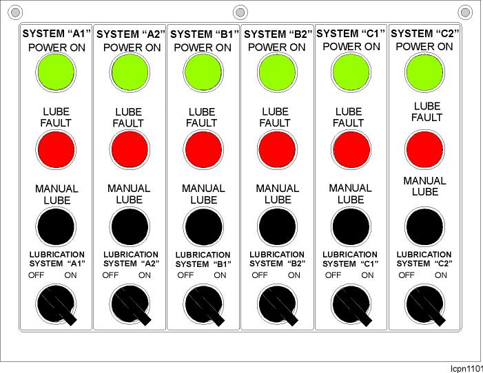
LOWER WORKS LUBRICATION
Although this machine does not spend very much time being propelled between digging sites, there are considerable forces exerted on the lower works of the machine. The severe loads and oscillations created during the constant cycles of the digging process tend to squeeze the lubricant out of bushings, creating a circumstance for wear if proper lubrication habits are neglected.
With the high possibility of operation while submersed in water the applied lubricant should have properties which allow for protection under theses circumstances.
When propelling over any long distances the machine should be lubricated at least every 1500 feet of travel, or every ½ hour. Bearings and bushings should be carefully watched and force lubricated until they run cool if evidence of heat buildup is apparent.
Under extremely harsh conditions such as propelling up a hill, frequent turns, or through deep water and mud the lubrication frequency should be increased.
PROPEL MACHINERY LUBRICATION
Propel planetary gearcases should be checked every 48 hours. Inspect the lubricant level with the machine on level ground and add the required amount of the recommended lubricant if necessary. If water has accumulated within the gearcases, remove the drain plug and drain into a container for waste removal, then refill with clean lubricant.
When radical changes in temperature, or at the recommendation of a testing facility, make it necessary to change the lubricant within a gearcase, it is advised to drain the box immediately after propelling the machine. This will allow for a more thorough removal of contaminants and foreign material due to the elevated temperature and suspension of particles within the lubricant.
LUBRICANT REPLACEMENT/SAMPLING
The recommended mineral oils should have additives that imporve corrosion protection and aging resistance, as well as reduce wear in the mixed friction field. Polyalphaolefin oils (oils on the basis of synthetic hydrocarbons) as well as bio-oils (oils on the basis of synthetic ester) which satisfy the demands specified for industrial type gear oils according to DIN 51517, part 3, are also permitted. Designation to DIN 5157 part 3 :...................CLP 220 ISO viscosity to DIN 51519 :.........................ISO - VG 220 Kinematic viscosity at 40° C :.......................min. 199 mm2/s (cSt) max. 242 mm2/s (cSt) FZG test A /8,3/90 to DIN 51354, pg. 2 :........min. breakdown load stage 12
The lubricant is to be selected from a proven, stable, and reliable lubricant vendor that meets the above listed specification.
It is strongly suggested that the gearcase lubricant be part of a routine spectrometric oil analysis program to forecast impending problems and thereby reduce the possibility of catastrophic failure. This analysis should take place every 250 propel hours and monitor the elements listed in the following table, at a minimum:
Element Normal Excessive Critical
Iron <400 400-700 >700 Copper <25 25-60 >60 Chromium <5 5-15 >15 Silicon <40 40-60 >60
NOTES: 1.All values are Parts per Million. 2.Partical count may be higher during the initial run-in period. 3.The oil should be changed when any element value exceeds normal levels. 4.Maintain an analysis record using the gearcase serial number and machine operating hours.
LUBRICANT CHANGE CYCLE
For all machinery motions - Hoist, Crowd, Swing & Propel - the gearcase lubricant should be first changed after approx. 500 machine operating hours.
The lubricant should then be changed every 6,000 hours or 12 months thereafter, whichever comes first. Flush the gearcase prior to refilling with new oil.
To fill the propel gearcase, remove the inboard plug at the center of the gearcase. Remove the oil breather at the top of the gearcase and fill the gearcase with oil until oil flows from the unplugged port. Replace the removed plug. Oil capacity is approx. 70 US Gallons (265 liters)
REVOLVING FRAME LUBRICATION
Always keep the swing rack and roller path coated liberally with the proper lubricant and check daily. In the event of severe accumulations, remove accumulated material and re-lubricate the area before placing the machine back into service.
Although the machinery contained within the house is not exposed to the extreme conditions of some other machine components, the loading and stresses exerted on this equipment are severe. Longevity of these components is largely dependent upon proper lubrication.
Spray valves are mounted at the same height on both sides of the pinion. The spray valves receive air from the brake lines and lube from system B1.
HOIST MACHINERY LUBRICATION
The hoist machinery drive is comprised of 2 stages of gear reduction. The first stage gear reduction is an enclosed system running submersed in lubricant. The gearcase housing is equipped with lubricant level check plugs on the right side of the case. A filter breather is provided to allow for air entry to equalize pressure differentials created by the warming and cooling of the gearcase, allows moisture to escape and prevents contaminants from entering.
The second stage of gear reduction is operating as a semi-enclosed system lubricated by OGL. The drum shaft bearings are grease lubricated by System “C-1” along with the intermediate shaft of the hoist gearing. The motor pinion shaft bearings are splash lubricated from the 1st stage gearcase.
HOIST OIL COOLER
The Hoist Gearcase temperature is maintained by recirculating lubricating oil through a gearcase oil cooler.
The Gearcase Cooler is located beneath the revolving frame, on the left side of the machine, just behind the hoist machinery. It is supported by a set of beams bolted to the bottom of the revolving frame. Should the cooler assembly require removal or replacement:

1. Drain any fluid from the cooler, oil pump and lines between the cooler and the hoist gearcase.
2. Shut off the valves and disconnect the fluid lines at the oil pump and at the oil filter.
3. Support the cooler and support beam assembly with a jack(s) beneath the base of the cooler.
DANGER: DO NOT PROCEED UNTIL THE COOLER AND SUPPORT ASSEMBLY IS FULLY SUPPORTED. The weight of the cooler assembly and support beams is approx. 800 Lbs.
4. With the supports and the cooler fully supported, remove the .75 inch capscrews (16 places) that fasten the 4 vertical posts of the supports to the revolving frame.
5. Carefully lower the cooler and support assembly down and out from beneath the revolving frame.
The cooler, cooler motor and/or oil pump can now be repaired or replaced.
The cooler pump and pump gearcase can be serviced without removal of the cooler or support structure. The filter assembly is in the output line at the rear of the cooler assembly. The filter cartridge can be replaced by removing the screws and cover at the top of the filter canister.
FILTER ELEMENT CLEANING
The oil filter for the hoist planetary gearcase oil cooler has a removable, wire mesh filter element that can be cleaned and reused several times. Use the following method:
1. Clean any coarse dirt from the pressure side of the element with normal cleaning solvents and a smooth bristled brush (not a wire brush). This process can be done under a jet-stream, not a bath, to help prevent the removed particles from reaching the clean side of the element.
2. After cleaning, use compressed air to blow through the element from the clean side. Filter elements which are filtered
from inside to outside must use a dirt pan as shown in the figure.
3. Next dip the cleaned element in cleaning fluid to pick up any remaining dirt particles. Use compressed air to blow out the element as in step 2 above.
4. Repeat the above steps until all dirt particles have been removed from the filter element.
NOTES:
• Handle the mesh of the element carefully to avoid damage through improper handling.
• The filter element cannot be 100% cleaned. Therefore, the element should be cleaned a maximum of 3 times then discarded.
• Filter seals should be inspected and replaced as required during filter cleaning and maintenance.
OIL PUMP
The heart of the power unit is the hydraulic pump. It is self-lubricating. Preventive maintenance is limited to keeping the system fluid clean This is done by changing the filters frequently. The recommendations listed below are a minimum requirement.
All return line filters and pressure filters should be changed a minimum of two times per year or, upon the visual or electrical indicator signaling otherwise.
The suction strainer (immersed below the oil level in the reservoir) should be cleaned once a year or every 4000 operating hours. The suction strainer should be removed from the reservoir and can be cleaned with compressed air, blowing from the inside out. If there are holes in the mesh or if there is mechanical damage, the strainer should be replaced. It is especially important that the suction or inlet piping and fittings be tight and in good condition to prevent air from being drawn into the pump.
The reservoir air breather should be changed or cleaned once a year or every 4000 hours. The air breather filters all air drawn into the reservoir. Failure to change or clean this filter can result in
pump failure.
The electric motor requires very little attention when kept clean and dry.
CROWD MACHINERY LUBRICATION
The crowd machinery includes 2 gearcases. The crowd first and second stages of gear reduction are totally enclosed systems submerged in gear lubricant. The gearcase is provided with an oil level plug to check for adequate lubrication, and a filter breather. The third stage of gear reduction, the crowd drum gear, is lubricated by OGL from lube system “B-1”. The bearings of the crowd drum, along with the shafts of the crowd reduction system are lubricated by grease from lube system “C-1”
SWING MACHINERY LUBRICATION
The swing machinery is primarily composed of an enclosed planetary gearcase on either side of the machine’s swing rack. The gearcases are self contained units with their own individual pump, filtering system and lubricant reservoir. Lubricant levels should be checked at least every 48 hours with a visual inspection for leakage at the start of each shift.
Swing Machinery Components
A filter breather is provided on each planetary gearcase to allow for air entry to equalize pressure differentials created by the warming and cooling of the gearcase, to allow moisture to escape and to prevent contaminants from entering.
The swing pinions and lower swing shaft bearings are lubricated with open gear lubricant from System “B-1”.
AIR COMPRESSOR LUBRICATION
The air compressor supplied with the machine has very specific lubrication needs. For the details of servicing this equipment you should refer to the manufacturer’s instructions and the specific lubricant recommendations made later within this section.
CROWD ROPE TAKE-UP MECHANISM LUBRICATION
When repairing and reassembling the take-up mechanism, fully coat all contact surfaces with Molykote before assembly. This includes the screw rod, take-up guide, worm gear housing, worm gear wheel, worm shaft, shaft bushings and shaft thrustwashers. Refer to CROWD ROPE TAKE-UP MECHANISM in Section 5 - SERVICE PROCEDURES in this manual for the proper assembly procedures.
With the mechanism fully assembled, pump grease into the worm shaft housing at the base of the worm shaft. Approximately 1.5 gallons of grease are required.
FRONT END LUBRICATION
The front end equipment is exposed to the most extreme working environment of any part of the machine. The proper amount of lubrication and its quality is imperative to achieving a substantial service life from these components. Daily inspection and monitoring of the lubrication system will result in both parts durability and the reduction of machine downtime.
Boom Foot Pins: Although not under constant movement during the operation of the machine, the boom point feet are subjected to high loads and oscillations in a variety of directions. Virtually all movement of the front end equipment will exert a load on the pins. OGL is introduced from lube system “A-1” to reduce wear.
Saddle Block: The saddle block bears the brunt of movement from the dipper, dipper handle, attached equipment and any material being moved. The saddle block lube points need to be checked at least before each shift to avoid dry spots and accumulations of foreign material. The saddle block lube to the handle is received from lube system B-2. The crowd sheaves and shipper shaft bushings lube is received from lube system A-1.
Sheaves: Both fixed and rotating front end sheaves are subjected to loads introduced by the ropes as they move the larger components of the machine. The sheave bearings on the boom point, the crowd sheaves and the connection points of the structural strands are lubricated by lube system “A-1”.
Wire Ropes: Running and structural wire ropes have very specific requirements for lubrication in order to survive the difficult conditions they are forced to operate within. Without proper lubrication and maintenance the expected life from costly wire ropes will be seriously degraded. Refer to Section 9 ENGINEERING DATAl for general care and maintenance of wire ropes.
Suspension Ropes: The suspension ropes support the boom as well as the rest of the front end equipment. These ropes are under constant tension but also sustain additional loads during machine operation. Lubricate the suspension rope sockets approx. every 3 months or 1250 hours of machine operation.
LINCOLN TYPE SL-1 LUBRICANT INJECTORS
These pressure-operating, spring-reset, series-installed injectors are supplied in banks mounted on manifolds or individually. Each injector expels a maximum of .08 cu. inch of lubricant from its outlet port each cycle. Dual outlet ports on each injector permit the injectors to be piped in series for increased lube supply to a common point. The quantity of lube to each point on this machine has been carefully designed by our engineers for proper coverage. Each injector output can be adjusted; however Bucyrus recommends that injectors initially be set and used at their maximum setting.
NOTE: MAXIMUM Operating Pressure: 3,500 PSI RECOMMENDED Operating Pressure: 2,500 PSI MINIMUM Operating Pressure: 1,850 PSI MAXIMUM Recharge Pressure: 600 PSI
CAUTION: STORED ENERGY! Contact with or ingestion of petroleum products can be harmful. Automatic lubrication systems operate under pressure. Before opening any lube supply line, relieve the system and that line in particular, of any residual pressure.
To set an injector for maximum output:
1. Loosen locknut. 2. Turn adjusting nut until there is a small gap at the top of the stem. 3. Orient the adjusting nut so that the opening is toward the front of the injector. 4. Tighten the locknut. To reduce an injector’s output: 1. Loosen locknut. 2. Turn adjusting nut clockwise (CW) until desired discharge rate is obtained. This forces the stem into the body, retarding the stem’s movement. 3. Set the locknut.
CAUTION:Do not turn adjusting nut down (clockwise) more than 5 full turns from the maximum discharge setting. Check output flow from injector at this time to ensure it is still operating. If not, back off adjusting nut until injector does consistently operate. Inspect the adjusted injector for operation over 3 or 4 cycles after returning machine to work to make sure it is functioning.
LUBRICANT INJECTOR OPERATION
STAGE 1: The injector piston is in its normal or reset position. The discharge chamber is filled with lubricant from the previous cycle. Under the pressure of incoming lubricant, the slide valve is about to open the passage leading to the piston.
STAGE 2: When the slide valve uncovers the passage, lubricant is admitted to the top of the piston, forcing the piston down. The piston forces lubricant from the discharge chamber through the outlet port to the bearing.
STAGE 3: As the piston completes its stroke, it pushes the slide valve past the passage, cutting off further admission of lubricant to the passage. The piston and slide valve remain in this position until lubricant pressure in the supply line is vented (relieved) at the pump.
STAGE 4: After the pressure is relieved, the compressed spring moves the slide valve to the closed position. This opens the port from the measuring chamber and permits the lubricant to be transferred from the top of the piston to the discharge chamber.
NOTE: The injectors may be mounted individually, or grouped in a manifold at one location.
INJECTOR ADVANTAGES
LUBRICATION BENCHMARKS
ACSL - AIR COMPRESSOR (SCREW-TYPE) LUBRICANT
SCOPE: Lubrication performance requirements and recommendations for Air Compressor (Screw-type) Lubricants.
IMPORTANT NOTE
These lubricant performance requirements for screw-type air compressors are only good for Sullair screw compressors. If the machine is equipped with air compressors manufactured by other than Sullair you must refer to the vendor’s maintenance information provided with the machine and Section 7 of this manual.
LUBRICANT RECOMMENDATIONS:
The following are listed service requirements (including lubrication) of the Sullair Air Compressor:
Ambient Fluid & Filter Change Separator Change Air Filter Change Temperature Lubrication Period (Hrs.) Period (Hrs.) Period (Hrs.) ---------------------- --------------------------------------------------------------------------------------------------- ---------------------- -10ºF to +90ºF Sullube 8000 Hrs. 8000 Hrs. 4000 Hrs. (-23ºC to +32ºC) Sullair LLL-4-32 8000 Hrs. 8000 Hrs. 4000 Hrs. SRF 1/4000 4000 Hrs. 4000 Hrs. 4000 Hrs.
NOTE: For additional information, refer to the Vendor supplied manual provided. For additional questions, please contact either the Vendor or Bucyrus Service.
NOTE: For light-duty, high-humidity service where condensed moisture and emulsification may occur, the fluid change interval should be reduced to 300 Hrs. maximum. A nondetergent fluid with rust, oxidation and foam inhibitors, and good water sepearation characteristics should be used.
NOTE: These performance requirements are bench marks and not a specification. Therefore, meeting these limits as described above does not relieve the supplier of the responsibility associated with brand name products.
MPO - MULTIPURPOSE OIL
SCOPE: Lubricant performance requirements for Multi-Purpose Oil.
APPLICATION: The addition of a lubricant to the compressed air system (not for screw-type air compressor systems - see ACSL), hand oil cans, etc.
GENERAL REQUIREMENTS:
1. Must be fluid at temperature applied. 2. Should contain rust inhibitor.
3. Motor oil - API service classification “MS”.
VISCOSITY RECOMMENDATIONS:
1. Air Line Lubricant
AMBIENT TEMPERATURE SAE NUMBER Below 10°F 5W Above 10°F 10W
2. Hand Oil Can - Viscosity suitable for application and temperature.
NOTE: These performance requirements are bench marks and not a specification. Therefore, meeting these limits as described above does not relieve the supplier of the responsibility associated with brand name products.
RWRL - RUNNING WIRE ROPE LUBRICANT
SCOPE: Lubrication performance requirements for hoist rope lubricant.
APPLICATION: Primarily for hoist ropes or any other running ropes where fatigue and not wear is of prime concern.
GENERAL REQUIREMENTS:
1. Penetrate between adjacent wires in order to lubricate and protect them against wear and to keep the rope core from drying out and deteriorating. 2. Provide a lubricant between sheaves and wire rope. 3. Resist being washed off. 4. Protect against rusting or corrosion. 5. Form a non-sticky film so that dust and dirt will not build up on the wires. 6. Remain pliable and resist stripping at the lowest temperatures to which the rope will be exposed. 7. Preferably, it should form a light colored transparent film so that wear, corrosion or broken wires can be readily detected by inspection. 8. Be capable of easy application, both manually and by devices without being heated.
COMPOUNDING:
Suitable for penetrating between the adjacent wires of a rope in order to lubricate them and also to replenish the lubricant in the core.
SPECIAL REQUIREMENTS:
1. Must pass United States Steel Retention Test Using a Timken Tester
2. Shell Four Ball E.P. - (ASTM D-2596)
Load wear index, kg., min.: 40 Load weld kg., min.: 250
3. Shell Four Ball Wear - (ASTM D-2266)
Wear scar diameter, mm., max.: 0.60
4. Timken O.K. Load lbs., min. - (ASTM D-2782): 45
5. Copper Strip Corrosion - (ASTM D-130): pass
6. Suggested Application Temperature Ranges
There should be a lubricant for each of the following temperature ranges: 110°F to 30°F 40°F to 9°F 10°F to -50°F
NOTE: These performance requirements are bench marks and not a specification. Therefore, meeting these limits as described above does not relieve the supplier of the responsibility associated with brand name products.
SCHEMATICS - AUTOMATIC LUBRICATION
The following pages contain a series of block diagrams depicting the schematic layout of the automatic lubrication systems.
Systems “A” and “B” automatically disperse Open Gear Lubricant (OGL) to critical portions of the machine.
System “C” is a grease system that lubricates items requiring a lubricant of slightly different characteristics.
SPECIFICATION FOR MPG – MULTI-PURPOSE GREASE
SD4711 (August 18, 2005)
SCOPE:
2. Materials furnished under this specification are primarily intended to lubricate heavy duty ball, roller, and plain bearings.
3. The material furnished under this specification must be dispensable through the distribution lines of a centralized lubrication system to the most remote application point, at the lowest anticipated operating temperature. It must not plate or plug components of the centralized lubrication system such as injectors or metering blocks.
4. The particular grade or consistency selected must perform within the specific temperature range in which it is utilized.
PHYSICAL CHARACTERISTICS:
1. Heat Resistance - Shall be thermally stable, should not flow or harden in service.
2. Retention - Shall not exhibit high leakage.
3. Stability - Shall work continuously with a minimum change in consistency.
4. Water Resistance - Shall withstand water washout or leaching.
5. Reversibility - Shall be stable with repeated heating and cooling.
6. Pressure Separation - Shall resist oil-soap separation.
7. Extreme Pressure - Shall withstand heavy shock loading.
8. Compatibility –
a. Low temperature greases shall be compatible with mineral oil base greases. b. Grease must be compatible with oil seal lip materials (Nitriles, Viton), and all centralized lubrication system components (i.e. gaskets, o-rings, vent valves, etc.). Reference ASTM D 4289-03.
9. Compounding –
a. Suitable for producing the extreme pressure characteristics (without inert fillers) required for heavy duty ball, roller, and plain bearing lubrication.
SPECIFICATION FOR MPG – MULTI-PURPOSE GREASE
SD4711 (August 18, 2005)
b. Base fluid is to be mineral or synthetics which are compatible with mineral base. c. Thickener types are to be of the following varieties: Aluminum, Lithium, or
Calcium.
SPECIFICATION FOR MPG – MULTI-PURPOSE GREASE
SD4711 (August 18, 2005)
Ambient Temperature
-1°C to +43°C -18°C to +27°C Less than -12°C (See Note #1) (+30°F to +110°F) (0°F to +80°F) (Less than +10°F) NLGI Consistency # ASTM D-217 2 1 1, 0, 00 (See Note #2) Dropping Point °C(°F) ASTM D-2265 177(350) 177(350) 177(350) Minimum Timken O.K. load-lbs(kgf) ASTM D-2509 50(23) 50(23) 50(23) Minimum Shell Four Ball EP Load wear index (LWI) kg ASTM D-2596 65 65 65 Minimum Load Weld kg ASTM D-2596 400 400 400 Minimum Shell Four Ball Wear Wear Scar mm Maximum ASTM D-2266 0.6 0.6 0.6 40KG for 1 hour @ 75°C @ 1200 RPM Copper Strip Corrosion ASTM D-4048 2e 2e 2e 24 Hrs @ 100°C (212°F) Rust Test ASTM D-1743 Pass Pass Pass Viscosity of Base Fluid ASTM D-445 460cSt @ 40°C 220cSt @ 40°C 130cSt @ 40°C Minimum Motormatic Grease Worker Mechanical Stability ASTM D-217A 10% 10% 10% 10,000 strokes, Maximum change Roll Stability Test Maximum change ASTM D-1831 15% 15% 15% in 2 hours Wheel Bearing Test 6 hours @ 104°C(220°F) ASTM D-1263 10% 10% 10% Maximum loss (NLGI #1 Only) Water Washout Test Loss @ 38°C(100°F), ASTM D-1264 5% 5% 5% Maximum (NLGI #1 Only)
SPECIFICATION FOR MPG – MULTI-PURPOSE GREASE
SD4711 (August 18, 2005)
PROPERTY REFERENCE
Lubricating Solids (Molybdenum Disulfide, Graphite, Etc.) % by Weight Lubricating Solids (Molybdenum Disulfide, Graphite, Etc.) Particle Size, (Microns, max.)
REQUIREMENT
U.S. Steel test method - Cake penetration not less than 25% of grease penetration. U.S. Steel method - not less than 0.10 grams flow per second at the lowest anticipated ambient temperature. (Testing temperature not less than -34°C/-30°F). To vent from 1800 psi (127 kgf/cm^2) to less than or equal to 600 psi (42 kgf/cm^2) within 30 seconds at the lowest anticipated ambient temperature (Testing temperature not less than -25°C/-13°F).
Less than or equal to 5%
10 Microns
NOTES:
1. Ambient Temperature - The ambient temperature shall be the temperature at the point of lubricant application.
2. Low Temperature Grease - For extended use in low temperature (-12°C to -46°C / +10°F to -50°F) areas, this product should be capable of slumping in containers and should be pumpable through lube lines without the aid of heat tracing.
This product should meet the Mobility and Pump-ability criteria for the lowest anticipated ambient temperature. In order to minimize compatibility problems, it is desirable that the thickener and additive system be compatible with the additional grades that are suitable for the other ambient temperatures.
SPECIFICATION FOR MPG – MULTI-PURPOSE GREASE
SD4711 (August 18, 2005)
CERTIFIED LUBRICANTS:
Lubricants certified by their manufacturers as complying with this specification will be listed on the “Certified Lubricants Listing for Multi-Purpose Grease” (see the Bucyrus International, Inc. web site www.bucyrus.com for the latest listing). The use of non-certified lubricants may invalidate the Bucyrus International, Inc. product warranty obligation.
Specific product selection is the responsibility of the equipment operator/owner and is dependent on climate, application, performance and regional/local regulatory requirements.
Lubricant manufacturers seeking to certify their products should contact the following for direction:
SPECIFICATION REVISIONS:
This specification is subject to change without notice. Please contact the following for the latest specification:
SPECIFICATION FOR OGL – OPEN GEAR LUBRICANT
SD4713 (August 18, 2005)
SCOPE:
2. Materials furnished under this specification are primarily intended to lubricate open gears, but may also be used to lubricate racks, bushings, rails, rollers, dipper handles and propel mechanism components.
3. The material furnished under this specification must be dispensable through the distribution lines of a centralized lubrication system to the most remote application point, at the lowest anticipated operating temperature. It must not plate or plug components of the centralized lubrication system such as injectors, metering blocks, or spray nozzles.
4. This specification covers open gear lubricants that may be applied in service at temperatures ranging from -50°C (-58°F) to the highest ambient temperature conditions. The particular grade or consistency selected must perform within the specific temperature range in which it is utilized.
PHYSICAL CHARACTERISTICS:
1. Materials furnished under this specification may be asphaltic (bitumen) compounds, or blends of a thickener and mineral oils and/or synthetic fluids. They may be in the form of viscous fluids, semi-fluid greases or pastes.
2. Materials furnished under this specification are produced with highly fortified blends of viscous fluids combined with additives to form stable, long lasting, high load carrying, wear resistant films that lubricate under mixed film and boundary conditions.
3. Open gear lubricants supplied under this specification must have excellent adhesive and cohesive qualities, must not chip or throw off, and must provide sufficient film thickness and scuffing resistance to prevent metal to metal contact between applications under all operating conditions.
4. Various grades or consistencies of open gear lubricants may be required to provide proper lubrication and application properties over a wide range of ambient temperatures. The consistency of the lubricant as applied must be appropriate for the method of application, and the in-service consistency shall be appropriate for the lubricant to meet or exceed the minimum performance requirements listed in the "MINIMUM PERFORMANCE REQUIREMENTS" section.
SPECIFICATION FOR OGL – OPEN GEAR LUBRICANT
SD4713 (August 18, 2005)
5. Viscosity, a fluid's resistance to flow, is the principal physical characteristic of a fluid in terms of its ability to produce a lubricating film between two interfacing surfaces.
All lubricating fluids possess a natural viscosity that may be altered (enhanced) by additives such as resins or polymers. Some "viscosity enhancers" are shear sensitive, which could result in insufficient protection of the lubricated components under high load, elevated temperatures and/or high shear conditions. The viscosity of the fluids utilized in the open gear lubricants shall be sufficient under operating conditions for the product to meet or exceed the performance requirements listed in the "MINIMUM PERFORMANCE REQUIREMENTS" section.
6. Open gear lubricants supplied under this specification must be specifically formulated to protect surfaces, reduce wear, and provide satisfactory service life under all anticipated operating conditions.
7. Open gear lubricants supplied under this specification must have excellent water tolerance and rust preventive qualities, as well as minimal dripping qualities for operation over wide temperature ranges.
8. Should the material furnished under this specification contain a diluent to improve dispensability, special care must be exercised to ensure its compatibility with all centralized lubrication system components, i.e., gaskets, o-rings, vent valves, etc., and oil seal lip materials (Nitriles, Viton). Reference ASTM D 4289-03.
9. For extended use in low temperature areas, open gear lubricants supplied under this specification should be capable of slumping in containers and should be pumpable through lube lines without the aid of heat tracing. In order to minimize compatibility problems, it is desirable that the thickener and additive system be compatible with the additional grades that are suitable for the other ambient temperatures.
SPECIFICATION FOR OGL – OPEN GEAR LUBRICANT
SD4713 (August 18, 2005)
MINIMUM PERFORMANCE REQUIREMENTS:
PROPERTY REFERENCE REQUIREMENT
Flash point of product as applied, minimum (base product with diluent)
Ambient Temperature (See Note #1) -50°C(-58°F) to +10°C(50°F) ASTM D92 / ISO 2592
61°C (142°F)
Above +10°C(50°F) 80°C (176°F) Flash point of base fluid(s), minimum ASTM D92 / ISO 2592 140°C (284°F) Rust protection ASTM D 1743 Pass Copper strip corrosion maximum rating ASTM D 4048 2e 24hr. @ 100°C (212°F) Four ball EP test weld point, minimum kgf ASTM D 2596 800 (base product without diluent) Load wear index (LWI), minimum ASTM D 2596 120 (base product without diluent) Four ball wear test 60 minutes @ 40 kgf. ASTM D 2266 0.7 Maximum scar, mm (base product without diluent) Adhesive properties Must adhere to surfaces at the lowest anticipated ambient temperature. Pumpability, Lincoln Ventmeter To vent from 1800 psi (127 kgf/cm^2) to less than or equal to 600 psi (42 kgf/cm^2) within 30 seconds at the lowest anticipated ambient temperature (Testing temperature not less than -25°C/-13°F).
Minimum Base Fluid Viscosity Ambient Temperature (See Note #1) °C (°F) -50 to +10 (-58 to +50) -20 to +40 (-4 to +104) +10 to +50 (+50 to +122) ASTM D 445
680 cSt at 40°C 1860 cSt at 40°C 3600 cSt at 40°C
Lubricating Solids (Molybdenum Disulfide, Graphite, Etc.) Particle Size, (Microns, max.) 15 Microns
NOTE: 1. Ambient Temperature - The ambient temperature shall be the temperature at the point of lubricant application.
SPECIFICATION FOR OGL – OPEN GEAR LUBRICANT
SD4713 (August 18, 2005)
CERTIFIED LUBRICANTS:
Lubricants certified by their manufacturers as complying with this specification will be listed on the “Certified Lubricants Listing for Open Gear Lubricant” (see the Bucyrus International, Inc. web site www.bucyrus.com for the latest listing). The use of non-certified lubricants may invalidate the Bucyrus International, Inc. product warranty obligation.
Lubricant manufacturers seeking to certify their products should contact the following for direction:
SPECIFICATION REVISIONS:
This specification is subject to change without notice. Please contact the following for the latest specification:
SPECIFICATION FOR ENCLOSED GEARCASE LUBRICANT
(September 1, 2005)
SCOPE:
This specification covers the requirements for “Enclosed Gearcase Lubricant” used on models 495BII, 495HF, 495HR and 495HD Electric Mining Shovels.
The materials furnished under this specification are intended to lubricate spur, helical and spiral bevel gears as well as anti-friction bearings at the interior of enclosed planetary and non-planetary type gearcases (Hoist, Swing, Crowd and Propel).
This specification covers “Enclosed Gearcase Lubricants” that may be applied in service at temperatures ranging from –50ºC (-58ºF) to the highest ambient temperature conditions.
GUIDELINES FOR SELECTING AN APPROVED LUBRICANT:
Step #1
Using Table 1, determine the recommended oil type (Mineral or Synthetic) based upon the anticipated ambient temperature range.
AMBIENT TEMPERATURE RANGE:
Ambient Temperature: The ambient temperature is defined as the air temperature in the immediate vicinity of the gearcase.
a. Use atmospheric temperature for gearcases located outside of the machinery house (Swing, Crowd and Propel Gearcases).
b. Use machinery house temperature for gearcases located inside of the machinery house (Hoist Gearcase) for some machines are equipped with machinery house heaters.
c. If the ambient starting temperature approaches the lubricant pour point, external heaters may be required to facilitate starting and insure proper lubrication. Use oil temperature for gearcases having oil immersion heaters.
Page 1 of 4
SPECIFICATION FOR ENCLOSED GEARCASE LUBRICANT
(September 1, 2005)
Table 1
Ambient Temperature Range ISO Viscosity Grade / Oil Type
14 F to 100 F (-10 C to 37 C) ISO VG 320 / Mineral or Synthetic (poly- -olefin) Oil
Less than 14 F to 120 F (Less than -10 C to 50 C) ISO VG 320 / Synthetic (poly- -olefin) Oil Under normal circumstances, an ISO VG 320 oil viscosity is required for all Gearcases (Hoist, Swing, Crowd and Propel). For cold weather applications, an ISO VG 220 oil viscosity may be used for the Propel Gearcases to help ensure that the lubricant pour point remains below that of the ambient starting temperature. The pour point and flash point of individual brand name gear oils must be observed. Refer to the oil manufacturers technical data sheets for these properties. Step #2 Select an approved lubricant for the Hoist, Swing, Crowd and Propel Gearcases from the Approved Lubricant Tables 2 & 3.
APPROVED LUBRICANTS:
Lubricants that have been approved for use by the Gearcase manufacturers are listed in the Approved Lubricant Tables 2 & 3. The use of non-approved lubricants may invalidate the Bucyrus International, Inc. product warranty obligation.
Page 2 of 4
SPECIFICATION FOR ENCLOSED GEARCASE LUBRICANT
(September 1, 2005)
Manufacturer Product Description
BEL-RAY Bel-Ray 100 Gear Oil 90 BP Energol GR-XF 320
CASTROL
CHEVRON Alpha SP 320 Alpha MAX 320 Optigear BM 320 Tribol 1100/320 Chevron Ultra Gear Lube 320 Gear Compound EP 320
ESSO
FUCHS
Spartan EP 320 (Only Product Originating from Europe) Renolin CLP 320 Plus LE (Lubrication Engineers) Almasol 605 MOBIL Mobilgear XMP 320 PETRO CANADA Ultima EP 320 SHELL Omala F 320 Auriga EP 320 TEXACO Meropa 320 Meropa WM 320 WHITMORE Paragon 320
Planetary type Crowd Gearcase.
Page 3 of 4
SPECIFICATION FOR ENCLOSED GEARCASE LUBRICANT
(September 1, 2005)
Manufacturer Product Description
BEL-RAY Synth. Gear Oil 6692 BP Enersyn EP-XF 320 Enersyn HTX 320 Optigear Synth. A 320 Optigear Synth. X 320 CASTROL Alphasyn EP 320 Alphasyn T 320 Tribol 1510/320 Tribol 1710/320 CHEVRON Tegra Synth. Gear Lube 320 FUCHS Renolin Unisyn CLP 320 MOBIL
PETRO CANADA
Mobil SHC 632 Mobilgear SHC XMP 320 Ultima Synth. EP 320 Traxon E Synth. 80W-140 SHELL Omala HD 320 TEXACO Pinnacle EP 320 WHITMORE Decathlon F 320
Planetary type Crowd Gearcase.
SPECIFICATION REVISIONS:
Page 4 of 4
CERTIFIED LUBRICANTS LISTING
(November 8, 2005)
SCOPE:
Materials furnished under the specifications for “OGL–Open Gear Lubricant (SD4713)” and “MPG-Multi Purpose Grease (SD4711)” are intended for use on Bucyrus International, Inc. mining machinery (Electric Mining Shovels, Draglines and Rotary Blasthole Drills).
Lubricants certified by their manufacturers as complying with the Bucyrus International, Inc. specifications for “OGL–Open Gear Lubricant (SD4713)” and “MPG-Multi Purpose Grease (SD4711)” are listed in the tables below.
LUBRICANT SELECTION:
Specific product selection is the responsibility of the equipment operator/owner and is dependent on climate, application, performance and regional/local regulatory requirements.
Each lubricant listed in the tables below has a unique operating temperature range. It is the responsibility of the lubricant manufacturer to recommend the appropriate products based upon the anticipated ambient temperature range for each application.
CERTIFIED LUBRICANT LISTING FOR “OGL–OPEN GEAR LUBRICANT (SD4713)”
Manufacturer Product Description
Bel Ray Bel Ray Bel Ray Bel Ray Bel Ray Bel Ray Bel Ray Molylube SF 100 Sub-Arctic 77070 Molylube SF 100 Arctic 77020 Molylube SF 100 Light 76990 Molylube SF 100 Medium 77010 Molylube SF 100 Heavy 77000 Molylube Unee NS 70550 Molylube Unee 70600
Bel Ray Bel Ray Bel Ray Molylube Unee 70540 Molylube SD-1 70620 Molylube Gear TAC Light 68990
Bel Ray
Molylube Gear TAC Regular 68940 Bel Ray Molylube Gear TAC Medium 68950 Chemtool Inc. Alpha OGL-680 Chemtool Inc. Alpha OGL-1860 Chemtool Inc. Alpha OGL-3600 Haycock Petroleum Shovel Lube OGL 1.5 Ultra Imperial Oil Dynagear Heavy Schaeffer Mfg. Silver Streak Quickvent All Season (#196ALL) Schaeffer Mfg. Silver Streak Quickvent Arctic (#196ARC) Schaeffer Mfg. Silver Streak BGL 100 Schaeffer Mfg. Silver Streak BGL 200 Schaeffer Mfg. Silver Streak BGL 300
CERTIFIED LUBRICANTS LISTING
(November 8, 2005)
Shell Malleus Grease GL 3500
Shell
Malleus OGM Heavy Shell Malleus OGM Extra Heavy Whitmore Mfg. Co. Axiom Multiservice Mining Lubricant - Arctic Whitmore Mfg. Co. Axiom Multiservice Mining Lubricant - Medium Whitmore Mfg. Co. Axiom Multiservice Mining Lubricant - Heavy
CERTIFIED LUBRICANT LISTING FOR “MPG-MULTI-PURPOSE GREASE (SD4711)”
Manufacturer Product Description
Bel Ray Bel Ray Bel Ray Bel Ray Bel Ray Bel Ray Bel Ray Bel Ray Bel Ray Bel Ray Bel Ray Bel Ray Molylube AC 1000 40890 Molylube AC 1000 40900 Molylube AC 1000 40922 Molylube LC135 67800 Molylube LC135 67810 Molylube LC135 67820 Molylube LC135 67832 Molylube LC133 67840 Molylube LC133 67850 Molylube LC133 67860 Molylube LC133 67872 Molylube LC131 27660
Bel Ray Bel Ray Bel Ray Bel Ray Bel Ray Bel Ray Bel Ray
Molylube LC131 27670 Molylube LC131 27680 Molylube LC131 27692 Molylube 126 EP 23200 Molylube 126 EP 23220 Molylube 126 EP 23242 Termalene EP 72400 Bel Ray Termalene EP 72420 Chemtool Inc. CSC 174 MGD Chemtool Inc. CSC MP1-220 Chemtool Inc. CSC MP1 Chemtool Inc. CSC MP0 Chemtool Inc. CSC MP00 Haycock Petroleum Calcuplex M5 NLGI #1 Haycock Petroleum Calcuplex M5 NLGI #2 Lubrication Engineers Almagard Vari-Purpose 3750 Lubrication Engineers Almagard Vari-Purpose 3751 Lubrication Engineers Almaplex Ultra-Synthetic 1299 Petro-Canada Supreme EP1 Petro-Canada Supreme EP2 Petro-Canada Precision Moly EP1 Petro-Canada Precision Moly EP2 Petro-Canada Supreme Moly EP0 Schaeffer Mfg. Moly Ultra 800 EP #1 (#221)
CERTIFIED LUBRICANTS LISTING
(November 8, 2005)
Schaeffer Mfg. Moly Ultra Red EP #1 (#229) Schaeffer Mfg. Moly Supreme #1 (#238) Schaeffer Mfg. Moly EP Synthetic Blend #1 (#274) Shell Albida Grease HDX2 Shell Albida Grease MDX 1 Shell Albida Grease MDX 2 Shell Alvania Grease SDX2 Shell Albida SLC 460 Shell Limona LX1 Shell Limona LX2 Shell Albida HLS00 Shell Albida HLS2 Whitmore Mfg. Co. Omnilith 500 Extreme Pressure Grease EP 0 Whitmore Mfg. Co. Omnilith 500 Extreme Pressure Grease EP 1 Whitmore Mfg. Co. Omnilith 500 Extreme Pressure Grease EP 2 Whitmore Mfg. Co. Omnilith 500 M Extreme Pressure Grease EP 0 Whitmore Mfg. Co. Omnilith 500 M Extreme Pressure Grease EP 1 Whitmore Mfg. Co. Omnilith 500 M Extreme Pressure Grease EP 2
LUBRICANT CERTIFICATION PROCESS:
Lubricant manufacturers seeking to certify their products should contact the following for direction:
Bucyrus International, Inc. Engineering Services & Technical Support 1100 Milwaukee Avenue South Milwaukee, Wisconsin 53172 Phone (414) 768-4000
REVISIONS:
This listing is subject to change without notice. Please refer to the Bucyrus International, Inc. web site www.bucyrus.com for the latest listing.
Section 4 Preventive Maintenance
Always refer to the safety information in Section 1 of this manual before starting any maintenance procedure on this machine. Table of Contents
INTRODUCTION...........................................................................................................................3 ELEMENTS OF AN EFFECTIVE MAINTENANCE PROGRAM ...............................................5 SCHEDULED PREVENTIVE MAINTENANCE PROGRAM .....................................................5 GENERAL SAFETY CONSIDERATIONS................................................................................6 MAINTENANCE DURING MACHINE OPERATION........................................................................6 MAINTENANCE PRECAUTIONS ..................................................................................................7 PREVENTIVE MAINTENANCE FOR LUBRICATION.....................................................................8 LUBRICANT CLEANLINESS ...................................................................................................9 FREQUENCY OF INSPECTION AND MAINTENANCE...............................................................10 MAINTENANCE SCHEDULES ....................................................................................................10 DAILY CHECK POINTS.........................................................................................................11 WEEKLY CHECK POINTS...................................................................................................15 MONTHLY CHECK POINTS..................................................................................................17 QUARTERLY CHECK POINTS.............................................................................................21 SEMI-ANNUAL CHECK POINTS ...........................................................................................25 ANNUAL CHECK POINTS.....................................................................................................28 MAJOR COMPONENT LOCATIONS..............................................................................31 Machine Nomenclature ...............................................................................................................31 Lower Works and Crawlers .........................................................................................................32 Crawler Assembly ......................................................................................................................33 Crawler Link Assembly ..............................................................................................................34 Propel Machinery........................................................................................................................35 Cable Reel Assembly ................................................................................................................36 Roller Circle Section View ..........................................................................................................37 Roller Circle Assembly ...............................................................................................................38 Collector Rings, Auxiliary ...........................................................................................................39 Collector Rings, High Voltage.....................................................................................................39 Center Pintle Assembly .............................................................................................................40 Deck Plan ..................................................................................................................................41 Revolving Frame Deck Extensions .............................................................................................42
Hoist Machinery .........................................................................................................................43 Swing Machinery ........................................................................................................................44 Crowd Machinery ........................................................................................................................45 Lubrication Reservoirs................................................................................................................46 Operators Cab ...........................................................................................................................47 Boarding Stairway ......................................................................................................................48 Machinery House Walkways and Platforms ................................................................................49 Front End Equipment .................................................................................................................50 Boom Support Ropes .................................................................................................................51 Dipper Assembly........................................................................................................................52
Section 4 Preventive Maintenance
This section of the manual describes those aspects of preventive maintenance on the machine such as inspection, adjustment and routine repetitive tasks. Information related to lubrication techniques, frequency and service points is also partially included. More detailed information on lubrication and service can be found in Sections 3 and 5 of this manual.
At the end of this section are reproducible maintenance schedules that may assist in record keeping and maintenance scheduling.
INTRODUCTION
A Preventive Maintenance Program is a systematic series of operations performed periodically on equipment in order to prevent breakdowns.
Any breakdown WILL reduce productivity and increase overhead expense. Machinery is only new at one point in time. From that moment, the machinery begins to deteriorate through use and aging. A well organized maintenance program will avoid unexpected high-cost breakdowns and will increase component life.
A systematic approach to the program should be followed and detailed records of all findings kept, to detect potential problem areas. Valuable time and effort can be saved if defects are corrected before they lead to a major breakdown. The records should be reviewed often and kept on file for future reference.
Personnel involved in the program should go through an established training program, to know WHAT to check and HOW to rectify any potential problem area. When personnel are able to do routine maintenance and normal repairs efficiently, downtime is reduced and machine productivity increased. Also, to keep the machine in good running condition, the necessary parts, tools and current information should be kept on hand.
Equipment maintenance is a science and its practice an art. This art can be divided into 6 types of operations - they are:
Inspection is probably the most important operation. Careful observation is required of all parts of the equipment. Slight abnormalities may not interfere with the equipment performance BUT those that are a deviation from the normal should be discovered early. When inspecting, notice placement, state of cleanliness, color, etc. of part(s).
Example: discoloration indicates overheating; all guards, bolts in place and good housekeeping. Cleaning and keeping clean is essential for good operation. Periodic cleaning should be more frequent on exposed parts than those which are contained within cabinets.
Parts, connections and joints should be free of dust, corrosion and other foreign matter.
A Feeling operation is used more often to check guarded rotating machinery for vibration due to worn parts, lack of lubrication, overheating, etc. Feeling operation on electrical items should be performed as soon as possible AFTER power has been removed and the circuit grounded. Feeling of excessive heat may indicate an overloaded condition and should be corrected.
A Tightening operation should be done on all connections that have worked loose due to vibration, etc. Loose parts are a definite hazard because they may fall out of place and damage nearby components. The importance of firm mounting and tight connections cannot be overemphasized. Always replace missing or broken bolts with proper size and use the correct tools. Adjusting should be done when inspection indicates that it is required to maintain normal operating conditions. Specific adjustment is contained in the “Mechanical
Adjustment Section” of this manual, the electrical manual or the component manufacturer’s manual.
Lubrication refers primarily to the application of CORRECT LUBRICANT in the
CORRECT AMOUNT to bearings and other rotating parts. It also means the application of a light oil to door hinges or other sliding surfaces. Use only clean and proper lubricant.
Planned maintenance, common sense and good judgment is less costly and more effective than panic maintenance. Action taken on recommendations made on the following suggested inspection Check Lists by the maintenance department, should reduce repair and maintenance costs and increase production.
Replacing worn components with genuine Bucyrus parts on a scheduled basis will avoid costly down times and emergency repairs. The cost of parts is small when compared to unscheduled breakdowns that result in excessive overtime man-hours and lost machine production.
Whenever a problem is indicated, the inspector should briefly explain it on the maintenance report (a suggested form is at the end of this section) along with his signature. Then, an authorized person should briefly explain a solution to the problem. Finally, CORRECT THE PROBLEM.
ELEMENTS OF AN EFFECTIVE MAINTENANCE PROGRAM
• Preventive Maintenance Program.
• Well Trained and Motivated Work Force.
• Effective Communications.
• Proper Equipment Selection and Procurement.
• Meaningful Documentation.
• Cooperation with the Operations / Maintenance Department.
• Warehouse Support.
• Good Shop Facilities.
SCHEDULED PREVENTIVE MAINTENANCE PROGRAM
Economically maintaining the productivity and performance of a Bucyrus mining shovel requires maintenance and inspection activities in a scheduled manner. Manpower requirements and performance of needed maintenance during scheduled downtime dictates a system which recognizes the recommended inspection interval. For example, dipper and crawler assemblies are exposed to severe service and should be inspected every maintenance period, while other components can be reasonably expected to operate twice this interval before inspection. By staggering the inspection or servicing of these items, labor time and work-force size is balanced.
Maintenance and component inspection should be performed simultaneously during scheduled downtime. History of machine maintenance practices has shown that parts replacement and component rebuild in advance of destructive failure yields the lowest operating costs. Keeping good records is vital to support any preventive maintenance program. Early “change-out” reduces unscheduled downtime and prevents secondary damage. Record keeping should be an “easy to use” format and contain enough detail to isolate the function. For instance, shovel rope and dipper teeth wear will often directly relate to tons of material loaded, rather than machine operating hours. However, power transmission shafting and bearings wear rates correspond closer to operating hours. Since basic machine life extends over thousands of operating hours, maintenance records can be utilized to forecast budgets for maintenance expenditures. This makes records a very valuable planning tool for mine management.
Use the Bucyrus maintenance program that is outlined here to formulate a schedule suited to the work-force and mining environment. Over a period of time, additional inspection or planned work may supplement the activities described in this manual.
GENERAL SAFETY CONSIDERATIONS
The importance of overall safety in the maintenance of a mobile machine should always be emphasized; excavating operations may involve a variety of hazardous conditions. Many critical components are subject to wear and other deterioration which limits their useful life; thus making them expendable. When new, all such parts have a built in reserve strength against unknown factors and reasonable loss of durability from gradual wear. If however; inspection and adjustment are neglected, these parts eventually reach a condition where they become a potential problem. Similarly, failure to replace various mechanisms to ensure proper performance of the machine could constitute a problem. Study this manual carefully to avoid unsafe conditions. Review the manual periodically to refresh knowledge of these procedures. Supervisors, operators and maintenance men should continuously follow safe practices.
MAINTENANCE DURING MACHINE OPERATION
Safety requirements dictate that all machines in active service be inspected at regular intervals for proper adjustment of operating mechanisms, excessive wear of components, system cleanliness and any other defects. Deficiencies during machine operation should be carefully investigated. It should be determined if a safety problem exists. Maintenance is vital to safe operation! It should be performed systematically by competent personnel.
From an economic standpoint, it is advisable to perform as much of the upkeep as can be safely accomplished while the machine is running. Obviously, there are some maintenance procedures, such as gear tooth inspections and replacement which require machine shut down. However; many support duties can be effectively handled at shift change when the machine is still activated.
Automatic lubrication systems function throughout the operational cycles of the machine. These systems release pre-measured lubricant which extends the wear life of the machinery units. Other parts of the machine may be manually lubricated in a safe manner through extended grease or oil fittings designed to keep the operator’s hands at a safe distance. Where this is not possible, the machine must be shut down during the required lubrication.
CAUTION: A repair or maintenance job is not complete until all guards, plates and other safety devices have been replaced before the equipment is restored to operation.
MAINTENANCE PRECAUTIONS
The operator must be sure that the machine equipment is in a safe position before repairs or adjustments are made. The machine should not be endangered by falling rock or a possibly yielding support surface. Before beginning repair or adjustment, the operator shall:
1. Set the dipper on the ground. 2. Set all brakes. 3. De-energize control functions. 4. Do whatever else is necessary to prevent accidental movement of the machine.
DANGER: HIGH VOLTAGE! IF POWER IS ESSENTIAL TO THE REPAIR, SUCH AS FOR TESTING, IT SHOULD ONLY BE ENERGIZED WHEN ALL PERSONNEL ARE CLEAR OF ELECTRICAL AND MECHANICAL HAZARDS. The power should only be energized during the testing period and not when repair work is actually being done.
Prior to undertaking any work, maintenance personnel should notify the operator about the nature and location of the job. If work is to be done on or near moving parts, the starting controls should be locked in the OFF position and tagged. The lock and tag should be removed only by the maintenance people who installed them, or other authorized personnel. During all phases of maintenance, use extreme caution when working near electrical equipment. Never work near exposed, energized high voltage connections.
Approved protective equipment such as gloves and insulated hooks or tongs should always be used when high voltage electrical cables are handled.
DANGER: Only qualified electricians are permitted to directly maintain electrical equipment such as motors, transformers and switches.
While performing maintenance, the awkward positions assumed and the handling of heavy parts often increases the possibility of injuries. As a precautionary measure, use mechanical handling equipment whenever possible. The mining foreman can facilitate safer and easier maintenance work by providing blocking materials. Service crews should have a fundamental knowledge of lifting practices so their knees and legs are used rather than their backs.
DANGER: Many of the components comprising the machine are heavy, bulky items. EXTREME CAUTION SHOULD BE USED WHEN LIFTING THESE ITEMS. PERSONNEL SHOULD BE CERTAIN OF THE WEIGHTS OF COMPONENTS BEFORE ATTEMPTING TO LIFT THEM, EITHER MANUALLY OR WITH A LIFTING DEVICE. ALL APPLICABLE SAFETY RULES MUST BE FOLLOWED WHEN USING A CRANE OR OTHER LIFTING DEVICE. Be aware of the load rating, lifting height and swing radius of the lifting device before lifting a load. Failure to follow all applicable safety rules when performing maintenance could result in serious injury, or death.
PREVENTIVE MAINTENANCE FOR LUBRICATION
Lubrication may well be the most important portion of a preventative maintenance program. Do not allow anything to interfere with the lubrication of the machine. Experience will dictate how to adjust the amount of lubricant to use at each servicing. However; the extra effort will result in a smooth running machine with less wear and breakdowns.
It is difficult to predict how much lubricant should be applied to a particular bearing. It varies with how hard the machine is being worked, how much the bearing has previously worn and the grade of lubricant being used. Watch all the bearings closely to insure that the lubricant added at one servicing is enough to last until the next.
Most wearing parts require that lubricant be applied regularly in small quantities as with the automatic lubrication system instead of large amounts applied occasionally. Make regular inspections of the machine and watch for signs of improper lubrication such as the accumulation of excess lubricant or discolored lubricant. Ensure that the lubricant has not come from a broken or disconnected line or lubricant pipe. Normally excess lubricant pumped into a plain bearing is not used. However, certain bearings in locations which may collect dirt (such as the lower works and dipper padlocks) should have extra lubricant added to purge all of the old lubricant which may have collected abrasive dirt.
New bushings sometimes overheat because they are too tight to allow normal distribution of lubricant. Old bushings may overheat because they are so worn that lubricant will not stay in until the next time of servicing. In the case of the new bushing, it may be necessary to give it more frequent lubrication until it is worked in. It may be necessary to do the same for the old bushing, until it can be replaced. It is much better to lose a little time on a shift to give some extra lubricant to a point which needs it rather than trying to run it to the end of the shift.
The most common cause of overheating an anti-friction bearing is churning of the lubricant. This happens when the bearing is packed excessively full. If lubricant leaks out of an anti-friction bearing, it is almost a sure sign that too much lubricant was added to the bearing. Continue to lubricate it as often as before, but use less lubricant.
Section 3 of this manual will provide more detailed and specific information on lubricants and their usage.
LUBRICANT CLEANLINESS
Even the best lubricant is a useless wear preventative if it has become contaminated by careless handling and storage. The lubricant manufacturer packs the lubricant in a tight container to keep it clean. It is the responsibility of the person performing the machine lubrication to make certain that no dirt gets into the lubricant.
Follow these points of good lubrication practice:
• Keep all oil and other lubricants in tightly covered containers.
• Wipe off covers before opening containers.
• Keep funnels, oil cans, grease guns, etc., in a clean place and wipe them off with a clean lint-free cloth before using.
• Wipe off each fitting before attaching the lubricant gun.
• Wipe off oil filler caps or covers and the surrounding area before removing them.
Refer to the topic “Lubricant Benchmarks” in Section 3 of this manual for an explanation of each type of lubricant required for servicing this machine. Make sure the lubricant was not dirty or of improper viscosity. When the machine is operated for more than one shift each day, all crews must cooperate on checking lubrication. This is to ensure that no lubrication point will be missed or overlubricated. It is usually best to do this at the beginning of each shift. Reproducible service schedules are provided for recording service information.
NOTE: Lubrication instructions provided by any vendor for a vendor supplied item have priority over Bucyrus lubrication intervals and procedures.
CAUTION: When not possible to work on the machine with a safety harness, use a “cherry picker” or “man basket” when inspecting or servicing elevated areas. A slip or fall can result in severe personal injury or death.
FREQUENCY OF INSPECTION AND MAINTENANCE
The suggested maintenance schedule is developed on a planned usage of 5,000 operating hours per year. This is a planned reference only. The actual conditions within the mine site, operator’s abilities and habits, along with the quality of components and consumables will ultimately drive the inspection schedule used on the machine.
Care should be taken to properly evaluate the maintenance approach during the initial period after machine commissioning.
MAINTENANCE SCHEDULES
The following maintenance schedule is based on a typical machine. Certain features or configurations may be different on a specific machine. This maintenance schedule is intended to outline the intervals for the various repetitive maintenance requirements. For any assistance, refer to the appropriate section in this Maintenance and Operation Manual, or contact the Bucyrus International service representative.
NOTE: This maintenance schedule is not to be substituted for the Maintenance Section of this manual.
For locations of the specified components, refer to the graphics at the end of this section.
MAINTENANCE INSPECTION
DAILY CHECK POINTS
1. Check the areas under and around the crawlers for signs of oil leaks. If single droplets are noticed, leakage is minimal. Determine the point of leakage and note it on the log sheet. If pooling of oil is noticed, determine the source and begin maintenance or repair activity immediately. Determine if loose hardware, a defective gasket, a combination of both, or a similar problem is responsible. Tighten hardware or replace defective gaskets.
2. Crawler Belts - Inspect for missing links or lock pins, excessive belt sag, cracked shoes or other deterioration.
3. Swing Rack - Check the pinions and pinion guards for rocks, dirt and other debris that will interfere with the operation of the machine. Inspect the swing rack gear and rollers for the proper lubricant film.
4. Propel Motor Couplings - Inspect for debris, adequate lubrication and evidence of damage. Apply MPG as required.
DANGER: HIGH VOLTAGE! The machine trail cable carries a lethal voltage. Handle the cable in an approved manner with appropriate rubber gloves and insulated hooks or tongs.
5. Machinery House Exterior - Visually inspect for damage or evidence of internal leakage.
DAILY Check Points (cont.)
6. Dipper Trip - Inspect the dipper trip mechanism, rope, latch bar and associated hardware for damage, adjustment and wear.
7. Dipper Door - Inspect the door structure, hardware and bumpers (if included) for damage and excessive wear.
8. Dipper Handle - Inspect the crowd and retract rope attachment points, take-up cylinders and spacers and dipper handle for damage, excessive wear and evidence of adequate lubrication.
9. Boom Bumpers - Inspect for security and damage.
10. Dipper - Inspect the dipper structure for cracks and deformations. Check the tooth adapters for security and excessive wear.
11. Padlocks - Inspect for damage, wear and evidence of adequate lubrication.
12. Ropes - Check both the running ropes and the boom structural strands for broken strands, loose sockets or any additional visual indications that would indicate a loss of structural integrity.
13. Gearcases - Visually inspect the swing, crowd and hoist gearcases for oil levels and leaks. Repair or service as required.
14. Gearcase Machinery - Visually inspect all machinery for loose bolts, nuts, clamps or unusual conditions. Repair as required.
DAILY Check Points (cont.)
15. Open Gears - Visually inspect the open gears of the swing, crowd and hoist machinery for proper lubricant film and evidence of adequate lubrication from the automatic lubricant dispensing system.
16. Hoist and Crowd Ropes - Visually inspect for wear, lubrication and evidence of birdcaging near the drum attachment beckets.
17. Air Compressor(s) - Check the oil level, add ASCL if required.
18. Air and Lube System Lubricators Check the lubricant supply level.
19. Automatic Lubrication System - Inspect the central pumping stations for any signs of malfunctioning. Check the lubricant supply and refill tanks if required with OGL or MPG.
20. Swing Brake Assemblies - Visually inspect for damage, wear and overheating.
21. Crowd Brake Assemblies - Visually inspect for damage, wear and overheating.
22. Hoist Brake Assemblies - Visually inspect for damage, wear and overheating.
DAILY Check Points (cont.)
23. Operator’s Cab - Check for cleanliness and the visual condition of the controls. Check the location of special equipment that may be required by the mine site. Check all operating controls for freedom of movement. The controls should move freely without binding.
24. Operator’s Cab - Clean all windows.
25. Walkways and Stairways - Inspect to ensure there are no obstructions, damage or fluids creating a safety hazard.
26. Boarding Stairs and/or Boarding Ladders - Ensure all are raised and properly stowed and latched.
DANGER: HIGH VOLTAGE! The machine trail cable carries a lethal voltage. Handle the cable in an approved manner with appropriate rubber gloves and insulated hooks or tongs.
27. Visually inspect the trail cable for cuts, abrasions or other damage.
28. At the Cable Reel, if equipped, check the Hydraulic Fluid Reservoir for proper fluid level. Add fluid if required.
29. Visually check the Cable Reel Hydraulic System for leaks. Tighten, repair or replace components as necessary.
MAINTENANCE INSPECTION
WEEKLY CHECK POINTS
1. Hoist Drum Gear Pinion - Clean off lubricant and inspect the tooth condition of the gear.
2. Hoist Drum Bearing Lube - Check the operation of the auto lube system for the bearings and open gears.
3. Hoist Automatic Lubrication System Check the lube valves for bypassing in valves and injectors.
4. Crowd Lube System - Check the operation of the injectors, condition and connection of all hoses, cycle each injector to ensure proper lubricant delivery.
5. Gearcase Fluid - Check the fluid level, sample fluids for testing (viscosity and contamination).
6. Gearcase Breathers - Clean, verify condition and security. Check both crowd and hoist gearcases.
7. Lower Rail Lubrication - Verify the proper function of the automatic lubrication system.
8. House Rollers and Rails - Verify roller axle lube and lube on the roller surfaces.
WEEKLY Check Points (cont.)
9. Automatic Lube System - Check all lube lines for damage and replace as required.
10. Automatic Lube System - Check each lube injector for proper operation and adequate dispensing of lubricant.
11. Boarding Stairs and/or Boarding Ladders - Check all components, including: safety chain and gate, mounting bolts, hydraulic line and fittings, cylinder pin, arm pins and pin retainers. Replace any worn or damaged components. Lubricate the arm pins and cylinder pins. Check the lock pin and lubricate as necessary.
MAINTENANCE INSPECTION
MONTHLY CHECK POINTS
1. Hoist Brake - Check proper operation, lining wear and adjustment. Refer to section 6 in this manual ~ Brakes and Couplings, for adjustment procedure.
2. Crowd Gearcase Lube - Check both gearcases for leaks, lubricant level and the condition of the gearcase breather. Clean or repair as needed.
3. Crowd Brake - Check operation, linings for excessive wear, quick release operation and solenoid valve operation.
4. Crowd Auto Lube System - Inspect the lube injectors, fittings and hoses. Verify correct operation of the system.
5. Swing Gearcases - Operate the machine while listening for unusual noises and vibrations. Contact Bucyrus
International if problems are encountered.
6. Swing Gear Lubricants - Check levels and correct as required.
7. Swing Brake - Check for proper operation, lining wear, proper release and solenoid operation.
8. Air System Controls - Inspect all air gauges, regulators, filters and oil-to-air line lubricators.
9. Air System Lines - Inspect all tubing, hoses and fittings for damage and leaks. Repair all leaks.
MONTHLY Check Points (cont.)
10. Lube Lines - Inspect all lines and fittings. Repair all leaks and damaged hoses.
11. Auto Lube Control Panel, Lube Reservoirs - Check lubricant levels and re-service. Repair all leaks and clean up spillage.
12. Boom Structure - Inspect the entire boom structure (man basket recommended) for damage, cracks repair immediately.
13. Boom Foot Pins - Inspect the boom foot pins, clearance keepers and retainers for damage, repair or replace as required.
14. Boom Ladders and Handrails - Inspect for damage and repair immediately.
15. Front and Rear Legs - Inspect visually for cracks and indications of stress.
16. Suspension Ropes - Check for broken wires. If 10% of outer layer of wires are broken replace suspension cable.
17. Dipper Corner and Center Shrouds Check for tightness, repair as required.
18. Dipper Tooth Points - Teeth should be tight to adapters or dipper lips. Rebuild or repair as required.
MONTHLY Check Points (cont.)
19. Dipper Lip, Front - Completely check the front structure for wear, rebuild as required. Inspect for cracks and pay special attention to weld joint areas, repair immediately.
20. Dipper Back Structure - Inspect for cracks/damage, repair immediately.
21. Dipper Door - Check for bushing and pin wear. Rebuild as required. Check the door structure for cracks or damage, repair immediately.
22. Latch Bar/Mechanism - Inspect the latch bar for wear, rebuild as required. Adjust the mechanism for proper operation.
23. Latch Bar Dutchman - Rebuild as required, replace after 3 rebuilds.
24. Dipper Door Snubbers - Inspect the linkage, pins, bushings, replace as required. Adjust if door swings too freely or does not close completely.
25. Dipper Heel Band - Inspect and record wear to assure proper rebuild timing.
26. Dipper - Check wear internally to plans. Correct rebuild timing. Refer to Bucyrus International for reline recommendations.
27. Dipper Connecting Bushings and Pins Inspect all connecting bushings and pins, replace as necessary.
28. Dipper Pitch Brace (Adjustable) - Check for missing or loose bolts. Tighten or replace as required.
MONTHLY Check Points (cont.)
29. Crowd Rope - Inspect the ropes, replace badly worn, frayed or damaged ropes.
30. Retract Rope - Inspect the ropes, replace badly worn, frayed or damaged ropes.
31. Dipper Trip Rope - Inspect the ropes, replace badly worn, frayed or damaged ropes.
32. Hoist Drum Lagging Grooves - Check for damage and excessive wear.
33. Upper Rail Clamps - Tighten the clamps and verify the integrity of the rail end chocks.
34. Propel Planetary Gearcases - Pull the bottom plug and and collect a 1/2 gallon of lubricant. Inspect the sample for metal particles.
35. Boarding Stairs and/or Boarding Ladders - Check all components, including: safety chain and gate, mounting bolts, hydraulic line and fittings, cylinder pin, arm pins and pin retainers. Replace any worn or damaged components. Lubricate the arm pins and cylinder pins. Check the lock pin and lubricate as necessary.
MAINTENANCE INSPECTION
QUARTERLY CHECK POINTS
1. Crawler Links - Adjust the tension as required.
2. Take-Up Tumbler - Check the condition of the bushing.
3. Lower Rollers - Check for cracks, unusual wear, O.D. of the rollers, bushing wear, seal leakage and proper lubrication.
4. Crawler Links - Check the drive tumbler O.D. and the link pins for wear and/or an out of pitch condition.
5. Gearcases - Check all covers and plugs for leakage - seal as required.
6. Propel Brake Assembly - Verify proper brake operation. Replace worn friction linings as required. Check the air cylinder piston travel and the adjustment of the springs.
7. Roller Circle Rollers - Verify roller integrity, replace broken or cracked rollers.
8. Center Pintle - Verify the proper adjustment of the pintle locking nut and the security of the locking bars. Clean spent grease from under the lower nut.
9. Center Pintle Lube - Verify for correct spherical washer and truck frame pintle bushing lubrication.
QUARTERLY Check Points (cont.)
10. Warning/Safety Placards - Replace all missing safety and warning signs.
11. Left Hoist Drum Spider - Inspect the spider for cracks, the fit to the drum and bolt tension.
12. Hoist Drum Assembly Bearings - Inspect the bearings, retainers and seals for damage and correct as needed.
13. Hoist Motor Coupling - Inspect the coupling, replace as required.
14. Hoist Motor - Inspect the mounting bolts for security, the blower duct work for damage and security.
15. Hoist Brake Air System - Check the operation of the solenoid valve, release and set operations, hoses, fittings and quick release valve.
16. Crowd Machinery Frame - Inspect for loose bolts or chock blocks, worn mount pins and cracks. Repair as required.
17. Crowd Drum Bearing Journals - Inspect the retainer, bearing retainer bolts, seals and condition of bearings. Bearing Cap Mounting Bolts - Check for tightness.
18. Crowd 1st Gear Reduction - Inspect the gear and pinion teeth for the proper wear pattern, excessive wear and alignment. Correct as required.
QUARTERLY Check Points (cont.)
19. Crowd 2nd Gear Reduction - Inspect the gear and pinion teeth for the proper wear pattern, excessive wear and alignment. Correct as required.
20. Crowd 3rd Gear Reduction - Inspect the gear and pinion teeth for the proper wear pattern, excessive wear and alignment. Correct as required.
21. Crowd Machinery Bearings - Inspect the bearings, retainers and seals. Retighten the retainer bolts.
22. Crowd Motor Coupling - Check for lubrication and wear.
23. Air Compressor(s) - Change the crankcase oil, clean the intake filter and refill the anti-freezer with the required agent.
24. Compressor V-Belts - Check the belt tension, readjust as required. Maintain belt/pulley alignment.
25. Compressor Intercooler - Inspect the intercooler tubing, replace as required.
26. Center Pintle - Inspect the upper end for leaking or broken fittings. Check the lube and air swivel for a worn spindle housing seal and/or bypassing. Repair immediately as required.
27. Lube Pressure Switches - Verify that all pressure transducers operate properly per machine requirements.
QUARTERLY Check Points (cont.)
28. Boom Bumpers - Inspect and repair as required.
29. Boom Point Machinery - Inspect both sheaves and bearings for damage, repair as required.
30. A-Frame Legs - Check the mounting pins and retainers, replace worn parts.
31. Suspension Links - Inspect the links for worn pins, cracks, replace as required.
32. Boom Suspension Rope Sockets Inspect and lubricate the sockets at each end of each rope.
33. Dipper Tooth Adapters - If used, check the fit of the adapters to the lip. Must be tight fitting, repair as required.
34. Padlock Connection - Check the clearance in the dipper padlock bearing, replace worn parts as required. Check the padlock link-to-bucket pin for wear.
35. Hoist Ropes - Inspect the ropes, replace badly worn, frayed or damaged ropes.
MAINTENANCE INSPECTION
SEMI-ANNUAL CHECK POINTS
1. Crawler Link Pin Clearance - Check, record average link pin clearance as per Section 5 of this manual.
2. Crawler Frames - Inspect the crawler frames for cracks in the wear plates and bottom plates of the crawlers. Also inspect the connection of the crawler frames to truck frame for loose and/or missing hardware.
3. Lower Rollers - Check for wear and/or cracks.
4. Propel Gearcases - Verify mounting bolt tension with a torque wrench.
5. Propel Motor Coupling - Inspect the coupling gear teeth for wear, relubricate.
6. Drive Tumbler - Check for presence of lube in the relief fitting.
Important: Lube must be present! If fresh lube is not present, attempt to purge the lube through. If still no lube, remove the tumbler and shaft to investigate the problem.
7. Propel Motor Bearing Lube – Relubricate.
8. Propel Blower Mounts - Verify security and condition of the blower motor.
SEMI-ANNUAL Check Points (cont.)
9. Truck Frame - Visually inspect the internal structure for cracks and damage. Repair as required.
10. Roller Circle Assembly - Verify all frame splice plate bolts and roller pin bolts are tight.
11. Propel Blower - Check the blower ducts and connections and clean the fan.
12. Hoist Machinery Pedestals - Check the connection between the hoist gearcase and the revolving frame.
13. Center Pintle Upper Box - Remove the cover and verify the condition of all lube and air lines through the center of rotation.
14. Center Pintle Air Swivel - Check the test port for signs of air or lube leakage.
15. Walkways/Ladders/Stairs, Hand Rails/ Skid Protection - Repair all damaged sections. Replace or repair all damaged hand rails, toe plates and skid protection.
16. Hoist Drum Lagging Bolts - Check all bolts for tension and retainers. Hoist Drum Gear Bolts - Check bolts for tension and retainers on left and right sides.
17. Crowd Bearing Case Bolts - Check the tightness of all bolts.
SEMI-ANNUAL Check Points (cont.)
18. Crowd Drum Lagging - Inspect the condition of the rope grooves and anchors for excessive wear and distortion.
19. Crowd Auto Lube System - Check all valves and injectors for bypassing.
20. Crowd Gears/Pinions - Photograph all crowd machinery gears/pinions for future comparison. Ensure all teeth are clean for photo. Record the date and machine hours.
21. Swing Air System - Inspect all air lines and fittings for leaks. Repair as required.
22. Swing Motor Mounting - Inspect and tighten all swing motor mounting bolts.
23. Air System Pressure Switches - Verify the correct function and setting of switches and regulator.
24. Lube Room, Air Control Valves - Inspect all valves electrically and manually for proper operation. Repair/replace as required.
25. Lube Pump Stations - Verify that all pumps and controls are operating properly, repair as required.
26. Boom Point Machinery - Check all bearings, adjustments, retainers, seals repair or replace as required.
27. Suspension Sockets - Check for worn pins, lug ends. If wear exceeds 0.25 inch replace bridge pendant.
MAINTENANCE INSPECTION
ANNUAL CHECK POINTS
1. Propel Gearcase - Check for leaks, cracks - repair as required.
2. Crawler Frame Underside - Check for wear, cracks, damage.
3. Tighten all crawler frame connecting rod jack bolts per Section 5 in this manual.
4. Propel motors - Verify motor coupling clearance and alignment using a dial indicator. (refer to manufacturer’s information)
5. Propel Gearcase - Pull the bottom plug and and collect a 1/2 gallon of lubricant. Inspect the sample for metal particles.
6. Final Drive Shaft Bearing - Lube must be present! If fresh lube is not present, investigate the problem.
7. Swing Rack - Verify the tension of the rack-to-truck frame mounting bolts and the rack joint assembly bolts.
8. Roller Circle and Rails - Check for wear. Replace rails or rollers when wear exceeds 1/2".
9. Center Pintle Bushing - Check the truck frame bushing and replace if required.
ANNUAL Check Points (cont.)
10. Center Pintle Upper Nut - Verify that the lock bars and retaining dowels are in place. Check that the nut is flush with the top of the pintle - if not, investigate the problem.
11. Revolving Frame - Thoroughly inspect the revolving frame integrity. Repair damage from cracks and wear. (Includes the ballast box weld joint and swing gearcase support welds.)
12. Revolving Frame Extensions - Check the extension bolts for security and retension as required.
13. Machinery House - Repair all damaged sections, panels, doors and latches.
14. House Filtration - Clean the filter units, inspect the blowers and fan blades closely. Repair or replace damaged and worn parts.
15. Hoist Motor Pinion Shaft - Inspect the bearings, retainers and seals for damage. Correct as needed. Inspect oil passages for obstructions.
16. Hoist Drum Gear Cover - Clean out excessive OGL.
17. Hoist Brake Mounts - Inspect the mounting bracket bolts for damage and alignment.
18. Crowd Motor - Inspect the mounts, chocks, coupling and blower for damage or wear. Correct as required.
ANNUAL Check Points (cont.)
19. Crowd Brake Mounting - Inspect mounting bracket for security and damage.
20. Crowd Machinery - Check the torque on the taper lock pin retainers on the crowd module-to-deck mounts. Lubricate with spray lube.
21. Swing Brake - Inspect the mounting brackets and check the tightness on all mounting bolts.
22. Lube System - Check all valves, injectors and pumps for proper operation and damage. Repair as required.
MAJOR COMPONENT LOCATIONS
Machine Nomenclature
Lower Works and Crawlers
Crawler Assembly
Crawler Link Assembly
Propel Machinery
Cable Reel Assembly
Roller Circle Section View
Roller Circle Assembly
Collector Rings, Auxiliary
Collector Rings, High Voltage
Center Pintle Assembly
Lube Room Jib Crane
CL Rotation Auto Lube Pumps and Reservoirs Remote Auto Lube Cabinet Front of Machine
Boom Foot Lugs
Air Compressor
AuxiliaryTransformer
Remote Hoist Cabinet Fire Protection Panel
SwingGearcase, Left
Lubrication Room
SwingBrake
SwingBlower
A-Frame Lugs, Rear Hoist PlanetaryGearcase Crowd Blower Crowd Brake Machine CL
Crowd Machinery Crowd Drum A-Frame Lugs, Front Remote MCC Rack Dipper TripTransformer Constant VoltageTransformer
Operator’s Ca b Outline
AuxiliarySeat
Crowd Motor
Center Pintle Hoist Drum Shaft
EmergencyLightPower Supply SwingBrake LightingTransformer
Hoist Machinery
Hoist CouplingShaft
Hoist Motor HighVoltageAccess
Remote Crowd Cabinet SwingBlower
Hoist Blower Hoist Brake SwingGearcase, Right Motor Control Center (MCC)
High VoltageCabinet
Utility Room
Operator’sSeat
Vertical BoardingLadder, Left Mine Signal Drive Power Transformer No.2 Remote BearingTemp. Cabinet
Power Skid Control Cabinet Remote Accuload Cabinet
Drive Power Transformer No.1
M ine Signal
Deck Plan
CL Rotation
Boarding Stairs, Right
Revolving Frame Deck Extensions
Hoist Machinery
Swing Machinery
Crowd Machinery
Lubrication Reservoirs
Operators Cab
Boarding Stairway
Machinery House Walkways and Platforms
Front End Equipment
Boom Support Ropes
Dipper Assembly
Section 5 Service Procedures
Always refer to the safety information in Section 1 of this manual before starting any maintenance procedure on this machine.
Table of Contents
LOWER WORKS .........................................................................................................................5 TRUCK FRAME ASSEMBLY...................................................................................................5 Truck Frame and Crawlers Assembly ..........................................................................................5 SWING RACK ASSEMBLY......................................................................................................6 ROLLER CIRCLE RAIL REPLACEMENT - LOWER........................................................7 ROLLER CIRCLE RAIL REPLACEMENT - UPPER.........................................................8 ROLLER CIRCLE ASSEMBLY..............................................................................................10 Swing Rack and Roller Circle Section View ................................................................................10 Roller Circle Assembly ...............................................................................................................11 ROLLER CIRCLE ADJUSTMENT...................................................................................11 ADJUSTMENT PROCEDURE..................................................................................12 RUN-IN PROCEDURE FOR THE ROLLER CIRCLE.....................................................12 ROLLER CIRCLE SEGMENT REMOVAL.......................................................................13 ROLLER CIRCLE - ROLLER REPLACEMENT..............................................................14 CRAWLER BELTS......................................................................................................................16 CRAWLER BELT MAINTENANCE ........................................................................................16 CRAWLER BELT TENSION ADJUSTMENT...................................................................17 CRAWLER SHOE REPLACEMENT...............................................................................19 CRAWLER BELT REPLACEMENT.................................................................................20 CRAWLER SIDE FRAME ASSEMBLY..................................................................................21 CRAWLER SIDE FRAME MAINTENANCE .....................................................................22 Crawler Assembly - Right Shown, Left Opposite .........................................................................22 MECHANICAL TENSIONER ON CRAWLER RODS.......................................................23 Connecting Rods - Crawlers to Truck Frame ..............................................................................24 SLIDE BAR REPLACEMENT..........................................................................................25 Crawler Mounted Slide Bars .......................................................................................................25 Crawler Front Idler Assembly .....................................................................................................26 CRAWLER FRONT IDLER ROLLER ASSEMBLY..........................................................26 LOAD AND IDLER ROLLERS.........................................................................................28 ROLLER REMOVAL OR REPLACEMENT................................................................29 Load Roller Removal ..................................................................................................................31 PROPEL ASSEMBLY..................................................................................................................32 Propel Drive Shaft Assembly ~ Exploded View...........................................................................32 Propel Drive Shaft Assembly ~ Section View .............................................................................33 INSTALLATION NOTES...................................................................................................34 MAIN PROPEL DRIVE SHAFT REMOVAL ............................................................................35 Fixture for the Main Propel Shaft ................................................................................................36 Propel Shaft Pilot Rod................................................................................................................38 Propel Shaft End Support ..........................................................................................................38 MAIN PROPEL SHAFT - DISASSEMBLY ........................................................................39
Main Propel Shaft ~ Section View ..............................................................................................40 TUMBLER REBUILD PROCEDURE..............................................................................41 Crawler Tumbler Rebuild ............................................................................................................41 Crawler Drive Tumbler Rebuild Template ....................................................................................42 PROPEL MACHINERY..........................................................................................................43 PROPEL GEARCASE REMOVAL...................................................................................43 PROPEL GEARCASE INSTALLATION............................................................................44 Propel Gearcase ~ Section View................................................................................................46 PROPEL PLANETARY GEARCASE...............................................................................47 PROPEL MOTORS.........................................................................................................48 PROPEL MOTOR REMOVAL...................................................................................48 PROPEL MOTOR INSTALLATION............................................................................50 CENTER PINTLE..................................................................................................................51 Center Pintle ~Section View.......................................................................................................53 CENTER PINTLE ADJUSTMENT....................................................................................54 CENTER PINTLE SLEEVE REMOVAL...........................................................................55 COLLECTOR RINGS............................................................................................................57 COLLECTOR RING INSPECTION..................................................................................58 COLLECTOR RING REPAIR..........................................................................................58 REVOLVING FRAME...................................................................................................................59 Deck Plan ..................................................................................................................................59 CABLE REEL........................................................................................................................60 HYDRAULIC DRIVE START UP INSTRUCTIONS ..........................................................61 SWING MACHINERY.............................................................................................................63 SWING SUPPORT MOUNTING BOLTS.........................................................................64 SWING MOTOR..............................................................................................................64 SWING BLOWER.....................................................................................................64 SWING MOTOR REMOVAL......................................................................................65 SWING MOTOR INSTALLATION...............................................................................66 SWING PLANETARY GEARCASE..................................................................................66 SWING GEARCASE REMOVAL................................................................................67 GEARCASE INSPECTION ........................................................................................68 Swing Planetary Gearcase ~Section View ..................................................................................68 SWING PINION SHAFTS.................................................................................................70 Dual Vertical Swing Shaft Installation .........................................................................................70 SWING PINION SHAFT REMOVAL ...........................................................................71 SWING PINION SHAFT DISASSEMBLY....................................................................72 SWING PINION SHAFT ASSEMBLY..........................................................................73 Swing Pinion Shaft ~ End View..................................................................................................73 SWING PINION SHAFT INSTALLATION ....................................................................74 HOIST MACHINERY..............................................................................................................75 Hoist Machinery Assembly .........................................................................................................75 Hoist Machinery - Plan View .......................................................................................................76 HOIST MOTOR...............................................................................................................77 Hoist Motor Mounting - Plan View ...............................................................................................78 MOTOR COUPLING SHAFT...........................................................................................80 Motor Coupling Shaft ..................................................................................................................80 Coupling Alignment Fixture.........................................................................................................80 HOIST GEARCASE ASSEMBLY.....................................................................................81 Installation of the Hoist Gearcase ..............................................................................................81
HOIST GEARCASE REPAIR.....................................................................................84 Hoist Gearcase Section View.....................................................................................................85 HOIST DRUM ASSEMBLY...............................................................................................86 HOIST GEAR REPLACEMENT.................................................................................87 BEARING REPLACEMENT .......................................................................................90 HOIST OIL COOLER......................................................................................................91 HOIST MOUNTING BOLTS.............................................................................................92 HOIST LIMIT SWITCH .....................................................................................................93 CROWD MACHINERY..........................................................................................................94 Crowd Gearcase .........................................................................................................................95 CROWD GEARCASE DISASSEMBLY...........................................................................96 Crowd Motor Pinion ~Exploded View ...........................................................................................97 Crowd 1st Reduction ~Exploded View ........................................................................................98 Crowd 2nd Reduction ~Exploded View ........................................................................................99 CROWD GEARCASE ASSEMBLY.................................................................................99 CROWD MOTOR .........................................................................................................100 CROWD GEAR AND DRUM.........................................................................................102 CROWD DRUM REMOVAL....................................................................................103 MACHINERY HOUSE..........................................................................................................105 WALKWAYS, STAIRWAYS AND HANDRAILS...............................................................106 BOARDING STAIRS............................................................................................................107 FRONT END EQUIPMENT.................................................................................................110 BOOM ASSEMBLY..............................................................................................................111 BOOM REPAIR.............................................................................................................112 BOOM LIMIT SWITCH INSTALLATION................................................................................112 Boom Inductive ProximitySwitch...............................................................................................113 BOOM POINT SHEAVE REMOVAL AND DISASSEMBLY .............................................115 BOOM POINT SHEAVE REASSEMBLY AND INSTALLATION ......................................117 BOOM BUMPER.................................................................................................................119 SADDLE BLOCK................................................................................................................120 Saddle Block Bushing Arrangement .........................................................................................120 SADDLE BLOCK REPAIR............................................................................................120 SADDLE BLOCK REMOVAL........................................................................................121 Saddle Block Sheave...............................................................................................................122 DIPPER HANDLE...............................................................................................................124 DIPPER HANDLE REMOVAL........................................................................................125 CROWD ROPE TAKE-UP MECHANISM......................................................................127 CROWD ROPE TAKE-UP MECHANISM DISASSEMBLY......................................128 CROWD ROPE TAKE-UP MECHANISM ASSEMBLY............................................129 RETRACT ROPE TAKE-UP MECHANISM...................................................................131 SPREADER REPAIR....................................................................................................133 DIPPER ASSEMBLY ...........................................................................................................135 Dipper Door Latch Bar and Lever ..............................................................................................136 LATCH BAR ADJUSTING PROCEDURE......................................................................137 DIPPER DOOR SNUBBERS........................................................................................138 SNUBBER ADJUSTMENT.......................................................................................139 DIPPER PITCH BRACES.............................................................................................140 DIPPER PADLOCK......................................................................................................141 DIPPER TRIP ASSEMBLY..................................................................................................143
A-FRAME.............................................................................................................................144 AUXILIARY WINCH..............................................................................................................146 HOIST ROPE SUPPORT ROLLER...................................................................................147 BOOM SUSPENSION ROPES...........................................................................................148 WIRE ROPES.....................................................................................................................149 WIRE ROPE INSPECTION...........................................................................................150 CROWD ROPE TAKE-UP HYDRAULIC UNIT...................................................................151 Hydraulic Schematic ~Crowd Screw Hydraulic Unit ...................................................................152 HOIST ROPE REEVING & REPLACEMENT......................................................................153 Shim for Hoist Rope Socket ...................................................................................................156 CROWD ROPE REEVING & REPLACEMENT............................................................157 Crowd Rope Reeving ................................................................................................................158 Crowd Rope Termination Details ...............................................................................................159 RETRACT ROPE REEVING & REPLACEMENT..........................................................161 Retract Rope Reeving ..............................................................................................................162 Retract Rope Take-Up Mechanism ...........................................................................................163 CROWD ROPE TIGHTENING......................................................................................164 RETRACT ROPE TIGHTENING...................................................................................165 DIPPER TRIP ROPE REEVING & REPLACEMENT....................................................167 HOIST AND CROWD LIMIT SYSTEMS..............................................................................167 SETTING ROPE LIMITS................................................................................................168 CROWD STOP END LIMIT.....................................................................................168 RETRACT SLOWDOWN/STOP LIMITS.................................................................169 HOIST SLOWDOWN/STOP LIMITS.......................................................................170 CROWD SLOWDOWN/STOP LIMITS...................................................................171
LOWER WORKS
TRUCK FRAME ASSEMBLY
Section 5 Service Procedures
The TRUCK FRAME assembly consists of the bolt-on crawler assemblies with belts, truck frame structure, propel motors and planetary gearcases, center pintle, roller circle, swing rack and lower roller circle rails.
Truck Frame and Crawlers Assembly
The Truck Frame is the primary support structure for the machine. The two bolt-on crawler side frames each have a propel motor and planetary gearcase. This assembly provides the operator complete independent control of each crawler.
Both the Truck Frame and crawler structures should be inspected during each maintenance period for areas of distress. If cracks are found in any of the structural welds or plates these should be repaired during the next scheduled maintenance period.
Each propel motor is equipped with a spring set, air released disc brake. These brakes require no adjustment. Inspect friction disc wear by removing the assembly cover and observe remaining amount of friction material on the disc. When wear reaches the change notch, replacement is required. Since these are holding brakes, wear rate will be slow. For brake maintenance, refer to Section 6 - BRAKES & COUPLINGS in this manual.
SWING RACK ASSEMBLY
The swing rack or swing gear assembly includes a 4-piece cast gear and 9 lower roller circle rail segments. Capscrews fasten the lower rail flanges to the gear. Capscrews also fasten the swing rack to the truck frame structure.
Should the swing rack need to be replaced, it can be installed without complete separation of upper and lower frame structures. Maintenance inspection of the swing rack consists of a periodic check of torque on capscrews (semi-annual or 2500 hours, whichever comes first).
DANGER: HIGH VOLTAGE! DO NOT ENTER THE TRUCK FRAME, OR THE AREA BETWEEN THE REVOLVING FRAME AND THE TRUCK FRAME, UNLESS THE POWER SUPPLY TO THE MACHINE HAS BEEN DISCONNECTED. Isolate the machine from the mine substation and confirm that the collector rings have been grounded by a qualified electrician. Failure to comply with these instructions could result in serious injury or death.
ROLLER CIRCLE RAIL REPLACEMENT - LOWER
The Lower Roller Circle Rail is composed of 9 segments. The entire set of segments can be replaced without separating the upper and lower frame structures. To replace the rail segments:
1. Park the machine on a level work area. Allow room to swing the machine if more than one segment is to be removed.
2. Rotate the machine to align a roller circle segment over the rail segment to be removed. Be sure that both segments are at one side of the revolving frame.
3. Remove the 2 thrust rails which cover the rail to be removed.
4. Remove the roller circle segment. Refer to the proper removal procedure.
5. Remove the rail segment.
6. Clean and deburr the mating surfaces of the new rail, thrust rail and the swing gear. Install the parts.
7. Check the height between adjacent rails. The variation should be .005 inch maximum.
8. Wedge the thrust rails into position at each capscrew, tighten all capscrews and check the offset between adjacent rails. The rail ends are tapered to allow for variation between the segment ends. If the rail offset is greater than the taper depth, remove the rails, clean and reinstall. There must be no ledge for the rollers to catch on during operation.
9. Reinstall the roller circle segment that was previously removed.
NOTES:
•Tighten the rail capscrews to 680 Ft.Lbs. using lubricated threads, or 904 Ft.Lbs. with dry threads.
•A typical gap of .04 Inch should exist between rail ends.
•The inside diameter of lower rails must be tight against the counterbore of the swing rack.
•The outside diameter of the thrust rails must be tight against the inside diameter of the swing rack.
ROLLER CIRCLE RAIL REPLACEMENT - UPPER
Revolving Frame Assembly (Viewed from the bottom)
The Upper Roller Circle Rails are composed of 6 rail segments bolted to the revolving frame. To replace the upper rail segments:
1. Park the machine in a level work area. Rotate the upper frame to position a roller circle retainer bar directly below the rail or rails to be removed.
2. If the rear rails are to be removed, raise the rear of the machine with jacks (or by hoisting the dipper into a bank). If the front rails are to be removed, jack the boom by crowding the dipper into the ground.
DANGER: BLOCK THE MACHINE IN PLACE AFTER RAISING THE FRONT OR REAR UPPER RAILS OFF THE ROLLER CIRCLE. DISCONNECT THE POWER SUPPLY. Failure to comply could result in serious injury.
3. Remove the roller circle outer retaining bar or bars as required.
4. Remove the bolts which secure the upper rail(s) to be removed from the revolving frame.
Section A-A
5. Slide the rail(s) along the roller circle to the nearest side of the revolving frame and lift the segment (approx. 500 Lbs.) clear of the machine.
6. Installation of new rails is the reverse of removal.
• Clean and deburr all mating surfaces.
• Be sure the rail flange is tight against the machined register on the revolving frame.
• Check the rail height between adjacent rails. The variation in rail thickness is .005 inch maximum.
• Tighten the mounting bolts to specification.
ROLLER CIRCLE ASSEMBLY
The roller circle assembly is a tapered roller thrust bearing which supports the revolving frame assembly. It is composed of 50 tapered rollers which are held in position by a steel cage. The cage is divided into eight (8) subassemblies - 7 sections contain 6 rollers each and 1 section contains 8 rollers. The rollers are supported with a steel spacer and a self-lubricating nylatron bushing.
Swing Rack and Roller Circle Section View
Inspect the roller lube coverage daily. Only a light coat of OGL is required on the roller face and thrust rail. Check the roller and rail bolts monthly (420 hours), replace broken bolts and re-tighten all loose screws. Keep the lube drains open. Inspect the rollers and inside of the thrust rail for spalling. If this condition is found, check for proper ballast and roller alignment.
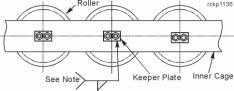
ROLLER CIRCLE ADJUSTMENT
Roller Circle Assembly
Roller circle adjustment is required to prevent damage to the rollers, roller cage, or rails if vibration, popping, snapping, or crackling occurs during rotation. Rapid wear and/or damage to roller circle components results from any one or a combination of the following:
• Roller spacers misaligned. • Roller spacers or capscrews worn. • Cage diameter too large or out of round. • Incorrect roller or rail hardness. • Improper machine ballast. • Continuous operation on a steep grade.
ADJUSTMENT PROCEDURE
1. Place the machine on a level work area. the roller circle capscrews should be uniformly snug ~ not tight and not loose.
2. Slowly rotate the machine two revolutions with the dipper extended just above grade at its maximum radius.
3. Check to see that all the rollers are seated against the thrust rail. If not, further loosen the circle capscrews and repeat step two.
4. Check the gap between each roller and its thrust washer. If it is not a .12 inch nominal gap at all rollers, then wrap a chain or wire rope sling around the circumference of the outer roller circle cage and draw it up until the gap at each is .12 inch nominal. Loosen the roller circle capscrews further if needed.
5. Tighten the roller circle capscrews to 210 Ft.Lbs. These should be tightened in the circle at those rollers which are engaged between the upper and lower rails. Rotate the machine to position the successive rollers between the rails for tightening. Remove the tensioning device from around the outer circumference of the roller circle.
6. Rotate the machine up to working speed, plugging and reversing it several times. Shut down and check that the rollers are seated against the thrust rail and that the gap between each roller and its thrust washer is .12 inch nominal.
7. Re-tighten all the roller circle capscrews after one full shift of operation. With the dipper extended, tighten the capscrews at the rollers that are engaged between the upper and lower rails. Rotate the machine to position the successive rollers there for tightening.
RUN-IN PROCEDURE FOR THE ROLLER CIRCLE
For the first few days after installing a new roller circle or new rollers, rotate the machine 360o every four hours. Check the torque of the roller capscrews at the end of this period and adjust as required.
It is normal practice to rotate the upper frame one full revolution (360o) at the start of each shift to relocate the rollers 180o so they wear evenly.
ROLLER CIRCLE SEGMENT REMOVAL
1. Place the machine on a level work area. Rotate the machine so that the segment to be replaced is near the front or the rear of the machine.
2. If a rear segment is to be removed, raise the rear of the machine with jacks (or by hoisting the dipper into a bank). If a front segment is to be removed, jack the boom by crowding the dipper into the ground.
DANGER: BLOCK THE MACHINE IN PLACE AFTER RAISING THE FRONT OR REAR UPPER RAILS OFF THE ROLLER CIRCLE. SHUT DOWN THE MACHINE, SET THE BRAKES AND DISCONNECT THE POWER SUPPLY. Failure to comply could result in serious injury.
3. Remove the 4 splice bars (2 inner and 2 outer) from the ends of the segment.
4. Replace the through capscrews in the end rollers. Replace the nuts on the ends of the capscrews after the splice bars are off the segment.
5. Carefully lift the roller segment (approx. 1300 Lbs.) up off the lower rail and move it away from the machine.
NOTE: This segment removal provides access to the upper and lower roller rails for rod and bolt tightening and/or replacement. The entire roller circle can also be replaced by systematically removing a segment, replacing the rollers, reassembling the segment into the circle, rotating the machine to the next segment, and so on until the entire roller circle is installed.
6. Reassembly is the reverse of disassembly.
a. Refer to “Roller Circle Adjustment Procedure” above.
b. Tighten the roller capscrews as specified in the procedure after the roller circle assembly is situated correctly.
c. Refer to “Roller Replacement” for lubrication and matching of adjacent roller diameters.
ROLLER CIRCLE - ROLLER REPLACEMENT
NOTE: Replace a broken or flat roller immediately.
1. Place the machine on a level work area. Rotate the machine so that the roller to be replaced is near the front or the rear of the machine.
2. If a rear roller is to be removed, raise the rear of the machine with jacks (or by hoisting the dipper into a bank). If a front roller is to be removed, jack the boom by crowding the dipper into the ground.
DANGER: BLOCK THE MACHINE IN PLACE AFTER RAISING THE FRONT OR REAR UPPER RAILS OFF THE ROLLER CIRCLE. SHUT DOWN THE MACHINE, SET THE BRAKES AND DISCONNECT THE POWER SUPPLY. Failure to comply could result in serious injury.
4. If enough room exists above the roller cage to allow passage of the roller, remove the roller directly:
a. Remove the capscrews from the roller to be replaced.
b. Lift the roller with bushing and thrust washer from the cage.
c. Remove the thrust washer as soon as it clears the inner cage.
5. If not enough room exists to allow passage of the roller above the roller cage, remove the outer cage:
a. Remove the 2 outer splice bars from the ends of the roller segment containing the roller to be replaced.
b. Remove the capscrews securing the rollers within the roller circle segment containing the roller to be replaced.
c. Remove the outer cage member, then lift the roller with bushing and thrustwasher from the roller circle.
d. Remove the thrust washer as soon as it clears the inner cage.
7. Place the roller on some cribbing at ground level. Remove the spacer and bushing.
8. Inspect the parts and replace as needed.
Reassembly is the reverse of disassembly:
a. The diameter of the new roller must be within ±.001 inch of adjacent rollers. Measure the diameter of its adjacent rollers and grind the new roller(s) to match.
b. Coat the nylatron bushing, thrust washer and bore of the roller with a winter grade of
MPG.
c. With the roller seated against the thrust rail, the gap between the thrust washer and roller is to be .12 inch nominal. Refer to “Roller Circle Adjustment Procedure” above.
d. Tighten the capscrews to 210 Ft.Lbs.
CRAWLER BELTS
The Crawler Belts contact the ground and transfer the entire weight of the machine from the truck frame to the ground. Each belt is an endless shoe assembly that is moved by the propel machinery around the crawler side frame. One belt on each crawler consists of 47 cast alloy steel, noncleated, double-pin connected shoes. The pins are retained in the shoes by lock bolts.
All the shoes assemble into the belt so that the male lugs on each shoe are toward the front of the machine when the shoe is on the bottom of the crawler frame.
CRAWLER BELT MAINTENANCE
1. Replace any missing or broken shoe pin lock bolts immediately.
2. To remove old shoe pins - drive them out if possible, burn them out if necessary.
3. Annually (5000 hrs.) remove any metal flow from the roller path on each shoe that interferes with belt motion. Use arc air to within .125 inch of final surface, then grind the remainder.
4. Monitor the fit of the shoes or belt to the drive tumbler monthly (420 hrs.)
• Record wear rate.
• Replace shoes or rebuild drive lugs as needed. • Replace the tumbler or rebuild wear areas as needed.
5. Replace or rebuild the slide bars on the crawler side frame BEFORE the drive lugs on the shoes touch the top of the crawler.
IMPORTANT! PROPERLY ADJUSTED BELTS REDUCE THEIR WEAR RATE AND PROLONGS THEIR SERVICE LIFE!
CRAWLER BELT TENSION ADJUSTMENT
1. Propel the machine forward on level ground until most of the slack in the crawler belt is on top of the crawler.
2. Safely park the machine. Remove the auto lube line from the end of the front idler shaft.
3. Position 2 identical hydraulic jacks to the rear of the adjusting blocks on each side of the front idler in the crawler side frame. Seat the jack ram into the counterbore provided in the adjusting block.
4. Remove the 2 shim retainer bars on each side to free the shims, and remove the shims from the storage space in front of each adjusting block.
5. Extend both hydraulic jacks in unison to move the front idler assembly forward to tighten the belt. Do not permit the adjusting blocks to mis-align in the side frame.
6. Tighten the belt until all slack is removed and the crawler shoes start to lift off any slide bar.
7. Insert shims into the space on each side behind the adjusting blocks until a gap of 1.5 inches exists between the shims and the blocks.
NOTE: Shims of the same thickness and quantity must be used in the space on each side to maintain correct idler alignment in the crawler.
8. Release both hydraulic jacks and remove them from the crawler.
9. Put the remaining shims in the storage space in front of each adjusting block. Reassemble the shim retainer bars to the crawler. Reconnect the auto lube line.
NOTE: Both crawler belts should be adjusted to the same tension and the same overall length. This is to insure that the machine will propel in a straight line. The machine will have a tendency to turn toward the shorter belt when propelling forward.
NOTE: Moving the adjusting blocks 1.00 inch results in a belt adjustment of 2.00 inches.
Crawler Belt Tension Adjustment
Correct Belt Tension
NOTES: • BEFORE the drive lugs on the shoes touch the top of the crawler frame, replace or rebuild the slide bars to their original height.
• To check for the correct belt tension - while propelling the machine insure that the crawler shoes effectively engage the drive tumbler. This is achieved when their is a minimum of radial shoe movement as it enters the load area of the drive tumbler.
CRAWLER SHOE REPLACEMENT
DANGER: STORED ENERGY! SECURE THE CRAWLER BELT BEFORE SEPARATING IT SO UNEXPECTED MOVEMENT UNDER ITS OWN WEIGHT IS PREVENTED. Failure to secure the belt could result in bodily injury or death.
1. Park the machine safely on a level work area with the shoe to be replaced at the front idler at the belt separation point.
2. Add blocking between the top of the crawler frame and the shoes to remove any slack in the belt.
3. Using hydraulic jacks, remove any belt tension by removing the shims behind the adjusting blocks on each side of the front idler shaft.
NOTE: Propel the machine slightly back and forth to unseat the adjusting blocks rearward in the frame slots if they do not move on their own.
3. Block or support the shoe below the one to be removed. To separate the belt, remove the pin locking hardware and the pin from 2 places on the bottom of the shoe to be removed.
4. Sling and support the shoe to be removed and then remove the pin locking hardware and the pin from 2 places on the top of the shoe to be removed. Remove the shoe from the belt.
5. Position the new shoe into the belt. To fasten one end of the new shoe to the belt, insert the pins and locking hardware in 2 places to secure one end of the shoe. Remove the sling.
6. Align the other end of the shoe to the existing shoe to close the belt. Install the pins and locking hardware in 2 places to secure the shoe. Tighten the capscrews retaining all 4 pins removed to 1045 Ft.Lbs.
7. Remove the blocking and adjust the belt tension.
CRAWLER BELT REPLACEMENT
1. Park the machine in a level work area. Assemble the new belt forward of the machine, in line with the one to be replaced.
2. Add blocking between the top of the crawler frame and the shoes to remove any slack in the belt.
3. Remove any belt tension. To separate the belt, at the lowest point forward of the front idler, remove the locking hardware and pin from 2 places on the shoe.
4. Connect the new belt to the front shoe under the front idler roller at the separation of the old belt. Install both pins and their locking hardware and tighten the capscrews to 1045 Ft.Lbs.
5. Attach a wire rope to the upper portion of the old belt at the separation point, then to a truck or dozer.
6. Pull on the top portion of the old belt to maintain engagement with the shoe lugs on the drive tumbler and SLOWLY propel the machine forward until the new belt has replaced the old on the crawler. Park the machine.
7. Disconnect the old belt from the new and remove it from the work area. Pin the new belt together at the front idler.
8. Adjust the belt tension.
Crawler Belt and Shoe Replacement
CRAWLER SIDE FRAME ASSEMBLY
The Crawler Side Frame assembly provides the motion path and support structure for each crawler belt. Each assembly bolts to the truck frame structure and contains the propel machinery to drive its respective belt.
Each side frame assembly consists of the following components:
• 8 Load rollers which transfer machine weight to the belt. • 1 Front idler roller.
• 1 Rear idler roller.
• Drive tumbler shaft.
• Planetary propel gearcase, totally enclosed with right angle input. • Propel motor with a single-disc, spring-set, air-released brake. • Heavy duty fabricated frame structure with slide bars to guide the belt.
CRAWLER SIDE FRAME MAINTENANCE
Maintenance and inspection requirements for each crawler side frame includes:
• Check the tension of the rod bolts joining the crawler side frame to the truck frame. • Inspect the crawler side frame structure for cracks quarterly (1250 hrs). • Inspect lubrication coverage daily. • Check auto lube injector operation daily.
• Change the oil in the gearcase yearly (5000 hrs) or as determined by lab analysis of oil samples.
Crawler Assembly - Right Shown, Left Opposite
PROCEDURE for USE of MECHANICAL TENSIONER ON CRAWLER RODS
NOTES:
• The Standard Preload for this Mechanical Tensioner (3.0 Dia Rod) —
• Tighten the Jackbolts on the tensioner to 233 Ft.Lbs. (428,400 Lbs. Clampload).
• The rod threads should be clean and the fit of the tensioners and nuts on the rods should be very free. This is to allow for stretch of the rod during tensioning.
• Perform Steps #2-#5 below, completely, for each Mechanical Tensioner — in the tightening sequence indicated in the overall view in the figure.
• Due to stretching of long bolts and rods, Steps #4 and #5 below may have to be repeated to obtain the final preload.
• Assemble all rods to the STANDOUT DIMENSION as shown in the figure before tensioning.
• After 20 hours of machine operation, repeat Step #5 below for all the rods, in the sequence indicated.
• Annually, repeat Step #5 below for all the rods, in the sequence indicated.
Initial Tensioning:
1. To seat the threads and eliminate clearances, use a small wrench to tighten the jackbolts on the mechanical tensioner to 10% of the final torque required (Approx. 23 Ft.Lbs.). Tighten the jackbolts in the sequence indicated in Figure #1.
2. Switch to a torque wrench and tighten the jackbolts to 50% of the final torque required (Approx. 117 Ft.Lbs.), again using the sequence in Figure #1.
3. Re-tighten the jackbolts to 75% of the final torque required (Approx. 175 Ft.Lbs.) — however, use the sequence in Figure #2.
Final Tensioning:
4. Tighten the jackbolts to 110% of the final torque required (Approx. 256 Ft.Lbs.) using the sequence in Figure #2.
5. Tighten all the jackbolts to the final torque required (100%, Approx. 233 Ft.Lbs.) using the sequence in Figure #2.
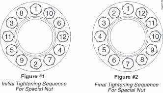
Connecting Rods - Crawlers to Truck Frame
SLIDE BAR REPLACEMENT
Eight Cast Manganese Slide Bar Caps guide the crawler belt over each crawler side frame. These slide bar caps are welded to 4 supports on each crawler and are intended to be replaced when worn.
The procedure for replacement is as follows:
1. Park the machine in a level work area.
2. Remove all tensioning shims in the front idler. This will provide as much slack as possible in the crawler belt. Raise the shoes over the slide bar(s) to be removed at least 6.5 inches.
3. Remove the 6 welds which attach the slide bar cap to be removed to its support and remove the slide bar cap.
4. Grind the new slide bar cap as required for a proper fit.
5. Install the new slide bar cap and weld in place. Refer to the figure below.
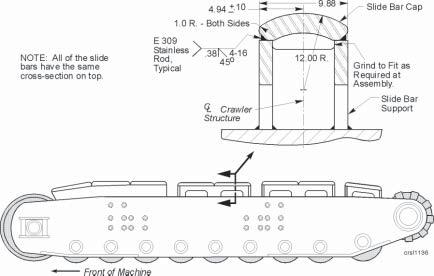
Crawler Mounted Slide Bars
Crawler Front Idler Assembly (Left Shown, Right Opposite)
CRAWLER FRONT IDLER ROLLER ASSEMBLY
The front idler roller carries the machine weight in conjunction with the load rollers. The roller turns about the idler shaft on bronze bushings. The idler shaft mounting consists of a pair of adjusting blocks which can be moved to the front or rear to compensate for crawler belt wear. Shims located on either side of each adjusting block are used to maintain the roller position. To remove the front idler:
1. Park the machine in a level area leaving several inches of clearance under the front idler to be removed.
2. Rotate the revolving frame to provide crane access to crawler belt and idler.
3. Remove the shim retainer bars, lube lines and shims ahead of the adjusting blocks.
Front Idler Assembly - Section View 4. Using the jacks provided, push the adjusting blocks on both sides of the idler shaft forward to allow removal of the remaining shims.
NOTE: When using jacks to move the adjusting blocks, pressurize and release both jacks at the same rate to prevent binding of the idler shaft.
5. Release the belt tension by slowly releasing the jack pressure to allow the adjusting blocks to move to their rear-most position.
6. Separate the crawler belt behind the top of the idler and lay the forward crawler shoes on the ground in front of the crawler.
DANGER: SECURE THE CRAWLER BELT BEFORE SEPARATING IT SO UNEXPECTED MOVEMENT UNDER ITS OWN WEIGHT IS PREVENTED. Failure to secure the belt could result in bodily injury or death.
7. Support the idler (approx. 5100 Lbs.) with a crane.
8. Remove the shaft locking pins, the adjusting block screws (4 places per block) and the adjusting blocks.
9. Use the tapped hole in the CENTER of either end of the idler shaft to remove the shaft.
CAUTION: STAND CLEAR OF THE AREA AS THE SHAFT IS REMOVED. The Thrust Washers and Shims are fastened to the adjusting blocks with long hex-socket-head screws. THESE PARTS MAY FALL OUT AS THE SHAFT IS REMOVED.
NOTE: Do not use the off-center lube supply holes at one end of the shaft for removal.
10. Lift the idler clear of the crawler frame.
11. Inspect all parts for wear or damage. Replace or repair as required.
Installation of the front idler is the reverse of removal.
NOTE: -Install the idler shaft with the 2 lube grooves toward the front of the crawler and the lube supply holes toward the CL machine (Inboard). -If removed, install the thrust washers with their lube grooves toward the ilder roller. Verify that the proper running gap exists between the thrust washer and the idler on each side of the idler.
-After installation, lubricate and check auto-lube. Adjust belt tension. Refer to proper procedures in this section of the manual.
LOAD AND IDLER ROLLERS
The Load and Rear Idler Rollers are located at the bottom of each crawler side frame. The load rollers and rear idler distribute the machine weight on the crawler belt.
Each of the load rollers and rear idler roller turn on a fixed shaft secured in the crawler side frame by a lock collar and pin. Each roller is fitted with a bronze bushing.
Thrust washers are located between the rollers and inner frame bosses to retain lubrication and prevent the entry of dirt.
ROLLER REMOVAL OR REPLACEMENT
To remove a roller from the crawler side frame:
1. After a pit has been prepared, position a handling fixture under the roller for support when the shaft is removed.
2. Propel the machine forward to a position where the roller to be removed is directly over the hole. Separate the belt by removing the lock bolts. Lower each end of the belt into the pit exposing the roller for removal.
3. Disconnect the auto lube line from the end of the roller shaft. Plug the line to prevent dirt entry.
4. Remove the shaft retaining bolt.
5. Drive or pull the shaft out of the crawler frame, being careful to support the roller on a handling fixture, jack or cribbing. Remove the thrust washers as they come free.
The same procedure can also be used to remove the rear idler roller.
To install or replace a load or rear idler roller:
1. Position the replacement roller in the pit on some cribbing, a handling fixture or jack.
2. Start shaft through the outside crawler side frame member. When the shaft begins to exit the other side, install the thrust plate.
3. Raise the roller or idler into position and continue to drive the shaft through the roller or idler.
4. As the shaft exits the roller, install the other thrust plate.
5. Continue to drive the shaft through the crawler frame until the bolt retainer aligns with the hole in the collar.
NOTE: Install the load or idler roller shafts with their lubrication hole toward the front of the machine. The punch mark on the end of the shaft indicates the lube hole location.
6. Install the lock bolt.
7. Install and purge the automatic lube lines. Check the lube system operation and reinstall the guards.
Since the rollers are captured between the sides of the crawler frame, removal or replacement requires the separation of the crawler belt and the lowering of the roller below the crawler side frame. This is best accomplished by digging a pit to the dimensions shown in the following chart:
Pit Size Height Width REAR IDLER 55 inches 79 inches
LOAD ROLLER 39 inches 63 inches
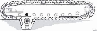
Load Roller Removal
PROPEL ASSEMBLY
NOTES:
Propel Drive Shaft Assembly ~ Exploded View
1. After a thorough cleaning, coat both the internal and external splines and surfaces indicated with Molylub-Alloy grease paste (P.C. No. 480206-3) or equal.
2. The 6 socket head capscrews in the bearing cartridge of the Main Propel Shaft are present only to hold the subassembly of the cartridge and bearing to the shaft. They are not to be removed after installation, or during removal of the Main Propel Shaft.
The drive shaft transmits propel effort from the planetary gearcase to the crawler belt. Anti-friction bearings support the assembly at each end.
Propel Drive Shaft Assembly ~ Section View
INSTALLATION NOTES
1. Install the retainer with the lube hole on the horizontal centerline of the propel shaft and in line with the access hole.
2. After thorough cleaning, coat the splines and surfaces with Molylube grease paste (P/ N 480206-3).
3. Pack the rear of the spline cavity with 1 pint grease (P/N 280206-3), prior to installing the shaft assembly.
4. Shim Procedure For Gap “A”:
A. After bearing installation, assemble the retainer to the shaft and tighten the capscrews to 225 Ft.Lbs. for gap measurement.
B. Measure through the 3 small holes in the retainer with a depth micrometer to determine the distance from the outer face of the retainer to the end of the shaft.
C. Remove the retainer and measure the retainer thickness at the 3 small holes.
D. Take the average of the 3 measurements from Step B and subtract the average of the 3 measurements from Step C. From this difference subtract .001-.004 inch to obtain the shim thickness.
E. Install the shims and tighten the capscrews to 905 Ft.Lbs.
5. Shim Procedure For Gap “B”:
Add the required amount of shims at Gap “C” to obtain a gap of .08 ±.02 inch at Gap “B”.
6. Shim Procedure For Gap “D”:
A. Install the retainer and tighten the capscrews to 225 Ft.Lbs. for the gap measurement.
B. Measure the gap at 3 places equidistant around the O.D. of the retainer.
C. Take the average of the 3 measurements and subtract .001-.004 inch to obtain the shim thickness.
D. Install the shims and tighten the capscrews to 905 Ft.Lbs.
E. Fill the bearing cavity with Mobilux EP2 or equal grease (P.C. No. 380900-5).
7. If these shims are 2-piece, install with the split line horizontal and seal the split with RTV.
MAIN PROPEL DRIVE SHAFT REMOVAL
1. Park the machine safely on a level work area.
2. Rotate the revolving frame to gain access to the propel machinery.
3. Release the tension in the crawler belt to unpin the belt.
4. Have a qualified electrician disconnect the trail cable from the machine and move it out of the way.
DANGER: HIGH VOLTAGE! Only qualified personnel are permitted to perform this operation. Failure to comply could result in bodily injury or death.
5. Remove the walkway from the front of the wing, above the propel machinery.
6. Separate the belt on top of the crawler, forward of the drive tumbler.
DANGER: Secure the belt before separating it so that it cannot move unexpectedly under its own weight. Failure to do this could result in personal bodily injury.
7. Lift the belt from the drive tumbler and lay it on the ground.
8. Mark the tumbler and the shoe under it with a visible mark (paint) so that the tumbler can be repositioned to the belt in same location.
9. Remove the guard from the propel motor coupling and disassemble the coupling.
10. Support the propel gearcase (approx. 15,800 Lbs.) with a crane.
11. Unbolt the propel gearcase and remove it. Store in a clean area.
12. Remove the lube line to the inboard propel bearing at the inside of the gearcase housing.
13. Disconnect and plug the lube line to the outboard bearing retainer. Remove the retainer with its shim pack from the end of the main propel shaft. Support the tumbler with the crane.
14. Pull the outboard bearing carriage from its bore using 3 - M24 x 3 x 200 jack screws in the tapped holes provided in the cartridge flange.
15. Remove the retainer plate from the outboard end of the tumbler shaft.
16. Use the spacer between the bearing race and shaft shoulder as a puller. Six tapped holes (M20 x 25 ) are provided to attach the threaded rods and hardware required. Hydraulic expansion of the inner race is also provided to ease the pulling force. Attach the hydraulic pump provided with the machine to the .25 inch hole in the end of the drive shaft. Use hydraulic pressure and pulling force simultaneously to remove the bearing race.
17. Remove the 18 - 1 Inch capscrews which secure the cartridge and retainer to the crawler.
DO NOT remove the 6 capscrews which secure the retainer to the cartridge.
18. Install a pulling eye in the ( M42 x 4.5 x 44 mm ) tapped hole provided and using the fixtures shown, remove the drive shaft assembly toward the CL machine.
Fixture for the Main Propel Shaft
19. Lift the tumbler clear of the crawler after the shaft has been removed.
20. Inspect all parts for damage or wear. Replace or repair as required. Refer to the “Main Propel Shaft” for disassembly and rework.
21. Reassembly is the reverse of disassembly.
a. Replace all seals and bearings.
b. Coat the internal and external spline surfaces and all pilot surfaces with Molylub-Alloy grease paste (P/N 480206-3) or an equivalent.
c. The inner race for the outboard bearing on the main propel shaft may be heated to fit it to the shaft. Use a dry heat source and do not heat the race over 250o F (121o C). Allow the race to cool to ambient temperature before installing the rest of the bearing.
d. Lube access on both bearing retainers of the main propel shaft must be installed on a horizontal centerline toward the front of the crawler.
e. Shim the gaps as indicated on the accompanying sketches.
f. Pack the rear of the spline cavity in the propel gearcase for the main propel shaft with 1 pint of Molub-Alloy grease paste (P/N 480206-3) or an equivalent.
g. Fill the bearings and cavities manually with MPG lube at assembly. Reconnect and purge the lube line.
h. Observe the match marking when installing the tumbler and propel gearcase, and when assembling the propel motor coupling.
j. Propel motor coupling reassembly can be assisted by releasing the brake with the manual override on the air control valve to allow the motor shaft to rotate freely.
22. Reconnect the crawler belt and adjust the belt tension. Reinstall the walkway to the front of the wing.
23. Have a qualified electrician reconnect the trail cable to the machine.
DANGER: HIGH VOLTAGE! ONLY QUALIFIED PERSONNEL ARE PERMITTED TO PERFORM THIS OPERATION. Failure to comply, could result in bodily injury or death.
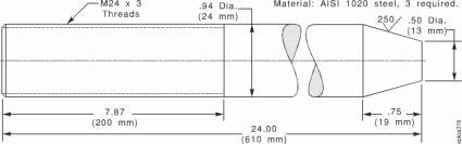
Propel Shaft Pilot Rod

Propel Shaft End Support
Details for the Main Propel Shaft Fixture
MAIN PROPEL SHAFT - DISASSEMBLY
1. Remove 2 locking capscrews from the bearing nut, and unscrew the bearing nut from the shaft using the special wrench provided with the machine.
2. Lift the lip seal from the back face of the bearing cartridge, if it is still in place.
3. Remove 6 hex socket head capscrews holding the retainer to the cartridge.
4. Remove the retainer and seal spacer from the shaft.
5. Pull the cartridge from the bearing in the opposite direction.
6. Use a bearing puller to remove the bearing from the shaft.
7. Remove the bearing spacer from the shaft.
8. Inspect the final spacer that may remain next to the splines on the shaft. Remove if required for replacement.
9. Inspect all parts and replace as required.
10. Reassembly is the reverse of disassembly:
a. The double tapered bearing may be heated for assembly to the shaft. Use a dry heat source and do not permit the temperature of bearing to exceed 300oF (149o C). Allow the bearing to cool to ambient temperature before assembling any other parts to it.
b. Install the bearing retainer and new seal without shims. Shim the gap at the retainer/ cartridge as indicated in the accompanying sketch.
c. Fill the bearing cavity with MPG lube at assembly.
d. Spray the lip seal area with Molylube 1200 AR (P/N 170025-1) or an equivalent at assembly.
11. Assemble the main propel shaft into the tumbler and crawler.
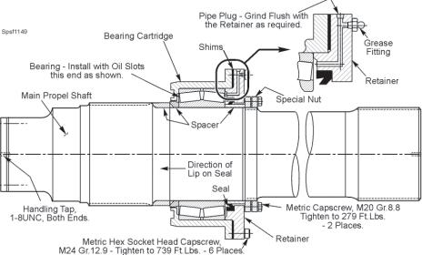
Main Propel Shaft ~ Section View
NOTES:
1. If the bearing is heated for assembly purposes, do not exceed 300oF (149oC).
2. After installing the bearing and bearing cartridge, pack the bearing with MPG (P/N 380900-5).
3. Shim Procedure:
a. Install the retainer and tighten the capscrews to 179 Ft.Lbs. for gap measurement.
b. Measure the gap at 3 places equi-distant from each other around the O.D. of the retainer.
c. Take the average of the 3 measurements and subtract .001-.004 inch to obtain the shim thickness.
d. Install the shims and tighten the capscrews to 739 Ft.Lbs. If the shims are 2-piece, install them with the split as close as possible to the lube hole and seal the split with RTV.
TUMBLER REBUILD PROCEDURE
The drive tumbler can be repaired by a buildup of weld applied to the 9 drive lugs. To build up the lugs, proceed as follows:
1. Prepare a template as indicated in the sketch below. The template can be made of sheet metal, wood or template paper. Contact Bucyrus for details.
2. Clean the tumbler of all spalled or loose material, grease and contaminants. Use a grinder to remove imperfections. DO NOT USE A TORCH.
3. Preheat the tumbler rim to 550 oF (273 oC). Keep the hub area below 200 oF (93 oC). Maintain this temperature during welding.
4. Hold a medium length arc - slight weaving action permitted but keep it to a minimum to prevent local overheating. Weld beads must be applied adjacent to each other without removing the slag. This will result in a smooth overlay. Remove the slag between layers, maximum of 3 layers permitted.
5. Weld to within .19 inch of the final contour with weld rod that conforms to AWS E-9018. Use only low hydrogen electrodes.
6. Finish contour the buildup using Hobart “Tufanhard 550” electrode, or its equivalent. Use small diameter electrodes and deposit with stringer bead technique.
7. Allow the tumbler to cool slowly.
8. If needed, grind to a final lug contour.
Crawler Tumbler Rebuild
Crawler Drive Tumbler Rebuild Template
PROPEL MACHINERY
The Propel Machinery is interchangeable between the left and right crawler assemblies. Both the planetary gearcases and motors mount inboard at the rear of the crawlers. Before installing a left gearcase onto a right crawler side frame, exchange the oil breather with oil drain and exchange eye bolt with screw plug. (As the same gearcase can be used on either the right or left side note that following the previous instructions, either hole can be used as an oil drain.) The drive motors are also interchangeable between the right and left crawler frames. A disc brake mounts on the rear of each motor frame.
General maintenance and inspection of the propel machinery includes:
1. Inspection of the gearcase and electric motor mounting bolts.
2. Check the gearcase oil level daily by removing the oil level plug in the gearcase.
3. Change the oil in gearcase annually or as indicated by lab test analysis. Flush the gearcase before refilling with oil. (See Lubrication Section.)
4. Inspect the motor coupling quarterly for lube level and keep full.
5. Lubricate the motor bearings semi-annually with EMG (Electric Motor Grease). Application of grease should be performed by qualified personnel as an excess could cause motor failure.
6. Inspect the operation of the brakes daily. Monitor wear rate of friction disc. Replace when wear ring indicates lining is worn out. For more detailed information on the description and maintenance of the propel brakes, see Section 7 - ENGINEERING DATA, in this manual.
PROPEL GEARCASE REMOVAL
To remove the left or right Propel Gearcase use the following procedure:
1. Park the machine on a level work area.
2. Rotate the upper frame to gain access to the propel gearcase with a crane or hoist.
3. Disconnect the trail cable from the machine and move it out of harms way.
DANGER: HIGH VOLTAGE! A QUALIFIED ELECTRICIAN SHOULD DISCONNECT THE TRAIL CABLE. Failure to comply could result in bodily injury or death.
4. Remove the cable reel if furnished with the machine.
5. Drain the oil from the gearcase.
6. Remove the guard from the propel motor coupling.
DANGER: STORED ENERGY! Once grid is removed, machinery is free to rotate and brake will no longer hold. Gearing or drum must be blocked prior to doing any maintenance to prevent unwanted movement. Death, serious injury, or damage to the machine can result from failure to take proper measures to prevent movement due to release of energy.
7. Open the propel motor coupling and remove the spring grid. Note the match marking on the coupling covers.
8. Remove the inspection cover from the housing on the crawler bell housing for viewing the main propel shaft/gearcase junction.
9. Support the gearcase (approx. 15,800 Lbs.) with a crane line through the lifting eye on the gearcase.
10. Remove all 36 capscrews that fasten the gearcase to the crawler side frame bell housing. Match marks on the gearcase and crawler bell housing flange are for coupling alignment assistance if the SAME gearcase is reinstalled.
11. Use 3 of the removed capscrews in tapped holes in the flange of the gearcase as jacking screws to evenly withdraw the gearcase from the pilot bore in the crawler bell housing.
12. Remove the gearcase from the splines of the main propel shaft and lift it away from the crawler to some cribbing.
13. If a new or exchange gearcase is to be installed, use a bearing puller to remove the coupling hub from the input shaft.
NOTE: The planetary gearcase design requires close tolerances and special tools for disassembly and rebuild. DO NOT ATTEMPT TO DISASSEMBLE THESE UNITS WITHOUT A QUALIFIED FACTORY REPRESENTATIVE PRESENT.
PROPEL GEARCASE INSTALLATION
The installation procedure for the propel gearcase is as follows:
1. Install the coupling hub onto the gearcase input shaft. The Coupling hub should be heated to assist installation onto the shaft. Use a dry heat source and DO NOT permit temperature of the hub to exceed 350o F (177o C). Allow the hub to cool to ambient before assembling any other coupling parts.
2. Install the a new face seal onto the propel shaft as shown in the sketch.
3. Pack the rear of the spline cavity in the propel gearcase for the main propel shaft with 1 pint of Molub-Alloy grease paste (P/C 480206-3) or equivalent.
4. Coat the internal and external spline surfaces and all shaft pilot surfaces with Molub-Alloy grease paste or equivalent.
5. Install the gearcase by engaging the splines of the gearcase with the main propel shaft and the pilot register of the gearcase with the crawler housing. Install the spacer and 36 fasteners and tighten to 7,380 Ft.Lbs.
NOTE: Align the match marks if the same gearcase is being reinstalled. This will minimize the time required to align the coupling. If a NEW gearcase is being installed, add new match marks after the gearcase has been installed and the coupling aligned.
6. Fill the gearcase with the proper lubricant to the specified capacity. Refer to Section 3 LUBRICATION, in this manual. Be sure to install the breather and case plugs.
7. The reassembly of the propel motor coupling can be assisted by releasing the disc brake with the manual override on the air control valve. This will allow the rotation of the motor shaft.
8. Align the motor coupling per the specifications in Section 6 - BRAKES AND COUPLINGS, in this manual. Install the grids and cover.
9. Fill the propel motor coupling to the recommended level with special long term grease (P/C 295148-7).
10. Install the cable reel, if furnished, with the machine and reconnect the trail cable.
DANGER: HIGH VOLTAGE! - RE-CONNECTION OF THE TRAIL CABLE SHOULD ONLY BE PERFORMED BY A QUALIFIED ELECTRICIAN. Failure to comply could result in severe bodily injury or death.
NOTES:
1. Bearing spacer - grind to obtain a preload of .002 inch.
2. Bearing spacer - grind to obtain a preload of .001 inch.
3. Cartridge spacer - Grind to fill the gap after adjusting the tooth pattern.
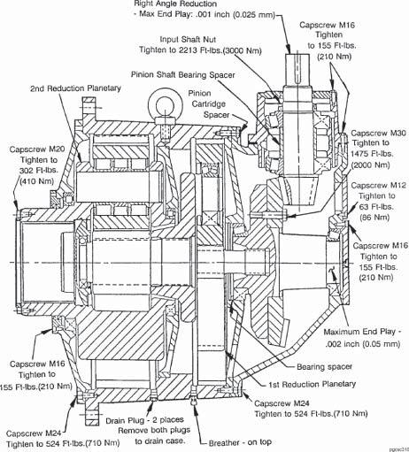
Propel Gearcase ~ Section View
PROPEL PLANETARY GEARCASE
The propel gearcase assembly includes three reductions - a right angle spiral bevel 1st reduction, a planetary 2nd reduction and a planetary 3rd reduction.
DANGER: STORED ENERGY! Gearing or drum must be blocked prior to performing maintenance in order to prevent unwanted movement. Death, serious injury, or damage to the machine can result in failure to take proper prevention measures.
To minimize down time, it is recommended that the gearcase be replaced as a complete unit, if a problem should develop within the case. If the case is to be disassembled, it should be taken to a maintenance shop for repairs.
NOTES:
1. The reduction spiral bevel (palloid) gear & pinion are manufactured as a matched set. Do not interchange or order separately.
2. When replacing the single row tapered bearings on the spiral gear shaft & pinion cartridge, the end play must be adjusted & new spacers ground to fit.
3. Check the 1st reduction tooth contact when a new bearing & new gears are installed.
4. Change the planet gears in sets of 3 only.
5. FOR LUBRICANT REPLACEMENT, Refer to Section 3 - LUBRICATION in this manual.
PROPEL MOTORS
DANGER: STORED ENERGY! Gearing or drums must be blocked prior to performing maintenance in order to prevent unwanted movement. Death, serious injury, or damage to the machine can result from failure to take proper prevention measures.
Each Propel Motor is bolted to a mounting pad located inside each crawler side frame. The motor output shafts are coupled to the planetary gearcase with grid type couplings. Coupling alignment is assisted with jacking screws located at six positions on the motor mounting pads. Each propel motor is equipped with a spring-set, air-released single-disc brake. See The ELECTRICAL SERVICE MANUAL for details of scheduled service to electric motors and equipment. Also: • Lubricate motor armature bearings with EMG every 500 hours. • Inspect the brushes every 250 hours and replace as required. • Observe the commutator condition each time the brushes are replaced. If it is discolored, grooved or otherwise damaged, consult the ELECTRICAL SERVICE MANUAL.
PROPEL MOTOR REMOVAL
1. Park the machine on a level work area and rotate the upper frame to gain access to the propel motor.
2. Have a qualified electrician disconnect the power from the machine and wiring from the propel motor.
DANGER: HIGH VOLTAGE! ONLY QUALIFIED PERSONNEL ARE PERMITTED TO PERFORM HIGH VOLTAGE ELECTRICAL SERVICE AND MAINTENANCE. Failure to comply could result in bodily injury or death.
3. Remove any dirt guards and/or cable support from around the motor and brake assembly.
4. Remove the guard over the motor coupling. Open the coupling and remove the grid.
NOTE: Match marking on the coupling covers is for use in reassembly.
5. Disconnect and plug the air supply at the disc brake.
CAUTION: RELEASE THE AIR PRESSURE TO THE BRAKE BEFORE DISCONNECTING THE AIR LINE. Plug the line immediately after disconnecting. Failure to comply could result in personal injury.
6. Support the motor with a crane line.
7. Remove the 4 capscrews and related hardware that fasten the motor to the crawler mounting pad. Lift the motor away from the machine to the cribbing. Secure the shims at the 4 motor mounting points at the time of removal so that they are available for reassembly.
8. To remove the disc brake from the propel motor, loosen the 6 capscrews that fasten the brake housing to the motor frame. Remove all but 2 of the capscrews. These should be opposite each other. Support the brake assembly and remove the remaining 2 capscrews.
NOTE: If the motor is to be replaced, remove the coupling hub and the brake rotor hub from each end of the electric motor armature shaft. For further information and a complete description of the propel brakes, refer Section 6 ~ BRAKES & COUPLINGS, in this manual.
PROPEL MOTOR INSTALLATION
The following procedure assumes that the propel motor being installed is new & that it has none of the additional parts required for the application.
1. Install the drive coupling hub & brake rotor hub onto the motor shaft. The rotor hub installs on the commutator end of the motor. Follow the hub/gear installation procedure in Section 7 ~
ENGINEERING DATA, of this manual.
2. Install the brake assembly so that the air inlet is at the bottom after the motor assembly is installed onto the machine. Again, refer to Section 6 of this manual for installation & adjustment.
3. Install the motor and brake assembly onto the crawler frame. Check the coupling alignment. With the motor shaft at midpoint of its axial float, the gap, angular offset & radial offset must all be within specification. Refer to “Grid Couplings” in Section 6 of this manual for specifications & mounting instructions.
4. If alignment is required, use the 4 jacking screws & mounting bolts to move the motor horizontally & the 2 jack screws under the motor to move it vertically. Once aligned, determine the shim thickness required and install the shims
6. Install the 4 motor mounting capscrews and related hardware.
7. Re-check the alignment. Reposition the shear blocks under the motor if required. Refer to shear block installation in Section 7 of this manual.
8. Install all guards, air lines & wiring.
CAUTION: ALL WIRING MUST BE DONE BY A QUALIFIED ELECTRICIAN.
CENTER PINTLE
DANGER: HIGH VOLTAGE!
EXTREME CARE MUST BE EXERCISED AT ALL TIMES WHEN PERFORMING MAINTENANCE IN THE CENTER PINTLE AREA. High voltage can cause serious or fatal injury. Installation, operation and servicing of components should be performed only by qualified personnel. ALWAYS DISCONNECT the electrical power BEFORE accessing the center pintle area.
The center pintle is a large diameter, hollow cylindrical forging with a flange at the top. It is threaded at the bottom with a lower nut used to hold it in place. A bronze coated steel core spherical thrust washer between the lower adjusting nut and the bottom surface of the truck frame provides a wear surface for pintle loads. The upper clamping collar at the top of the center pintle is doweled and bolted to the revolving frame to keep the center pintle from rotating.
The hollow pintle provides passage for air and grease lines and electrical cables from the revolving frame to the lower works using a swivel and collector ring assembly.
1. To inspect for worn thrust washers, rails, or rollers proceed as follows:
a. Every 3 months, check the amount of lift of the revolving frame at the rear of the machine. Engage the dipper in the bank at near maximum reach and apply hoist power. b. Measure the distance between the upper and lower roller rails at the rear of the machine. c. Subtract from this measurement the measured distance at the rear between the upper and the lower roller rails with the dipper on the ground.
d. If the difference in measurement is greater than 1/2 inch, the pintle lower nut must be adjusted to limit the amount of lift to between 3/16 and 1/4 inch. Refer to the Adjustment procedure.
2. The thrust washer, rails, or rollers may be worn sufficiently to require replacement rather than adjustment. If necessary, replace a worn thrust washer per the center pintle repair procedure and replace a worn roller and/or rail per the applicable repair procedure.
3. Clearance for free rotation of the revolving frame must be provided between the truck frame bushing and the sleeve. Such clearance, however, cannot be excessive or premature wear of the truck frame bushing or sleeve will occur.
To determine this clearance, proceed as follows:
DANGER: HIGH VOLTAGE! EXTREME CARE MUST BE EXERCISED AT ALL TIMES WHEN PERFORMING MAINTENANCE IN THE CENTER PINTLE AREA OF ELECTRICAL ENERGY. High voltage can cause serious or fatal injury. Installation, operation and servicing of components should be performed only by qualified personnel. ALWAYS DISCONNECT the electrical power BEFORE ACCESSING the center pintle area.
a. Disconnect the power to the machine. Enter the truck frame through the bottom access opening.
b. Remove the cover from the top of the truck frame and gain access to the space between the pintle and the rollers. Insert a feeler gauge between the sleeve and the bushing of the truck frame. Any measurement over 0.250" diametral clearance is considered excessive and replacement of the bushing and/or sleeve is necessary.
Center Pintle ~Section View
CENTER PINTLE ADJUSTMENT
To secure a loose center pintle sleeve which may be due to a worn thrust washer, roller, or rail, tighten the pintle lower nut as follows:
1. Enter the bottom compartment of the truck frame which will give access to the pintle lower nut adjusting pin. 2. Cut the lock wires and remove the capscrews attaching the lock bars to the lower nut. Remove the lock bars.
3. Pull down on the pin handle and rotate it 90° so that the pin can be moved into one of the slots in the lower pintle nut. 4. To calculate the required rotation of the center pintle to keep lift at the rear rails within the allowable range of 0.18" to 0.25", use the following formula:
R = (M-.25)576°
M = Measured lift at rear rails R = Rotation, in degrees, required at center pintle Example: If measured lift is .625", then R = (.625-.25)576° = 216°
The actual adjustments must be made in 90° increments to allow reinstallation of the nutlock bars. After determining the required rotation, select the degree of turn closest to 90°, 180°, 270°, or 360°. In the above example 216° is closest to 180°. When there is a choice of selecting a higher or lower degree of turn from the formula’s result, always use the lower degree turn to prevent overtightening of the pintle nut.
5. Install the lock bars and capscrews. Secure the capscrews with lock wire. 6. Disengage the adjusting pin. Make sure the pin handle is turned parallel to the pin and locked in the slot on the pin to prevent the pin from accidently reengaging the pintle lower nut. 7. Apply power to the machine and check the lift as described in Inspection.
CENTER PINTLE SLEEVE REMOVAL
Remove the center pintle sleeve and thrust washer through the top of the revolving frame as follows:
1. Propel the machine over a pit of sufficient depth to allow the center swivel housing to clear the truck frame.
2. Disconnect electrical power to the machine.
DANGER: HIGH VOLTAGE! EXTREME CARE MUST BE EXERCISED AT ALL TIMES WHEN PERFORMING MAINTENANCE IN THE CENTER PINTLE AREA OF ELECTRICAL ENERGY. High voltage can cause serious or fatal injury. Installation, operation and servicing of components should be performed only by qualified personnel. ALWAYS DISCONNECT the electrical power BEFORE ACCESSING the center pintle area.
3. Remove the coupling cover, the coupling, and shaft spacer. Disconnect, plug and tag all lube and air lines.
4. Remove hose guard and collector ring cover. Disconnect and tag electric leads.
5. Remove shoes, spacers and insulators from the collector ring housing.
6. Remove the control collector rings from the swivel shaft. Remove the swivel assembly retainer. Lift the swivel assembly and disconnect and tag the air and lube lines. Remove the retainer with swivel assembly attached. Remove the collector ring support and remove the support and collector rings as a unit.
7. Secure the swivel support at the top so that when it is removed it will not fall. Remove the access cover from the bottom of the truck frame and enter the truck frame. Disconnect and tag the electrical cables and tie them out of the way.
8. Remove the swivel support base from the truck frame and lower the swivel support with base out of the truck frame.
9. Remove the hoist drum shaft assembly. Refer to HOIST DRUM SHAFT in this section of the manual.
10. Remove the lock bars, lower nut, and thrust washer from the lower end of the pintle sleeve.
CAUTION: Be sure to apply a load to the center pintle lifting lug sufficient to lift the center pintle - before proceeding.
11. Remove the bolts, lockwashers and dowels that fasten the upper collar to the revolving frame. Remove the upper lock bars and their hardware. Remove the upper collar from the pintle sleeve.
12. Install the lifting lug, supplied with the machine, to the top of the pintle and connect the auxiliary winch to the lifting lug.
13. Using the auxiliary winch, lift the sleeve out of the revolving frame. Replace a worn or damaged sleeve with a new one. Check the pintle sleeve bushing for wear or damage. Replace if required. Check the truck frame around the pintle structure for cracks. If the pintle structure area needs repair, contact the Bucyrus International Service Department for instructions.
Center pintle sleeve installation is the reverse of disassembly.
NOTE: If the lower nut was burned apart for removal, reassemble the nut as follows:
a. Install new O-Rings on the alignment pins and insert the pins in the nut halves.
b. Clamp the two halves of the nut together. To install the new T-Bolts which have an interference fit of 0.47 to 0.53 inch to the nut, heat the T-Bolt to 900-950°F. Do not heat the T-Bolts to more than 1,000°F.
c. When installing the heated T-Bolts, be sure the chamfer is facing outward. Clamp the T-Bolts in-place with the T-Bolt retainers.
DANGER: HIGH VOLTAGE! Be sure the electrical lines are correctly connected and all connections are tight. Also make sure that the air and lube lines are connected to the correct outlets in the swivel assembly and that the connections do not leak.
COLLECTOR RINGS
There are three sets of collector rings on the machine - low voltage, propel and high voltage. The low voltage collector rings transfer power from the revolving frame back to the propel motors. The propel collector rings provide control to the propel motors and power for the propel blower motor.
High voltage collector rings, on the bottom of the revolving frame, transfer electric power from the truck frame to the revolving deck. Electric power enters the truck frame just below the propel motors and is transferred by means of collector ring shoes to the collector rings. The shoes are mounted between the cast center pintle hub and the swing rack.
COLLECTOR RING INSPECTION
Inspect the collector rings and shoes frequently for grease and contaminant accumulations on the rings, shoes, insulators and incoming wires.
Clean the collector rings and related parts with an approved solvent regularly to prevent high potential grounds. Make sure each shoe bears firmly against the collector ring. The shoes are spring-loaded to maintain constant contact.
CAUTION: Solvents may be toxic or flammable. Adequate ventilation must be provided to minimize fire and health hazards caused by using solvents for cleaning. Use away from sparks, heat or flame to prevent fire or explosion. Follow the manufacturer’s instructions.
Check the insulators for cracks or chipping and replace promptly if damaged. Verify that the screws securing the rings to the insulators do not protrude beyond the countersunk holes of the rings.
CAUTION: A cracked or chipped insulator or an excessive amount of contaminants may cause an electrical fault. This could result in death or serious injury.
COLLECTOR RING REPAIR
Repair of the collector rings involves replacement of damaged insulators or defective shoes. The collector ring life expectancy exceeds the life expectancy of the machine. However, To replace the insulators or shoes:
1. Disconnect electrical power to the machine.
DANGER: HIGH VOLTAGE! Do not access the collector rings unless power to the machine has been disconnected and locked-out. Only authorized personnel should service the collector rings.
2. Remove the attaching hardware securing the insulator or shoe to the mounting. Access to the shoes mounted to the truck frame is obtained by entering the truck frame through the bottom access opening.
3. Install new insulators or shoes. Make sure all electrical leads are securely attached to the shoes and collector rings.
CAUTION: Do not attempt to inspect the underside of the revolving frame until power to the machine is disconnected.
REVOLVING FRAME
Lube Room Jib Crane
CL Rotation Auto Lube Pumps and Reservoirs Remote Auto Lube Cabinet Front of Machine
Boom Foot Lugs
Air Compressor
AuxiliaryTransformer
Remote Hoist Cabinet Fire Protection Panel
SwingGearcase, Left
Lubrication Room
SwingBrake
SwingBlower
A-Frame Lugs, Rear Hoist PlanetaryGearcase Crowd Blower Crowd Brake Machine CL
Crowd Machinery Crowd Drum A-Frame Lugs, Front Remote MCC Rack Dipper TripTransformer Constant VoltageTransformer
Operator’s Ca b Outline
AuxiliarySeat
Crowd Motor
Center Pintle Hoist Drum Shaft
EmergencyLightPower Supply SwingBrake LightingTransformer
Hoist Machinery
Hoist CouplingShaft
Hoist Motor HighVoltageAccess
Remote Crowd Cabinet SwingBlower
Hoist Blower Hoist Brake SwingGearcase, Right Motor Control Center (MCC)
High VoltageCabinet
Utility Room
Operator’sSeat
Vertical BoardingLadder, Left Mine Signal Drive Power Transformer No.2 Remote BearingTemp. Cabinet
Power Skid Control Cabinet Remote Accuload Cabinet
Deck Plan
Drive Power Transformer No.1
M ine Signal CL Rotation
Boarding Stairs, Right
CABLE REEL
DANGER: HIGH VOLTAGE! WHEN ACCESSING THE CABLE REEL, THE TRAIL CABLE MUST BE DISCONNECTED FROM ITS POWER SOURCE. The trail cable carries high voltage which can cause serious or fatal injury.
DANGER: STORED ENERGY! System may be under hydraulic pressure which can cause severe personal injury or death. Shut down pump and relieve system of all pressure before removing components.
NOTE: The cable reel described here is an INDUSTRIAL WELDER & MACHINISTS, INC. cable reel. If the reel currently on the machine is from a different manufacturer, do not use the information given here, but refer to the manuals from that particular manufacturer.
The cable reel is used to store excessive lengths of trail cable, and also to retrieve and pay out cable as needed during machine propel. The cable reel should be checked daily to assure that it is working properly and that the trail cable is being spooled on and off the reel correctly.
Check for the following:
• The level wind mechanism works freely. • All drive chains are properly tensioned and well lubricated. • The control valve lever works freely. • The hydraulic reservoir for the proper level of fluid. Add fluid if required. Check the hydraulic lines for leaking. • All structural components for cracking.
This cable reel is designed to operate under a variety of conditions to suit the individual requirements that are required in each application. During initial operation some adjustments will be necessary to determine what line pull and speed are best suited for the current conditions.
Electric-hydraulic drive models are designed to operate at maximum pressure of 1000 psi continuously. In most applications, adjusting the hydraulic pressure to 600 psi has proven to be sufficient. Adjustments available are the pressure compensated pump, flow valve and relief valve.
HYDRAULIC DRIVE START UP INSTRUCTIONS
1. Fill the hydraulic tank with 10 gallons of premium grade hydraulic fluid and fill the pump case.
NOTE: Synthetic oil should not be used unless the cable reel was originally tested with it, or properly flushed. Premature pump failure may occur.
2. Place the control valve in the off (center) position. 3. The hydraulic pump is set for maximum flow. 4. Jog the electric motor and check pump rotation. If pump rotation does not correspond with the arrow on the pump, change the motor wiring. 5. Start the hydraulic system and let the oil circulate for 5 minutes. 6. Check all hydraulic connections for leaks. 7. Close the flow valve slowly, watching the hydraulic pressure. If the pressure exceeds 1000 psi, adjust pump pressure to a lower setting. 8. Close the flow valve and relief valves completely. Adjust pump pressure to 900 psi. 9. Loosen the lock nut on the relief valve adjusting screw. Open the relief valve until a pressure drop is noticed on the gauge. This is the relief valve operating pressure. Lock adjustment screw.
10. Adjust pump pressure down to 600 psi. The hydraulic pump pressure compensator is normally set at 300 psi below the relief valve setting. 11. Open the flow valve fully. This valve is normally left in the full-open position. 12. Place the control valve in the wind-in position and check the operation of the cable reel. 13. All hydraulic cable reels are shipped with the hydraulic system adjusted as per the above procedure. Repeat step 4 after installing on the machine.
If cable tension is too great or not enough, repeat steps 8 through 12, increasing or decreasing pump pressure and relief valve settings in 100 psi increments until cable tension is satisfactory.
If line speed is too fast, adjust pump volume flow to a lower setting.
After 48 hours of operation in the field, change the return line filter and replace the hydraulic oil with a suitable fluid for the operating conditions.
On all reels, increasing or decreasing the number of teeth of the drive sprocket will provide additional flexibility. Although in most cases, changing the drive ratio has not been necessary.
The correct line pull condition is when there is sufficient pull on the cable to insure that it is wound onto the reel, but not too great to put unnecessary strain on the cable.
When properly adjusted, the cable reel can be left in constant tension operation. That is, the reel will pick up cable when the machine moves toward its power source. The reel will stall when the machine is stationary and the reel drive will be over-powered when the machine moves away from its power source, allowing cable to be unwound from the reel.
The cable reel may also be operated manually.
SWING MACHINERY
The swing machinery is mounted on both the left and right sides of the revolving deck. Each machinery installation consists of a blower-cooled electric motor mounted vertically on top of a planetary gearcase. The motor drives the planetary gear system through a single input coupling. On top of the swing motors are spring-set, air-released disc brake assemblies. Each planetary gearcase includes an individual motor driven lubrication pump to provide positive lubrication to the critical bearing surfaces of the gearcase.
Each gearcase transmits torque to a pair of pinion shafts. The pinions at the bottom of the shafts mesh with the swing rack on the lower works.
The swing machinery should be inspected daily for proper lubricant level within the planetary gearcases. If lubricant level is found to be low it must be serviced prior to machine operation. The area of the mesh between the rack and pinions must be inspected. Proper lubrication, damage and the presence of foreign material are some of the items to look for in this area.
SWING SUPPORT MOUNTING BOLTS
SWING MOTOR
Inspection, lubrication and maintenance instructions for the swing motor can be found in the motor’s manufacturer’s manual. For replacement of the swing motor see below.
DANGER: BEFORE ATTEMPTING TO DISCONNECT ANY POWER LEADS or REMOVE ELECTRICAL COMPONENTS, PRESS THE MAIN POWER OFF BUTTON AND TAG IT TO AVOID INADVERTENT ENERGIZING OF THE ELECTRICAL CIRCUIT. Electrocution may lead to serious injury or death if appropriate safety measures are not followed. Electrical connections should only be handled by trained electrical personnel.
SWING BLOWER
The blower assembly is mounted with the use of common hardware to the side of the swing motor. The blower is essentially a complete unit and will normally be replaced as a complete assembly.
SWING MOTOR REMOVAL
NOTE: Removal of the appropriate roof panel is required for the removal/replacement of either the left or right swing motor. Complete instructions for the removal and replacement of the motor coupling hub and swing brake hub may be found in Section 6 ~BRAKES AND COUPLINGS, in this manual.
1. Position the machine with the dipper lip and front flat on the ground. Set all brakes.
DANGER: BEFORE ATTEMPTING TO DISCONNECT ANY POWER LEADS or REMOVE ELECTRICAL COMPONENTS, PRESS THE MAIN POWER OFF BUTTON AND TAG IT TO AVOID INADVERTENT ENERGIZING OF THE ELECTRICAL CIRCUIT. Electrocution may lead to serious injury or death if appropriate safety measures are not followed. Electrical connections should only be handled by trained electrical personnel.
2. Have a qualified electrician tag and disconnect the electrical leads to the motor.
3. Remove the swing motor blower and duct assembly.
CAUTION: STORED ENERGY! RELEASE THE AIR PRESSURE TO THE BRAKE BEFORE DISCONNECTING THE AIR LINE. Plug the line immediately after disconnecting. Failure to comply could result in personal injury.
4. Release the air pressure in the line to the swing brake, and disconnect the air line.
NOTE: The swing motor and brake can be removed as a unit if desired. If so skip the next step.
DANGER: STORED ENERGY! Gearing or drum must be blocked prior to performing maintenance in order to prevent unwanted movement. Failure to comply could result in death, severe personal injury, or damage to the machine. Refer to Section 1 - Swing Restraint.
5. Remove the swing brake from the motor per the proper instructions. The weight of the swing brake is approx. 490 Lbs.
6. Remove the bolts securing the motor drive coupling halves together per the proper instructions in Section 6 of this manual.
7. Attach a lifting device to the motor and remove slack from sling.
8. Remove the bolts securing the motor to the planetary gearcase housing.
9. Remove the motor from the planetary gearcase and store in a dry location if to be reinstalled. The weight of the motor is approx. 4,600 Lbs.
SWING MOTOR INSTALLATION
Installation of the swing motor is the reverse operation of the removal procedure covered above with the following exception:
IMPORTANT: Alignment of the motor coupling is critical to the longevity of the bearings within the motor and the planetary gearcase. Check and adjust the coupling alignment in accordance with the instructions found in Section 6 ~BRAKES AND COUPLINGS, in this manual.
SWING PLANETARY GEARCASE
The swing planetary gearcase is a self-contained unit designed to provide extended service under adverse conditions. With regular oil changes, inspections and normal preventative maintenance, the gearcase should operate continuously for 25,000 hours before requiring replacement of bearings and seals and 40,000 hours between major overhauls.
SWING GEARCASE REMOVAL
Use the following procedure to remove a swing gearcase:
1. Position the machine with the dipper lip and front flat on the ground. Set all brakes.
DANGER: BEFORE ATTEMPTING TO DISCONNECT ANY POWER LEADS or REMOVE ELECTRICAL COMPONENTS, PRESS THE MAIN POWER OFF BUTTON AND TAG IT TO AVOID INADVERTENT ENERGIZING OF THE ELECTRICAL CIRCUIT. Electrocution may lead to serious injury or death if appropriate safety measures are not followed. Electrical connections should only be handled by trained electrical personnel.
2. Remove the appropriate section of the machinery house roof panel over the gearcase.
3. Refer to the appropriate instructions in this section of the manual and remove the swing motor and brake assembly.
DANGER: STORED ENERGY! Gearing or drum must be blocked prior to performing maintenance in order to prevent unwanted movement. Failure to comply could result in death, severe personal injury, or damage to the machine. Refer to Section 1 - Swing Restraint.
4. Lift off the removable floor panels surrounding the gearcase.
5. Remove the 18 - 1.5 inch capscrews, nuts and lockwashers attaching the gearcase to the support on the revolving frame. Note the location of the 6 shorter capscrews.
6. Attach a suitable lifting device to the gearcase. Lift it up and clear of the machinery house. The weight of the gearcase is approx. 9,300 Lbs.
Installation of the gearcase is the opposite of removal. However, apply Molykote to the splines at the top of the 2 swing shafts and also inside the output gears at the bottom of the gearcase. Align the motor coupling per the procedures in Section 6 ~ BRAKES AND COUPLINGS in this manual.
GEARCASE INSPECTION
Swing Planetary Gearcase ~Section View
1. Check the magnetic plug weekly for evidence of excessive metallic deposits. These deposits indicate unusual wear of the internal components of the gearcase.
•The magnetic plug equipped on this gearcase provides an internal check valve to prevent lubricant loss when the plug is removed.
• Normal wear within the gearcase will provide a metallic deposit that appears like “silver paint”. This is a collection of tiny metal particles that are produced by normal friction within the internal components of the gearcase. The amount may seem excessive during the initial break-in of the machine, but will reduce with use.
• Abnormal wear within the gearcase will be evidenced by a “gritty” crumb type of material on the plug. Rough textured material may indicate a problem. Any indication of a rough collection on the plug must be diagnosed immediately.
2. Check the oil each time the magnetic plug is inspected. Refill or change lubricant as needed.
SWING PINION SHAFTS
Dual swing pinion shafts transfer torque from each planetary gearcase to the swing rack on the truck frame. Each pinion shaft is a 1-piece unit.
Dual Vertical Swing Shaft Installation
SWING PINION SHAFT REMOVAL
DANGER: BE EXTREMELY CAUTIOUS WHEN REMOVING THE SWING PINION SHAFT ASSEMBLY THROUGH THE BOTTOM OF THE REVOLVING FRAME. AFTER LOOSENING THE BEARING CARRIER BOLTS THE SHAFT IS UNSUPPORTED AND MAY FALL.
1. Rotate the machine to place the swing shaft to be removed at the front of the truck frame.
2. Set the dipper lip and front flat on the ground. Set all brakes.
3. Disconnect the power leads to the swing motor that is connected to the shaft to be removed.
DANGER: BEFORE ATTEMPTING TO DISCONNECT ANY POWER LEADS, PRESS AND TAG THE MAIN POWER OFF BUTTON. This will avoid inadvertent energizing of the electrical circuit. Electrocution may lead to serious injury or death if appropriate safety measures are not followed. Electrical connections should only be handled by trained electrical personnel.
4. Support the swing pinion shaft to be removed (approx. 2200 Lbs.) by using a jack or other suitable device beneath the inspection cover.
DANGER: STORED ENERGY! Equipment must be blocked prior to performing maintenance in order to prevent unwanted movement. Failure to comply could result in death, severe personal injury, or damage to the machine. On machines using planetary dual-output swing drives, both swing pinions per drive must be engaged with the swing rack in order for the swing brake to be effective. The internal differential drive in the gearcase allows one pinion to rotate, even if the brake is set, when the other pinion has been removed. Refer to Section 1 - Swing Restraint.
5. Remove the capscrews that attach the lower carrier retainer to the swing machinery structure.
6. Lower the swing pinion shaft and set on cribbing.
7. Inspect all parts. Repair or replace any worn or broken components.
SWING PINION SHAFT DISASSEMBLY
With the pinion shaft assembly resting in a near horizontal position, disassemble the shaft as follows:
1. Remove the 6 capscrews that attach the lower carrier retainer to the carrier. Remove the retainer.
2. Remove the inspection cover and its 6 capscrews. Separate the O-Ring from the inside of the inspection cover.
3. Pull the bearing carrier from the bearing. Separate the O-Ring from the top side of the carrier.
4. Remove the 5 capscrews from the bearing retainer. Remove the bearing retainer and the shim pack from the end of the shaft.
5. Use a suitable puller to remove the bearing from the end of the shaft.
6. Remove the 8 capscrews from the back side of the labyrinth seal.
7. Disassemble the upper bearing retainer, the oil seal and the labyrinth seal and remove these components from the shaft.
8. Inspect all parts. Repair or replace any worn or broken components.
SWING PINION SHAFT ASSEMBLY
Reassembly of the pinion shaft is opposite disassembly. However, use the following to determine the bearing shim pack thickness:
1. With the end retainer fastened to the end of the shaft, through the 3 holes in the lower bearing retainer, obtain a measurement of the distance between the end of the shaft and the outside of the pinion retainer. Average this measurement.
2. Measure the thickness of the retainer using the 3 holes and average this measurement.
3. Subtract the averaged plate measurement from the averaged overall dimension. Subtract .002 inch from this dimension. This results in the required shimpack thickness for use beneath the retainer and will allow for proper advance of the tapered bearing on the tapered shaft.
4. Remove the retainer and capscrews. Install a shimpack equal to the final dimension calculated above.
5. Using a criss-cross pattern, tighten the 5 capscrews in stages of 50 Ft.Lbs. each to a final torque value of 480 Ft.Lbs.
IMPORTANT: This staged tightening procedure is critical to allow for proper seating of the tapered portion of the shaft within the bearing surface. A sharp rise in torque value will indicate proper seating of the bearing to the shaft.
6. After the final torque value is reached lockwire the capscrews in place.
Swing Pinion Shaft ~ End View
SWING PINION SHAFT INSTALLATION
1. Remove the outer cover on the gearcase support for access to the guide bushing near the top of the pinion shaft.
2. Prior to assembly, apply a thin coating of MolyKote lubricant to the splined sections at the end of the shaft and to the flat area of the shaft that accepts the guide bushing.
3. Insure that the upper V-Ring face seal is in place in the bottom of the gearcase.
4. Insure that the guide bushing is resting in its place on the support plate within the gearcase support structure.
5. Install the assembled swing pinion shaft into the swing gearcase support from beneath.
NOTE: Be sure that the guide bushing slides over the end of the pinion shaft as the shaft is inserted through the support plate within the gearcase support structure.
6. Tighten the lower carrier retainer capscrews and lockwire in place.
7. Install the split guide bushing retainer around shaft and over the guide bushing, install the capscrews and tighten.
HOIST MACHINERY
The Hoist Machinery consists of:
• A Large Diameter Hoist Drum, • Integral Single-Helical Hoist Gear, • Dual-Output Planetary Gearcase, • Hoist Motor and Brake Assembly.
Hoist Machinery Assembly
Frequently check the hoist machinery for loose or missing hardware. At least once a month, check the hardware on the hoist motor, shaft, couplings and right and left pedestals for tightness. Retighten or replace any missing hardware. Every 12 months remove the upper hoist gear guard inspection covers and the gearcase inspection covers and inspect the gear and pinions for pitting, abrasion, scratching, spalling, galling and/or other tooth wear. Check the gearcase for evidence of lubricant leakage. Replace any defective seals.
Hoist Machinery - Plan View
HOIST MOTOR
Inspection, lubrication and maintenance instructions for the hoist motor are described in the motor’s manufacturer’s manual. If removal of the hoist motor is required, use the following procedure:
1. Position the machine so that the dipper lip and front are flat on the ground.
2. Remove the appropriate roof panels above the hoist motor.
DANGER: BEFORE ATTEMPTING TO DISCONNECT ANY POWER LEADS, PRESS THE MAIN POWER OFF BUTTON AND TAG IT TO AVOID INADVERTENT ENERGIZING OF THE ELECTRICAL CIRCUIT. Electrocution may lead to serious injury or death if appropriate safety measures are not followed. Electrical connections should only be handled by trained electrical personnel.
3. Disconnect and identify the electrical leads to the hoist blower motor and the hoist motor.
4. Remove the hoist blower motor and duct as a unit from the hoist motor.
5. Disconnect the piping to the hoist brake. Remove the brake from the motor. Refer to Section 6 ~ BRAKES AND COUPLINGS.
CAUTION: RELEASE THE HOIST BRAKE TO REMOVE ALL TENSION FROM THE HOIST DRUM BEFORE REMOVING THE BRAKE.
6. Remove the motor coupling guard(s). (Weight = approx. 250 Lbs.)
DANGER: STORED ENERGY! Gearing or drum must be blocked prior to performing maintenance in order to prevent unwanted movement. Failure to comply could result in death, severe personal injury, or damage to the machine.
7. Support the coupling shaft with a suitable lifting device. (Weight = approx. 1450 Lbs.) Remove the bolts from the couplings at each end of the coupling shaft to separate both couplings. Remove the shaft with the coupling halves on it. 8. For repair of the original motor: remove the two chocks and wedges located on the side of the motor towards the hoist drum. For replacement of the original motor with a new motor: remove the four chocks and wedges located on both the front and rear sides.
Hoist Motor Mounting - Plan View
9. Remove the 4 - 2.0 inch capscrews that fasten the motor to its mounting pads on the deck. Using a suitable crane, lift the motor and brake assembly through the house roof and away from the machine. The weight of the hoist motor is approx. 15,000 Lbs. Wire the shims together, if used, and identify their location for future use.
Installation of the hoist motor is the reverse procedure.
NOTES:
•If replacing the original motor with a new motor, remove the alignment chocks and wedges from the motor mount, reinstall after setting and aligning the new motor.
•Align the coupling(s) using the procedure in Section 6 - BRAKES AND COUPLINGS, in this manual.
•The hoist motor is fastened to its mounting pads using 2.0 inch capscrews with Torque
Nuts. To tighten use the Torque Nut tightening procedure at the end of this section of the manual.
MOTOR COUPLING SHAFT
Power is transferred from the hoist motor to the gearcase through a motor coupling shaft with 2 couplings. Using the inspection doors on the coupling guard, check the couplings for evidence of lubricant leakage. Under normal circumstances, a coupling will operate for 3 to 5 years before service is required. However, if leakage from a coupling is noticed, the coupling should be disassembled and repaired.
DANGER: STORED ENERGY! Gearing or drum must be blocked prior to performing maintenance in order to prevent unwanted movement. Failure to comply could result in death, severe personal injury, or damage to the machine.
Motor Coupling Shaft
When reinstalling the coupling shaft, it is recommended to use a coupling alignment fixture, part no. C117028-01, or similar.
Coupling Alignment Fixture
HOIST GEARCASE ASSEMBLY
The Hoist Gearcase is a split-power, planetary gearcase. Power is transferred from the Hoist Motor through a single input shaft to dual helical output pinions mated to the main hoist gear. Three pins fasten the gearcase to the left hoist pedestal. The gearcase utilizes an oil circulating system to lubricate internal gearcase components and to maintain cooling.
DANGER: STORED ENERGY! Equipment must be blocked prior to gearcase removal to prevent unwanted rotational movement. Failure to comply could result in death, severe personal injury, or damage to the machine. On machines using planetary dual-output swing drives, both swing pinions per drive must be engaged with the swing rack in order for the swing brake to be effective. The internal differential drive in the gearcase allows one pinion to rotate, even if the brake is set, when the other pinion has been removed.
Installation of the Hoist Gearcase
The Hoist Gearcase can be removed or replaced without removing the hoist motor or the hoist gear. To remove the gearcase: 1. Position the machine so that the dipper lip and front are flat on the ground. 2. Apply sufficient force on the crowd to “jack” the boom enough to unwind the suspension strands. Set the crowd brake.
3. Remove the appropriate roof panels above the hoist gearcase. 4. Remove the left-upper-rear A-Frame leg pin. Swing the A-Frame leg to the rear of the machine.
DANGER: BEFORE PERFORMING ANY MAJOR MAINTENANCE ON THE HOIST MACHINERY, PRESS AND TAG THE MAIN POWER OFF BUTTON. Failure to comply may result in injury or death.
DANGER: STORED ENERGY! Gearing or drum must be blocked prior to performing maintenance in order to prevent unwanted movement. Failure to comply could result in death, severe personal injury, or damage to the machine.
5. Remove the upper-rear section of the hoist gear guard. Use blocking to prevent accidental movement of the hoist drum.
6. Pull the gearcase bearing drain hoses up from the deck and tie back out of the way.
7. Remove the guard covering the oil cooler piping. Drain the oil from the gearcase. Disconnect the oil pump-to-radiator line and the radiator-to-manifold line.
DANGER: STORED ENERGY! Equipment must be blocked prior to removal of components in order to prevent unwanted movement. Failure to comply could result in death, severe personal injury, or damage to the machine.
8. Remove the coupling guard(s). Separate and remove the couplings from both ends of the motor coupling shaft and remove the shaft. (Shaft weight is approx. 940 Lbs.) Refer to Section 6 - Brakes And Couplings
9. Using a suitable crane, support the gearcase using the 4 lifting lugs at the top of the gearcase. Apply enough lift to just support the weight of the gearcase. (Gearcase weight is approx. 35,500 Lbs.)
10. Remove the cotter pins and the T-Head pins from the 3 mounting pins that attach the gearcase to the hoist pedestal.
NOTE: The gearcase is attached to the deck at the bottom of the gearcase with 1 long pin on the forward side and 2 unique short pins on the rear side. Mark the short pins to insure correct re-installation.
Forward Pin (long)...............509 Lbs. Rear Pin Outer (short).........191 Lbs. Rear Pin Inner (short)..........168 Lbs.
11. With the gearcase supported, it may be necessary to use a come-a-long or other suitable pulling device to pull the gearcase slightly toward the rear of the machine, in order to disengage it from the hoist gear.
12. Once the gearcase will clear all obstructions, lift it through the house roof and away from the machine.
The hoist gearcase can be reinstalled using the reverse procedure.
NOTES: • Verify that the planetary output pinion-to-drum gear alignment has the proper backlash and contact patterns. • Install the motor coupling shaft and check the alignment. Refer to Section 6 ~ BRAKES AND COUPLINGS, in this manual. Install the coupling guard(s). • Re-install the gearcase drain lines into the openings in the deck. • Re-install the oil cooling hoses. During re-installation, apply joint compound to all NPT threads. • Insure that the gearcase is filled with the proper type and amount of oil.
HOIST GEARCASE REPAIR
Repair of the hoist gearcase is best completed with the gearcase removed from the machine and in a shop environment. Basic “Level-1” repair involves replacement of seals and O-Rings in the pinion shaft area. Install oil seal with spring toward the bearing.
DANGER: STORED ENERGY! Equipment must be blocked prior to gearcase removal in order to prevent unwanted rotational movement. Failure to comply could result in death, severe personal injury, or damage to the machine. On machines using planetary dualoutput pinions such as on hoist or swing, both per drive must be engaged in the bull gear or swing rack to prevent rotation. The internal differential drive in the gearcase allows one pinion to rotate, even if the brake is set, when the other pinion has been removed.
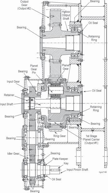
Hoist Gearcase Section View
HOIST DRUM ASSEMBLY
The hoist drum shaft uses a single-helical hoist gear fastened to a large-diameter drum with the hoist spider and rotates on double-row, tapered roller bearings.
Removal of the hoist drum shaft will require lowering and supporting the boom. To remove the hoist drum shaft:
1. Position the machine so that the dipper lip and front are flat on the ground.
DANGER: BEFORE PERFORMING ANY MAJOR MAINTENANCE ON THE HOIST MACHINERY, PRESS AND TAG THE MAIN POWER OFF BUTTON. Failure to comply may result in injury or death.
2. Remove the hoist ropes.
3. Remove the A-Frame ladders and platforms.
4. Remove the two machinery house fan/filter assemblies.
5. Remove the A-Frame shrouds.
6. Remove the center front roof panel, the 6 center roof panels and the 3 left roof panels over the left deck extension. Save all indicated items for re-use.
NOTE: To remove the center roof panel, cut the welds between the channels on the front wall panels and the center roof panel ~ both sides. The rubber sheets can remain attached to the roof panel. All front wall panels can remain in place, however the upper left and upper center wall panels can be removed, with their hardware, and saved for later reuse.
7. Remove 4 center roof cross-beams, 2 left roof cross-beams and 4 center roof fore/aft truss beams.
8. Using the crowd machinery (or a separate crane) support the weight of the boom to unload the A-Frame and main suspension strands.
9. Remove the upper A-Frame pins from the rear A-Frame legs. (Will require a cherry picker.)
10. Rotate the rear A-Frame legs back toward the rear of the machine and secure to the control room roof.
11. Using the crowd machinery (or a separate crane) lower the boom until the front A-Frame legs are pulled forward so that they are at an 80o to 85o angle to the top of the revolving frame. Set the crowd brake and block the boom in position. Install a safety cable to prevent the front AFrame from being inadvertently over center.
12. Remove the drain lines from the bearing housings. Disconnect and remove the lube lines from the hoist bearing housings and the gear guard.
13. Disconnect the hoist limit switch wiring. Remove the hoist limit switch assembly from the drum shaft.
14. Remove both the front and rear sections of the upper hoist gear guard. Each guard section weighs approx. 1,110 Lbs.
15. Use a crane to support the hoist drum shaft assembly. approx. 70,000 Lbs.
16. Remove the 3 outer 1 inch capscrews from the retainers of each of the 4 pins that attach the bearing housings to the hoist pedestals. To remove each pin, attach a suitable puller to the 3 tapped holes of the retainer and pull toward the outside of the pedestal. Note that each pin assembly weighs approx. 240 Lbs.
17. The drum assembly can now be lifted from the machine.
Installation is the reverse procedure.
HOIST GEAR REPLACEMENT
The hoist gear can be reversed on the hoist spider to provide more useful life. To reverse or replace the hoist gear, the hoist drum shaft must be removed from the machine. Remove the drum assembly using the above procedure.
1. Once removed, support the hoist drum assembly on cribbing in a vertical position, with the gear end down and the cribbing supporting the hoist gear only. Insure that the bearing housing on the gear end of the shaft or the stub shaft is not resting on the ground. This may require cribbing approx. 30 inches in height.
2. If replacing the hoist gear with a new one, insure that the new gear is resting flat on cribbing just as the old one (approx. 30 inches above the ground). If reversing the existing gear, provide suitable cribbing (approx. 30 inches in height) to rest the hoist drum and spider assembly while turning the hoist gear.
3. Support the old drum and spider assembly with a crane. Do not attach the crane support to the hoist gear.
4. Remove the 36 - 1.75 inch body-fit bolts that fasten the hoist gear to the spider.
5. Lift the drum and spider assembly away from the hoist gear.
6. Place the drum and spider assembly onto the new hoist gear (resting on cribbing).
NOTE: If reversing the existing hoist gear, set the drum and spider assembly on cribbing, turn over the existing gear with an additional crane, then set the drum and spider assembly on the gear. The hoist gear weighs approx. 12,000 Lbs.
7. Install the 36 body-fit bolts and tighten.
8. The drum shaft can now be reinstalled in the machine using the above procedure.
BEARING REPLACEMENT
To remove or replace the hoist drum shaft bearings, it is best to remove the drum shaft assembly from the machine. Use the above procedure, then proceed as follows:
1. Insure that the drum shaft assembly is resting horizontally on cribbing.
2. Remove the 8 - 1 inch rod assemblies that fasten each of the outer retainers to the bearing housings.
3. Mark then remove each outer retainer. Each retainer weighs approx. 230 Lbs.
NOTE: These parts are not interchangeable. Inspect the O-Ring on the inside of each retainer. Replace if required.
4. Pull the bearing housings (3,000 Lbs. each) from the bearings.
5. Remove the 6 - 1.5 inch capscrews that fasten each drum shaft end plate to the shaft.
6. Mark then remove each end plate (approx. 170 Lbs. each). Tag and save the shim packs for later reuse.
7. Use a bearing puller to pull each bearing from the shaft. Each bearing weighs approx. 420 Lbs.
8. Inspect the bearings, the spacer and seal remaining on the shaft ends, and the O-Ring on each seal. Repair or replace any parts as needed.
Reassembly is the reverse of disassembly.
NOTE: The bearings are assembled with an interference fit. Preheat the bearings in an oil bath to ease assembly.
HOIST OIL COOLER
The Hoist Gearcase temperature is maintained by recirculating lubricating oil through a gearcase oil cooler.
For information on the hoist oil cooler, refer to HOIST MACHINERY LUBRICATION in Section 3 LUBRICATION of this manual.
HOIST MOUNTING BOLTS
Use the following view to identify the correct installation of the mounting bolts for the hoist machinery.
For tightening the torque nuts, refer to TORQUE NUT INSTALLATION in Section 9 - Engineering Data in this manual.
HOIST LIMIT SWITCH
The hoist limit switch is used to prevent the padlocks on the dipper from being pulled into the boom point sheaves. The switch electrically cuts the reference signal. It is mechanically connected to the hoist drum shaft. It is composed of a gear reducer, an input shaft connected to the hoist stub shaft and an optical encoder. Setting the hoist limit switch is a function of the Operator’s Display in the operator’s cab. The procedure is detailed in Section 2 of this manual.
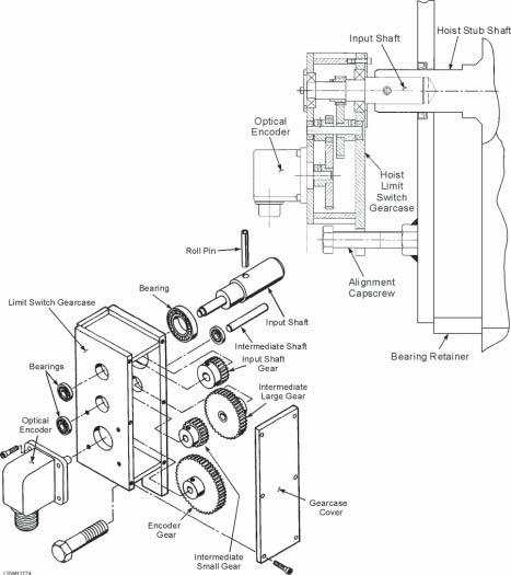
CROWD MACHINERY
The Crowd Machinery is located on the deck at the front of the machine, forward of the center of rotation. This machinery consists of the crowd drum assembly for take-up of the crowd and retract ropes, a gearcase, motor and brake.
Weekly, check both the crowd gearcases for lubrication leaks at all cover and case junctions and at the bearing retainers. Replace seals or rings if lubrication leaks are excessive. Replace sealant as required.
Weekly, check the electrical connection of the crowd motor and blower motor for tightness. Tighten the connection hardware if necessary.
Crowd Gearcase
Every six months remove the inspection covers of the gearcases and inspect the gears and pinions for pitting, abrasion, scratching, galling, spalling and other abnormal tooth wear.
Check the crowd machinery attachment pins for movement under load. Tight attachment pins minimizes wear on the pins and pin holes. Check every 100 hours.
Weekly, remove the pipe plugs in the first reduction gearcase and the second reduction gearcase and check the lubricant level. The first reduction gearcase lubricant level plug is located at the rear of the gearcase cover, to the rear of the first reduction pinion.
The second reduction lubricant level plug is located on the inboard side of the second reduction portion of the gearcase. Maintain the lubricant level at the bottom of the pipe plug opening. When lubricant sample tests prove it necessary, drain the gearcase immediately after operation, flush out the gearcase and refill with the recommended lubricant. Refer to Section 3 for the correct lubricant.
CROWD GEARCASE DISASSEMBLY
Repair of the crowd reduction gears is basically a matter of component replacement. Use the following procedures to disassemble the crowd machinery whether the crowd is on the machine or separated from the revolving frame.
NOTE: Removal of the appropriate roof panel is necessary to facilitate this procedure.
1. Remove the crowd ropes and retract ropes from the crowd drum. Refer to the instructions in the FRONT END EQUIPMENT in this manual.
2. Disconnect any lubrication lines attached to the crowd gearcases and covers. Drain the lubricant from the gearcase.
3. Disconnect the electrical leads to the crowd motor and the blower motor. Identify the leads to ensure correct installation.
DANGER: BEFORE ATTEMPTING TO DISCONNECT ANY POWER LEADS, PRESS THE MAIN POWER OFF BUTTON AND TAG IT TO AVOID INADVERTENT ENERGIZING OF THE ELECTRICAL CIRCUIT. Electrocution may lead to serious injury or death if appropriate safety measures are not followed. Electrical connections should only be handled by trained electrical personnel.
DANGER: STORED ENERGY! Gearing or drum must be blocked prior to removal of components in order to prevent unwanted movement. Failure to comply could result in death, severe personal injury, or damage to the machine.
4. Remove the motor coupling guard and separate the coupling.
5. Remove the motor shaft outboard end cover and the inboard bearing retainer. Remove the two first intermediate shaft end covers. Remove the second intermediate shaft end cover and the inboard bearing retainer. Remove the bolts that secure the second intermediate shaft left side bearing cover and inner retainer.
Crowd Motor Pinion ~Exploded View
6. Attach a crane to the gearcase cover and remove the bolts securing the cover to the gearcase. Remove the bearing cap rods, nuts and washers.
NOTE: When removing torque nuts, refer to the proper removal procedure in Section 9 Engineering Data
7. Lift and remove the cover from the gearcase. Remove the cover seal from the gearcase.
8. Attach a crane to the motor shaft and lift the shaft assembly from the gearcase. Remove the first and second intermediate shafts in the same manner.
Crowd 1st Reduction ~Exploded View
9. Dismantle the shafts as required.
a. For any shafts that are dismantled, inspect the bearings for pitting, scoring and other defects. Replace damaged bearings.
b. Check the oil seals for cuts, abrasions and other damage to the sealing surface. Replace as necessary.
c. Install new O-Rings and gaskets where required.
d. Some bearings and spacers are interference fit and must be preheated in an oil bath prior to installation on the shafts.
Crowd 2nd Reduction ~Exploded View
CROWD GEARCASE ASSEMBLY
To reassemble the crowd gearcase:
1. Install the shafts in the gearcase, using the crane to lift the shaft units.
2. Be sure the flanges of the gearcase and gearcase cover are clean. Install the seal in the groove in the gearcase. Apply a continuous bead of Loctite #515 to the gearcase flange halfway between the bolt pattern and the inside of the flange. Install the gearcase cover securing it with the necessary hardware.
3. Preload the second intermediate bearing cap against rear hook of frame with a 1-1/2" by 4" GR5 capscrew. Apply LocTite and tighten to 1,700 Ft.Lbs.
4. Install the rods and their associated hardware into the bearing caps and hand tighten.
NOTE: The bearing caps and rods are assembled with torque nuts. Refer to Section 9 ~ ENGINEERING DATA for tightening instruction.
5. Tighten the torque nuts on the rods using the proper procedure.
6. Install the retainer hardware. Install and secure the shaft end covers. Be careful not to pinch the O-Rings.
7. Attach the lubrication lines and lubricate the bearings. Fill the gearcases with oil to level with the bottom of the oil filler opening. Attach the electrical leads to the motor and the blower motor.
8. Install the crowd and retract ropes on the drum. Refer to FRONT END EQUIPMENT in this manual.
CROWD MOTOR
Inspection, lubrication and maintenance instructions for the crowd motor are described in the motor manufacturer’s manual. If removal of the crowd motor is necessary, follow the instructions below.
NOTE. Removal of the appropriate roof panel is necessary to facilitate this procedure.
Crowd the dipper outward and place the dipper on the ground.
DANGER: BEFORE ATTEMPTING TO DISCONNECT ANY POWER LEADS, PRESS THE MAIN POWER OFF BUTTON AND TAG IT TO AVOID INADVERTENT ENERGIZING OF THE ELECTRICAL CIRCUIT. Electrocution may lead to serious injury or death if appropriate safety measures are not followed. Electrical connections should only be handled by trained electrical personnel.
1. Disconnect and identify the electrical leads to the crowd blower motor and the crowd motor.
2. Remove the blower motor and duct as a unit from the crowd motor.
3. Remove the brake from the motor. Refer to Section 6 ~ BRAKES AND COUPLINGS.
DANGER: STORED ENERGY! Gearing or drum must be blocked prior to removal of components in order to prevent unwanted movement. Failure to comply could result in death, severe personal injury, or damage to the machine.
4. Remove the motor coupling guard and separate the coupling.
5. For repair of the original motor, remove the two chocks and wedges located on the side of the motor towards the boom.
6. For replacement of the original motor or motor pinion, remove the four chocks and wedges located on both the front and rear side. Also remove the two chocks at the brake end of the motor.
7. Remove the bolts securing the crowd motor to the crowd machinery frame. Use a crane to lift the motor from the frame. The weight of the crowd motor is approx. 4,000 Lbs.
8. For reinstallation of the original motor and pinion, position the motor against the two in-place chocks and wedges. Reinstall the two chocks and wedges on the boom side of the motor. Re check coupling alignment.
9. For replacement of the original motor with a new motor refer to Section 6 ~ BRAKES AND COUPLINGS. Align the motor coupling per the instructions in Section 6. Install the four chocks and wedges on both sides of the motor.
CROWD GEAR AND DRUM
Inspect the drum gear-to-drum mounting hardware for loose or missing nuts and bolts. These bolts and nuts were tightened at the factory using Turn-of-the-Nut torque method. Loose bolts and nuts should not be retightened but replaced with new bolts and nuts. Tighten the new bolts and nuts using the Turn-of-the-Nut method per Section 9 ~ ENGINEERING DATA.
Check the drum for cracks. Check the drum grooves for rough edges and other defects which would damage the crowd and retract ropes. Check the retract rope for any damage. Inspect the drum gear teeth for pitting, abrasions, spalling, galling and other damage.
CROWD DRUM REMOVAL
If repair of the crowd drum is needed:
1. Remove the crowd ropes and retract ropes from the drum. Refer to the FRONT END
EQUIPMENT in this manual.
2. Remove the gear guard from the drum gear.
3. Disconnect the lubrication lines at the shaft end covers. Remove the end covers.
4. Remove the bolted-on crowd frame lower-front cross tie.
5. Attach a crane to the drum and apply enough force to support the weight of the drum. Support the bearing caps separately.
6. Loosen the torque nuts on the bearing caps. Refer to the procedures in Section 9 - ENGINEERING DATA. Remove the preload screw from each bearing cap.
7. Remove the torque nuts and washers securing the bearing caps then carefully remove the bearing caps. The drum can then be lowered to the ground.
NOTE: The bearing cap rods are threaded into the bearing housing supports. These can remain in place.
8. Cut the lock wire and remove the retainer bolts from each end of the shaft. Remove the bearing retainers. Remove the shim pack, bearings, bearing spacer and labyrinth seals and wire together for future use.
7. If necessary, remove the hardware securing the drum gear to the drum and remove the gear. Consult the Bucyrus Service Department for repair procedures for the drum and gear.
8. Inspect the bearings for pitting, scoring, scratches and other defects. Replace defective bearings.
To reassemble the crowd drum:
1. If removed, reinstall the drum gear using new bolts and nuts.
2. Tighten the nuts to 1120 Ft.Lbs. (lubed threads, 100% proof load) or tighten the nuts to 224 Ft.Lbs. followed by 1/3 turn of the nut (dry threads).
3. Let the joint set for 24 hours then loosen and retighten. When retightening use LocTite #277 on nuts.
4. The bearings and spacers are interference fit and must be preheated in an oil bath prior to installation.
5. Attach a crane to the drum unit and position it in the frame.
6. Install the bearing caps. Preload the bearing caps against the front hook using 3/4" x 7-1/2" GR8 bolts and lockwashers. Lubricate threads and tighten to 385 Ft.Lbs.
7. Secure the bearing caps in place with special torque nuts. Refer to the proper torque nut tightening procedures in Section 9 - ENGINEERING DATA.
MACHINERY HOUSE
The machinery house has separate structural members consisting of front and rear main truss and interconnecting beams. These form the permanent house structure.
Roof panels are individually fastened to the interconnecting beams. Any panel can be removed separately to provide access to a machinery house unit. All roof panels are secured with hold down bolts on retainer bands. Vinyl tape weather stripping is installed between the retainer band and roof panel.
Shroud covers around the A-frame legs have vinyl tape between the leg and shroud. Shroud support joints are sealed with rubber cement or silicone caulking.
All mating surfaces of the machinery house wall panels are sealed with rubber cement or silicone caulking to ensure weather tight seal.
Frequently inspect all house panels and structural members for cracking. Include a close examination of all roof structures. Examine all struts, beams and braces used to reinforce the machinery house.
Always restore defective structural members to their original state by repair welding.
Periodically observe the hinges and closure mechanisms on all doors and windows to ensure they will remain closed during machine operation. Verify the sealing of the leg closures of the A-frame. Tighten all loose bolts and replace all missing hardware. The absence or looseness of these fasteners can result in excessive vibration and wear of house components. Individually, these faults can be considered minor, but taken collectively, they represent a major exposure of the electrical and mechanical elements of the house to dust and water.
Check the condition of the house paint. Paint is not impervious to deterioration. A well-painted machine is less susceptible to rust, corrosion and progressive failure.
Be sure the pressurization system is functioning properly to keep the house well-ventilated at a pressure higher than atmospheric pressure.
WALKWAYS, STAIRWAYS AND HANDRAILS
Each day inspect all walkways, platforms, stairways and handrails on the machine. Maintenance personnel should do the inspecting. Should a structural member become damaged, repair or replacement may be necessary. Replace nuts and bolts where required or repair weld to restructure individual access members such as steps and railings.
Eliminate accumulations of wiping rags, oil and grease, dust and dirt and mislaid maintenance tools. They can create a safety hazard. Keep new and used wiping rags in barrel containers rather than draped or tied to railings. Clean off oil and grease in the primary walking and working areas to prevent workers from slipping. Maintain a tool bench and rack for the storage of all tools used in the machine upkeep. Do not let tools lie scattered upon walkways and stairways.
BOARDING STAIRS
A set of boarding stairs is attached to the machinery house platform - either on the left side of the machine, the right side or both. When lowered, the stairs allow entrance to the machinery house from ground level. To activate the stairs, a chord attached to a lever arm is reachable from the ground. An additional lever is available at the top of the stairs. These stairs must be in their raised and latched position to enable the operator’s controls.
DANGER: STORED ENERGY! System may be under hydraulic pressure which can cause severe personal injury or death. Shut down pump and relieve system of all pressure before removing components.
The boarding stairs pivot about a pivot shaft attached to the boarding platform. A set of counterweights offsets the weight of the stairs. A self-contained hydraulic system, with an accumulator and cylinder, operates the stairs.
A bumper assembly attached to the latch assembly on the right machinery house wall stops the stairs when raised to the upper position. Another bumper is attached to the counterweights to prevent the stairs from lowering too far. Insure that all bumpers are in place and have not deteriorated. Both actuating levers are attached to a set of wire ropes that are in turn connected through sheaves to the latch assembly on the right wall of the machinery house. Generally very little maintenance is required for the stairs. However, insure that the flanged bearings on the pivot shaft are lubricated and also that the limit switches in the lever assembly and beneath the platform are in place and in good working order. The tension in the wire ropes should be adjusted so that approx. 15-25 lbs. of force on either lever will operate the stairs. To modify this tension, adjust the springs in the latch assembly by loosening or tightening the spring U-bolts.
FRONT END EQUIPMENT
BOOM ASSEMBLY
Maintenance of the front end equipment requires at minimum a weekly visual check for cracks or other damage to the boom structure. It will include checking the ladders and the boom point platform. Also, check for signs of wear and cracks on the sheaves. Replace, if necessary. There should always be a sign of fresh grease on both sheave bearing areas. Visually check sheave bearing retainer bolts. Inspect the boom foot lugs for any signs of cracking. Also check to see that the boom foot pins are being properly lubricated. Unusual problems should be referred to the Bucyrus International Service Department for solutions.
DANGER: STORED ENERGY! Removal of bolts and pins requires the attached items to have proper support to release the load. Failure to comply could result in death, severe personal injury, or damage to the machine.
BOOM REPAIR
Repair of the boom is normally limited to very minimal additional damage sustained following the failure of an attached component. If any structural damage is found on the boom assembly contact Bucyrus International’s Service Department immediately.
DANGER: DUE TO THE HIGH LOAD CARRYING POSTURE OF THE BOOM ASSEMBLY, ANY QUESTIONABLE DAMAGE ON THE BOOM MAY SERIOUSLY ENDANGER HUMAN LIFE AND MUST BE INVESTIGATED BY QUALIFIED PERSONNEL BEFORE CONTINUED SERVICE CAN BE UNDERTAKEN.
BOOM LIMIT SWITCH INSTALLATION
To adjust the Boom Limit Switch: 1. Insure that the machine is level, the dipper is resting on the ground, and that the hoist ropes are slack. The crowd must be allowed to unload all forces against the rack.
NOTE: Refer to Section - A on the following page. 2. Loosen the .38 inch capscrews that fasten the proximity switch bracket to the mounting angle. The slotted holes in both pieces allow for bothhorizontal and vertical adjustment.
3. Adjust the position of the proximity switch to the dimensions shown in Section A on the following page.
Boom Inductive ProximitySwitch
Overall sensitivity can be further adjusted from this initial position to suit conditions.
BOOM POINT SHEAVES
This machine uses 2 Boom Point Sheave assemblies to redirect the hoist ropes from the dipper padlock to the hoist drum. Check the boom point sheaves monthly for unusual wear. Check that the sheave bearings are receiving proper lubrication and that the lube lines are not damaged or crimped. For detailed sheave inspection procedure refer to the topic near the end of this manual.
BOOM POINT SHEAVE REMOVAL AND DISASSEMBLY
Use the following procedures to remove ONE Boom Point Sheave assembly:
1. Position the machine in a clear and level area.
2. It is not necessary to lower the boom when removing the boom point sheaves. However, lift the hoist ropes, with a suitable crane, and set them at the center of the boom away from the sheave assemblies.
CAUTION: THE HOIST ROPES MUST BE SECURED TO THE BOOM FOR SAFETY UNTIL THE REPAIR IS COMPLETED. USE BLOCKING BETWEEN THE ROPES AND THE BOOM STRUCTURE TO PREVENT DAMAGE TO THE ROPES.
CAUTION: ADEQUATE PRECAUTIONS MUST BE TAKEN TO ENSURE THE SAFETY OF PERSONNEL WHEN EQUIPMENT IS REMOVED AND REPLACED. USE EXTREME CAUTION AND PROPER SAFETY DEVICES WHEN WORKING AT THE BOOM POINT.
3. Disconnect and plug the lubrication lines to the sheave pins.
4. Use a suitable crane and provide just enough lift to the boom point sheave to be removed to carry its weight. The approximate weight is 7,000 Lbs. DO NOT APPLY TOO MUCH FORCE
WITH THE LIFTING DEVICE.
5. Remove the sheave clamp collar from each end of the boom point shaft.
6. Ensure that the sheave assembly is supported with a sufficient sling or chain and loosen the four 1.5 inch capscrews that retain the bearing caps on the shaft to be removed.
7. With the shaft assembly secured, remove the capscrews and bearing caps.
8. Lift the sheave assembly away from the boom point and set on the ground.
NOTE: When lifting the sheave assembly, locate the key at the bottom of the outboard end of the shaft and retain for reinstallation.
CAUTION: THE SHAFT KEY MAY FALL WHEN THE SHAFT IS LIFTED!
To disassemble the boom point sheave:
1. Remove the spacer from the shaft.
2. Remove the bearing retainer, bearing clamp and associated hardware from both sides of the sheave.
3. Use caution and remove the O-Ring and seal from each retainer.
4. Remove the bearing clamp from each side of the sheave and also the O-Ring from each bearing clamp.
5. Remove the shims from the inboard side of the sheave.
6. Remove the sheave and bearing from the sleeve. Separate the bearing from the sheave.
7. Remove the sleeve from the shaft.
8. Check then repair all damaged or worn parts.
BOOM POINT SHEAVE REASSEMBLY AND INSTALLATION
1. Apply a thin coat of Molycote G to the shaft. Install the sleeve onto the shaft. Install the bearing and sheave onto the sleeve.
Use the following steps to install the shims:
a. Install the inside and outside bearing clamps, Ensure they are tight against the boom point sheave sleeve.
b. Use a depth mic through the 4 holes to measure the depth of the outside bearing clamp. Average this dimension.
c. Remove the outside bearing clamp and measure the thickness at the same 4 points. Average this dimension.
d. Subtract the averaged second outside dimension from the averaged first hole dimension.
e. Subtract .002 - .005” from this dimension and use this as the new shim thickness.
f. Install the shims. Assemble the O-Ring to each bearing clamp then install the bearing clamps.
g. Tighten the .75 inch socket head capscrews in a criss-cross pattern to snug tight. (Appros. 53 Ft.Lbs.)
h. Continue to tighten the capscrews 1/3 of the required torque value at a time, until the proper torque is achieved. Refer to Section 9 - ENGINEERIN DATA in this manual for the proper torque value.
3. Assemble the seal and O-Ring to each bearing retainer then install the bearing retainers. Tighten the .75 inch capscrews and lockwire in place.
4. Slide the spacer onto the end of the shaft opposite the keyway.
To reinstall the boom point sheave assembly:
1. Insert the shaft key into the proper slot in the boom point structure.
2. Using a suitable crane, lift the sheave assembly into place at the boom point.
NOTE: The sheave assembly must be oriented with the spacer near the end of the shaft toward the center of the boom, and also the key slot on the shaft must be at the bottom and toward the outside of the boom. Ensure that the ends of the shaft in the bearing cap area are coated with Molycote G.
3. With the shaft in place, attach the bearing caps and capscrews.
4. Tighten the 1.5 inch capscrews to 1460 Ft.Lbs.
5. Slide the shaft toward the center of the boom as far as possible. Attach the clamp collar on that end and tighten its capscrews.
6. Slide the shaft as far as possible toward the outside of the boom. Attach the clamp collar on that end and tighten its capscrews.
7. Reconnect all lube lines.
8. Using a crane lift and set the hoist ropes back onto the sheaves. DO NOT CROSS THE
HOIST ROPES. If required, refer to the proper reeving instructions in this section of the manual.
BOOM BUMPER
Regularly check the condition of the boom bumper and make repairs as required. Inspections should be conducted at minimum of once per operating shift. Additional inspections may be required. Operator’s style will affect bumper life. Repair of the boom bumpers consists of replacing common hardware and cushion material.
DANGER: STORED ENERGY! Removal of bolts and pins requires that the attached items be properly supported to release their load. Failure to comply could result in death, severe personal injury, or damage to the machine.
SADDLE BLOCK
The saddle block should be inspected daily for signs of excessive wear. Make certain that it is being adequately lubricated and that the injectors are functioning properly. Also check the condition of the shipper shaft sheaves for signs of unusual wear. The lubrication lines which run up the boom should be checked for any signs of damage or crimping which could impede the flow of lubricant to the saddle block.
SADDLE BLOCK REPAIR
Saddle Block Bushing Arrangement
The saddle block liners should be replaced when the 0.50 inch chamfer has been worn off the inner bushings, or when the measured distance from one side of the handle to the lining is 0.12 inch or less - with the handle pushed to the same side of the liner. Measure the liners at 4 equally-spaced points about its circumference. It may be possible to remove the liner capscrews and rotate the liner for additional wear. Replace the liners as follows: 1. Remove the dipper handle per the procedures in Dipper Handle Removal. 2. Secure the rear liner with a crane and remove the liner mounting bolts. Remove the liner from the saddle block. NOTE: The liner was installed with LocTite. It may be necessary to heat the saddle block or to cut the liner in order to remove it. Discard after removal. 3. When installing new rear liners, uniformly coat the mating surfaces of liner O.D. and saddle block I.D. with LocTite (R) 680 immediately before installation. Use Loctite 227 on the liner bolts.
4. Replace the front liners using the same procedures as above.
SADDLE BLOCK REMOVAL
For any work to be done on the saddle block other than replacement of liners, the saddle block must be removed from the machine. Remove the saddle block as follows:
1. Remove the crowd and retract ropes as described under Crowd & Retract Rope Removal.
2. Remove the dipper handle as described under Dipper Handle Removal.
3. Two cranes are required to remove the saddle block. One crane is used to support and remove the saddle block. The other crane is used to remove the shipper shaft.
4. Separate and plug the lube lines to the saddle block.
5. With a crane supporting the saddle block, remove the shipper shaft clamp collars and slide the shipper shaft to either side to remove it from the saddle block and boom. Lower the saddle block to the ground.
6. Check the shipper shaft bushings in the boom and replace if required. Consult Bucyrus Service Department prior to starting repair.
Saddle Block Sheave
7. Inspect and replace any worn sheave bearings and seals or saddle block bushings.
Bearing retainer shimming instructions:
a. Install the spacer and the bearing on the saddle block. Install the seals and the seal retainers. Press the bearing tight against the spacer.
NOTE: Do not install the saddle block retainer.
b. Install the bearing retainer. Tighten just until snug, the socket head cap screws that hold the bearing retainer in place.
c. Keeping the bearing tight against the spacer, measure the depth along the outer edge of the bearing retainer using the depth micrometer as shown. Remove the bearing retainer and measure the retainer thickness.
d. Subtract the measured retainer thickness from the measured depth to calculate the gap and assemble the shim with the thickness equal to the gap thickness -0.002 to 0.005.
e. Re-install the bearing retainer and snug-tighten the cap screws. All cap screws require retaining compound 82 833 859. Tighten in a sequence 180° apart in 3 steps adding 1/ 3 torque value each time.
NOTE: All cap screws should be tightened to 146 Ft. Lbs.
8. Reinstall the saddle block in the boom. Reconnect the lube lines. Reinstall the dipper handle. Reeve the crowd and retract ropes on to the machine.
DIPPER HANDLE
The dipper handle assembly should be checked regularly for bending or any structural cracks. If any cracks or bending is noticed, remove the handle and repair as required For instructions and/or assistance, please refer to Bucyrus International’s Service Department.
Check the handle for proper lubrication in the area that passes through the saddle block. Insure that the automatic lubrication system is working properly.
Check the condition of the retract rope take-up mechanism and the crowd rope screw rod adjustment mechanism. Insure that all components are present and all hardware is tight.
DIPPER HANDLE REMOVAL
1. Crowd the handle out until the saddle block is a slight distance from the crowd cushion. (This is to prevent undo tension on the worm gear housing capscrews.) Lower the dipper to the ground, resting it with the heel on the ground. Set all machine brakes, but do not lock out the power.
2. Remove the crowd and retract ropes. Refer to the proper instructions in the rope removal and replacement section of this manual.
3. Support the crowd screw half-sheave assembly with a crane, both at the half-sheave and at the take-up guide. (Weight is approx. 10,500 Lbs.) Be sure not to damage the bellows. Note the location of the lifting lug on the top of the take-up guide housing.
4. Remove the 28 - .75 inch capscrews, on the half-sheave end of the handle, that attach the worm gear housing and take-up guide to the handle. Do not remove the 7 capscrews toward the inside of the worm gear housing, nor the 12 nuts and capscrews holding the cushion in place, at this time.
NOTE: The 7 capscrews toward the inside of the worm gear housing attach the housing to the take-up guide. These screws must remain in place when removing the crowd rope take-up mechanism as a unit.
5. The crowd rope adjusting mechanism consists of the crowd half-sheave, screw rod, bellows, worm gear housing and crowd cushion. With the capscrews mentioned above removed, carefully slide the take-up mechanism out of the handle then lift it away from the handle and rest it on cribbing.
6. Secure a crane to the dipper handle, between the saddle block and the dipper. Insure that the crane will support the free end of the handle. Apply additional rigging to prevent the crane cable from sliding away from the dipper end of the handle. Support the saddle block to prevent it from rotating in either direction once the handle has been removed.
CAUTION: THE SADDLE BLOCK MAY ROTATE SUDDENLY ONCE THE HANDLE IS REMOVED. Be sure the saddle block is supported to prevent its rotation once the handle has been removed.
CAUTION: The rigging from the crane must be securely fastened with additional rigging to prevent the crane cable from sliding away from the dipper end of the handle, and also to support the free end of the handle once it is removed from the saddle block.
7. While supporting the dipper handle with a crane, SLOWLY propel the machine in a straight line to the rear. The dipper handle will slide from the saddle block.
CAUTION: THE DIPPER HANDLE WILL FALL ONCE REMOVED FROM THE SADDLE BLOCK IF IT IS NOT FULLY SUPPORTED.
8. Set the free end of the dipper handle on blocking and perform the required maintenance. While the handle is on the ground, the crowd half-sheave (previously removed) and retract take-up mechanism should be inspected and repaired if required.
Dipper handle installation is the reverse of removal. Note the following: • Carefully align the free end of the dipper handle and the saddle block before propelling the machine forward.
• The crowd rope screw adjusting mechanism should be completely pre-assembled AND THOROUGHLY LUBRICATED before installing into the end of the dipper handle. Refer to the note in CROWD ROPE TAKE-UP MECHANISM ASSEMBLY.
• BE SURE THAT THE WORM GEAR HOUSING AND CROWD HALF-SHEAVE ARE PERFECTLY LEVEL WITH THE DIPPER-TO-HANDLE PINS AND ALSO WITH THE RETRACT ROPE SPREADER AND TAKE-UP MECHANISM.
• Install the crowd and retract ropes using the proper procedures in this section of the manual.
CROWD ROPE TAKE-UP MECHANISM
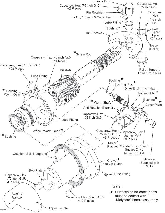
CROWD ROPE TAKE-UP MECHANISM DISASSEMBLY
With the take-up mechanism off the machine, set it in a vertical position with the take-up guide up and the clevis end of the screw rod down, then proceed as follows to disassemble it:
1. Remove the 12 - .5 inch capscrews that fasten the crowd cushion to the forward side of the take-up guide. Then remove the crowd cushion.
2. Remove the crowd rope roller supports from the half-sheave.
3. Remove the sheave pin lock plate and remove the pin. Slide the half-sheave out from the screw rod clevis.
4. Insert an 8.00” long, 0.50” bolt or threaded rod into the end of the worm shaft opposite the drive end.
5. Remove the anti-rotation bracket from the worm shaft. Remove the worm shaft cover at the bottom of the worm gear housing. Remove the thrustwasher bushing from the shaft.
6. Turn the worm shaft counter-clockwise to remove it from the worm gear housing. Remove the remaining thrust washer bushing.
7. Remove the stop plate from the square end of the screw rod.
8. Remove the 7 - .75 inch capscrews that attach the worm gear bushing to the take-up guide. Remove the take-up guide..
9. Remove the larger bushing from inside the bore of the take-up guide.
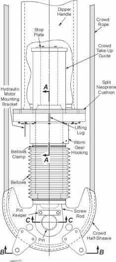
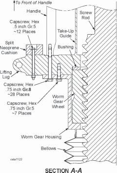
10. Turn the worm gear wheel to remove it from the screw rod.
11. Loosen the clamps on the bellows. Remove the worm gear housing from the bellows and screw rod.
12. Carefully remove the bellows from the screw rod.
13. Remove the smaller bushings from inside the worm gear housing and the worm shaft cover.
Inspect all parts for wear or cracking. Check for evidence of the proper amount of lubricant on all moving parts. Repair or replace any defective parts as required.
CROWD ROPE TAKE-UP MECHANISM ASSEMBLY
NOTE: Before beginning to assemble the take-up mechanism, fully cover all rubbing and contact surfaces with Molykote. DURING ASSEMBLY LIBERALLY COAT THE SAME SURFACES WITH TEFLON LUBE BUCYRUS PART NIUMBER 62038320.
Assemble the take-up mechanism in the following order:
1. Position the screw rod so it is vertical and with its square end on top.
2. Slide the bellows onto the square end of the screw rod, down to the clevis end of the rod.
3. Shrink the worm shaft bushing and install it into the right-hand worm shaft bore at the bottom of the housing.
4. Shrink the opposite worm shaft bushing into the worm shaft cover.
5. Slide the worm gear housing onto the screw rod until it mates with the bellows.
6. Slide the worm gear wheel onto the screw rod and spin it onto the threaded portion of the screw rod.
7. Slide the worm gear bushing onto the screw rod.
8. Slide the crowd take-up guide onto the screw rod. Note the orientation of the lifting lug on the take-up guide.
9. Position the worm gear housing so that the worm shaft housing is opposite to the lifting lug on the take-up guide. Check that the bolt holes on the housing and crowd take-up guide are aligned for the capscrews.
10. Bolt the screw rod stop plate to the end of the screw rod using the 4 - .75 inch capscrews. Tighten the clamps on the bellows.
11. Install an 8.00” long, 0.50” bolt or threaded rod into the end of the worm shaft, opposite the drive end, for assembly purposes.
12. Slide one thrust washer bushing onto the end of the worm shaft, opposite the drive end.
13. Insert the worm shaft into its housing. Spin the worm shaft clockwise until it is fully inserted.
14. Install the remaining thrust washer bushing on the drive end of the worm shaft. Slide the cover onto the worm shaft and bolt it to the housing using 6 - .38 inch capscrews. Assemble the anti-rotation bracket. Remove the bolt or threaded rod from the end of the worm shaft that was used for assembly.
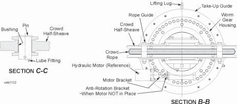
15. Insert the pin bushing into the crowd half-sheave and assemble the half-sheave to the screw rod with the half-sheave pin. Attach the pin locking plate and 2 - 1 inch capscrews.
16. Install the roller support plates to the half-sheave. Leave the rollers off until the crowd rope has been installed.
17. Pump grease into the worm shaft housing until the grease comes out from the lube relief valve. This will require about 1.5 gallons.
18. Attach the crowd cushion halves to the take-up guide.
RETRACT ROPE TAKE-UP MECHANISM
The retract rope take-up mechanism is attached to the dipper handle at the dipper end and provides the ability to remove slack from, and apply the proper tensioning to, the retract rope.
To repair the retract mechanism:
1. Lower the dipper so that the front of the dipper is flat on the ground.
2. Remove the shim guard bolts and rotate shim guard out of the way.
3. Unload retract rope using hydraulic jacks to remove shims as follows:
CAUTION: Oil within the needle valves is under high pressure. STAY CLEAR OF TAKE-UP NUT, SHIMS AND CYLINDERS WHEN OPERATING NEEDLE VALVE, AS THESE ITEMS COULD MOVE UNEXPECTEDLY AND CAUSE SERIOUS INJURY.
a. Clean and grease the sliding area on the take-up nut, support and screw. b. Make sure the right needle valves are open and the left needle valves are closed. c. Extend the cylinders by injecting hydraulic fluid into the coupler located on the left side of the dipper handle above the left needle valve.
d. Remove the desired amount of shims from the cylinder side of the take-up nut and store them on the opposite side of the nut.
CAUTION: The take-up nut must be shimmed tight, both fore and aft, using all shims originally provided with machine.
e. Slowly open the left needle valve.
CAUTION: Stay clear of the take-up nut. The weight of the rope may jerk the takeup nut when the needle valve is opened.
f. Close the right needle valve.
4. Release the pressure from the hydraulic jacks.
5. Repair or replace any damaged parts.
6. Retighten the retract rope per the procedure in RETRACT ROPE TIGHTENING later in this section of the manual.
SPREADER REPAIR
NOTE: The following procedures involve burning and rewelding the spreader. Contact Bucyrus International service department for the proper weld specifications for this item.
1. Lower the dipper to the ground.
2. Back-off the retract rope as far as possible. Refer to removal step 3 of RETRACT TAKE-UP MECHANISM.
3. Remove the retract rope retainer bolts and retainers. Lift the retract rope out of the spreader grooves.
4. Carefully burn out the weld joining the cylinder guard support to one-half of the spreader only. The cylinder guard support can remain attached to the other half of the spreader.
5. Burn off the upper and lower splice plates from one-half of the spreader. The splice plates can remain attached to the other half of the spreader.
6. Attach a crane to one side of the spreader. Remove the anchor bolt attaching that side.
7. Lift the spreader from the handle.
8. Attach a crane to the remaining side of the spreader, remove its anchor bolt and lift it from the handle.
9. Repair or replace any damaged parts.
10. Reinstall each half of the spreader and their anchor bolts, but do not tighten the anchor bolts.
11. Be sure the spreader assembly is aligned to the handle so that one side is aligned with the other side and each side is an equal distance from the handle.
12. Contact Bucyrus International service department for the proper weld specifications for the spreader.
13. Tighten the anchor bolts, then tighten the retract rope using the procedure in RETRACT
ROPE TIGHTENING later in this section of the manual.
DIPPER ASSEMBLY
The dipper should be inspected before the start of each shift. The side and front surfaces provide critical reinforcement for the dipper. Consequently, they should be checked regularly for cracks and component wear. When wear spots develop in the side and front surfaces, the metal contour can be restored by building up the affected area. Contact the Bucyrus International Service Department for a specified welding repair solution.
DANGER: THE DIPPER HANDLE WILL FALL ONCE REMOVED FROM THE SADDLE BLOCK IF IT IS NOT FULLY SUPPORTED. Removal of bolts and pins requires the attached items to have proper support to release the load. Failure to comply could result in death, severe personal injury, or damage to the machine.
NOTE: Do not apply hard-surfacing to steel side and front surfaces. This could promote the development of cracks. Where wear is excessive, mild steel plates can be welded in place and hard-surfacing applied to these additional plates with excellent results. All lubrication points should be inspected and lubricated each shift. The dipper should also be checked for missing or broken teeth or missing wedges. These items if missing or broken must be replaced before digging is started. Check the latch bar and the latch bar keeper insert, if applicable, for wear and replace if required.
Dipper Door Latch Bar and Lever
Check the latch bar and latch lever for proper adjustment. The latch bar should be adjusted so that it enters the latch keeper pocket between 3/4 and 1 inch per the following procedure.
LATCH BAR ADJUSTING PROCEDURE
1. Insure door is stable so that it will not move during adjustment procedure.
2. Use jack lever to rotate screw jack to raise latch lever and pivot bracket.
3. Remove shim retaining bar and add or remove shims as desired.
4. Install shim retaining bar.
5. Lower screw jack with jack lever until it clears latch lever pivot bracket and bracket has solid contact with shims.
6. Store jack lever in retaining hole provided.
DIPPER DOOR SNUBBERS
The dipper door snubbers provide tension on the dipper door to prevent excessive speed and movement of the dipper door during closing. Check the door snubber periodically for proper tension.
CAUTION: STORED ENERGY! The snubber pads are under compression. Care must be taken when removing the adjusting nut in order to avoid injury.
SNUBBER ADJUSTMENT
These adjustment procedures apply to the following snubber assemblies using urethane snubber pads:
E016896-01 &- 02, E017485-01 & -02, E017992-01 & -02, E019671-01 & -02, E020438-01 & -02, E020930-01 & -02, E020940-01 & -02
(Refer to the Parts Book for the proper part numbers).
CAUTION: DO NOT use these procedures for snubber assemblies that use belleville washers.
To adjust the dipper door snubbers:
1. Using a torque wrench, tighten both snubber adjusting nuts to 650 Ft. Lbs. (Approximately 30,000 Lbs. bolt tension). Both snubbers must be adjusted EQUALLY!
2. Observe the door closing during the machine dig cycles. Further tighten or loosen the adjusting nut to allow the dipper door to gently contact the dipper body.
3. Repeat the above steps as necessary to minimize dipper-to-door contact.
4. After all adjustments are complete, rotate the adjusting nut just enough to reinstall the adjusting nut cover. Record the final torque for future snubber adjustments.
5. After two full days of operation (40 hours), re-tighten snubbers to the final torque setting.
6. Periodically check snubbers and re-tighten to the final torque setting as needed (usually 2 months or more).
DIPPER PITCH BRACES
DIPPER PADLOCK
The padlock should be checked every shift to see that all pin retaining bolts are not loose or missing. All lubrication points should be lubricated every shift.
DANGER: STORED ENERGY! Removal of bolts and pins requires the attached items to have proper support to release the load. Failure to comply could result in death, severe personal injury, or damage to the machine.
Daily check excessive movement at the pin joints which indicate bushing wear. Replace worn bushings and pins. Check for cracking in the frames and links and make repairs when required.To Repair the Dipper Padlock:
1. Place the dipper on the ground. Remove enough tension from the hoist ropes to remove the weight from the dipper lug pin, but not allowing enough slack to permit the weight of the padlock to rest on the pin. 2. Remove T-bolts retaining the lug pin. Remove lug pin with suitable lifting device. 3. Using hoist ropes, lift the padlock from the dipper padlock lug and lower padlock to the ground. Remove thrust washers and dowels from the lug. 4. Remove T-bolt retaining the link pin. Strike the link pin foot with enough force to expose enough of the link pin head to secure to a suitable lifting device. Remove link pin from padlock frame. 5. Remove bushings from the link and from lower padlock frame. The bushings have an interference fit. 6. Support the padlock sleeve. Remove T-bolts retaining the padlock sheave pin. Remove sheave pin with a suitable lifting device. 7. Using a suitable lifting device, remove the padlock sheave from padlock frame. Remove the thrust washers and dowels from the sheave. 8. Remove the hoist rope from padlock frame. Remove the sheave pin bushings from padlock sheave and frame. The bushings have an interference fit. See Bushing Fits Tabulation on figure. 9. Clean and inspect all parts. Repair or replace all damaged or worn parts. 10. Reassemble in reverse of disassembly. Be sure all the dowels are flush with, or below, the surface of the thrust washers.
The upper and lower pins of the padlock appear to be identical. These items are identical in size only! The material of construction and part numbers are different. Ensure they are placed in the proper location during assembly.
DIPPER TRIP ASSEMBLY
The dipper trip can be disassembled in place on the machine or removed as a complete unit. In either case, the disassembly procedure is the same.
CAUTION: AVOID ANY METHODS WHICH ALLOW THE ROPE TO BECOME UNCONTROLLED AT ANY TIME DURING THE REEVING OPERATION. Death, serious injury, or damage to the machine will result should a rope become uncontrolled.
1. Remove the drum guard and trip rope from the drum.
2. Open the gear and pinion guard.
3. Remove the drum retainer and drum.
4. Remove the bearing retainer and spacer on the drum side. Then remove the cover and bearing retainer at the other end of this shaft.
5. Support the gear and slide the shaft from the gear and base on the drum side of the base. Remove the gear, bearings, spacers and seals.
6. Repair or replace all worn or damaged parts and reassemble in reverse order of disassembly. Lubricate the bearings.
7. If the pinion was removed from the motor, when it is reinstalled, the motor shaft should be recessed inside of the pinion 1/16 inch.
A-FRAME
Periodically inspect the A-frame for signs of cracking or other damage. This check should include the mounting lugs and pins, the ladders and platforms, the equalizer links holding the boom structural strands and the leg shrouds on the machinery house roof. Make certain there are good seals around the leg shrouds.
If any repair welding is required, contact the Bucyrus International Service Department for a specialized repair process. For any other unusual problems consult the Bucyrus International Service Department.
Carefully inspect the mounting lugs and pins for cracks or other signs of wear or deterioration. Lubricate these areas occasionally to prevent rusting. Check the leg shrouds both from the inside and on the top of the machinery house to see that a tight seal is maintained and there are no leaks. If there are any signs of leaking, reseal around the shrouds with a suitable caulking compound.
Make certain the ladders are securely mounted in good condition. Repair any cracks as soon as they are noticed.
Check the condition of the platforms to see that they are secure and safe. At the same time inspect the equalizer links and connections of the boom structural strands.
DANGER: STORED ENERGY! Removal of equalizer pins requires the attached items to have proper support to release the load. Failure to comply could result in death, severe personal injury, or damage to the machine.
Under normal circumstances the A-Frame of the machine will most likely not be removed until disassembly of the machine is required. Please contact the Bucyrus International Service Representative should any unusual circumstances arise.
AUXILIARY WINCH
The auxiliary winch is attached to the hoist ropes to raise and lower the ropes during hoist machinery maintenance and change-out of hoist ropes. The winch consists of a drum and rope mounted to an electric gear motor. The winch can be single or double arrangement. The double arrangement is shown.
The winch can be single or double arrangement. The double arrangement is shown. The winch consists of a drum and rope mounted to an electric gear motor.
HOIST ROPE SUPPORT ROLLER
The hoist rope support rollers are used to guide the hoist ropes as they leave the hoist drum and exit the machinery house.
The rollers should be inspected daily for wear. The roller bushings should be lubricated once every shift. Repair of the rope rollers will consist mainly of replacement of worn bushing and/or rollers.
BOOM SUSPENSION ROPES
Periodically inspect the outer layer of wires immediately adjacent to the sockets. If 30% of the outer strands are broken, the strand must be replaced. Lubricate the suspension rope sockets every 3 months or 1250 hours of machine operation.
DANGER: STORED ENERGY! Removal of equalizer pins requires the attached items to have proper support to release the load. Failure to comply could result in death, severe personal injury, or damage to the machine.
Additional, detailed information can be found in “Wire Rope Care and Maintenance” in Section 9 ENGINEERING DATA.
WIRE ROPES
In designing excavating machinery, careful study of the size and operating speed of all sheaves and drums is conducted to determine the proper wire rope for each application. Continual contact with many machines in the field and repeated consultation with leading rope manufacturers permits the selection of the most satisfactory rope for each machine. To maintain the machine at its highest level of efficiency, purchase new ropes which conform to Bucyrus International specifications, and thereby obtain the wire rope best suited for the particular application. Here are a few pointers relative to the proper inspection, lubrication and replacement of wire ropes on the machine.
WIRE ROPE INSPECTION
1. It is the operator’s responsibility to maintain drums and sheaves in good condition. Use ropes of proper size and construction. Examine ropes for signs of deterioration or damage in service, replace them when necessary.
2. It is customary to work the running ropes almost to destruction in order to reduce the machine operating cost and downtime for replacement. When loading trucks, hoppers and the like, which would be damaged by a falling dipper, ropes should be inspected for signs of deterioration.
3. Outer wires of the hoist ropes may be damaged or broken by falling rocks, by chafing over sharp rocks in the bank and by the presence of stones in sheave grooves. Rope life may be prolonged if broken wires are trimmed so that they do not cross over and cause additional damage to adjacent unbroken wires.
4. The operator should always observe safety precautions.
5. For more information refer to the WIRE ROPE CARE AND MAINTENANCE in Section 9 ~ ENGINEERING DATA.
CROWD ROPE TAKE-UP HYDRAULIC UNIT
DANGER: STORED ENERGY! System may be under hydraulic pressure which can cause severe personal injury or death. Shut down pump and relieve system of all pressure before removing components.
This hydraulic unit is used to apply torque to the worm shaft at the end of the dipper handle when adjusting the tension in the crowd rope. It is located on the machinery house roof, near the center of the machine just behind the operator's cab.
The hydraulic unit is a self-contained unit, including a reservoir of hydraulic fluid, a stationary pump and electric drive motor, and a removable hydraulic motor (with handles) connected to the pump through a length of hydraulic hoses. To operate the unit, withdraw the hydraulic motor from its storage on the unit and install the motor on the dipper handle. Refer to the instructions in CROWD ROPE ADJUSTMENT, in this section of the manual, for the proper procedures. Press the start pump button on the control panel then use the hand held pendant station to control the pump.
Be sure the reservoir is filled with hydraulic fluid. Check for leaks in the piping. Replace the filter cartridge when indicated.
Hydraulic Schematic ~Crowd Screw Hydraulic Unit
HOIST ROPE REEVING & REPLACEMENT
NOTE: The procedure outlined in this manual assumes that the old hoist ropes are not broken or severely frayed, that the machine is equipped with an auxiliary rope winch and that all of the tools and supplies specified are on hand. THE HOIST ROPE MUST BE KEPT UNDER COMPLETE CONTROL AT ALL TIMES.
CAUTION: AVOID ANY METHODS WHICH ALLOW THE ROPE TO BECOME UNCONTROLLED AT ANY TIME DURING THE REEVING OPERATION. Death, serious injury, or damage to the machine will result should a rope become uncontrolled.
To replace the hoist ropes:
1. The machine should be in a clear, flat area with sufficient room in front of the machine to work. All applicable safety regulations should be followed. Only personnel directly connected with replacing the ropes should be allowed on or near the machine.
DANGER: ROPE END(S) WILL FORCEFULLY UNCOIL IN RELEASE OF ENERGY WHEN SHIPPING RESTRAINTS ARE REMOVED.
DANGER: The condition of the ropes may make it necessary to modify the procedures outlined, especially if the rope is broken or severely damaged. Be sure to always follow safety precautions when burning or climbing. Always keep the ropes under complete control.
2. Lower the dipper to the ground. Position the dipper so that the padlocks are directly beneath the point sheaves. The hoist ropes will be vertical and the heel of the dipper will be on the ground.
3. Position a person in the machinery house in a position to observe the hoist drum and ropes. Slowly rotate the drum in a lowering direction until all of the rope is spooled off of the drum and the rope sockets are in the bottom rear quadrant of the hoist drum.
CAUTION: Throughout this operation drum or rope positions must be communicated to the operator. Make sure that a system of signals is worked out in advance and that the line of communication is unbroken.
NOTE: Each hoist rope is a continuous length of rope.
• The “LEAD ROPE” is the portion of rope from the hoist drum, over the outer groove of the point sheaves, and down to the back of the padlock. The socket on the hoist drum for this rope “LEADS” the socket for the “FOLLOW” rope. • The “FOLLOW ROPE” is the portion of rope from the front of the padlock, over the inner groove of the point sheaves, and back to the hoist drum.
4. Attach an auxiliary winch line to each follow rope becket. Remove the keeper that attaches the follow ropes to the hoist drum.
5. Pull the ferrules out of the becket receivers. Lower the auxiliary winch line until the hoist rope can be tied off. Tie-off the follow ropes.
6. Carefully rotate the drum 180° in the LOWER direction to unwrap the remainder of the lead ropes from the drum.
7. With the lead rope sockets in the lower rear quadrant of the drum, stop the drum.
8. Attach the auxiliary winch line to each lead rope becket. Remove the lead rope keeper. Payout the winch line until the lead rope can be tied off then tie it off.
9. Attach the follow ropes to the winch line.
10. Attach a sling to the follow rope near the front of the padlock. Attach this sling to a ground vehicle.
11. Slowly and carefully payout the auxiliary winch while pulling the hoist rope away from the front of the machine with the ground vehicle. Lower the hoist ropes until the winch line can be disconnected.
NOTE: The ground vehicle is required to pull the weight of the hoist ropes over the boom point sheaves, and also help bend the ropes through the padlock sheaves.
12. Rotate the hoist drum in the lower direction until the lead rope keeper in is the lower rear quadrant.
13. Attach a winch and lower the lead ropes in the same manner as that used for the follow ropes. When the ends of the lead ropes approach the padlocks, one rope must be removed from the winch line, the remaining lead rope lowered through the padlock, and then removed from the winch rope.
To install a new pair of hoist ropes:
1. Place the new hoist ropes approximately 10 feet in from of the dipper. If the ropes are on reels, they should be located so that the ropes unreel from the bottom of the reel.
DANGER: ROPE END(S) WILL FORCEFULLY UNCOIL WHEN SHIPPING CONSTRAINTS ARE REMOVED.
2. Be sure a winch line runs through each padlock.
3. Attach a winch line to one end of each new rope, making them the new lead ropes.
4. Hoist the winch until the lead ropes have cleared the padlock. Attach the free end of each hoist rope to the winch line that its lead end is attached to.
5. Pull both ropes over the point sheave, being careful to keep the lead rope (rear rope in padlock) on the outside groove of the point sheave.
6. Continue pulling the ropes into the machinery house. When the ends of the ropes reach a point where the follow rope can be tied off, stop pulling, detach the follow rope from the winch line and tie it off.
7. Pull the lead ropes until they are in a position to be placed in there becket resolvers. Place the lead rope ferrules in the resolvers, install the lead rope keeper and detach the winch line.
8. Slowly rotate the drum 180° in the HOIST direction so that the follow ropes can be attached.
9. Hoist the winch attached to the follow ropes until the ropes can be attached to the drum.
10. Place the follow rope ferrules in the resolvers, install the lead rope keeper and detach the winch line.
11. Slowly rotate the drum in the hoist direction until the hoist ropes are tight. Make sure the ropes stay in the proper grooves.
12. Hoist the dipper approximately 1 foot off of the ground. Check to make sure the dipper hangs straight. If not, place shims between the ferrule and the ferrule socket on either the lead or the follow ropes on the side that the dipper hangs lower. If necessary, locally manufactured shims may be placed under both ferrules.
13. Hoist and lower the dipper several times to seat the ropes. Make sure the dipper hangs straight. If not, shim as above. Reset the hoist and crowd limit switches.
Shim for Hoist Rope Socket
NOTE: The above steps are used to remove and replace 1 pair of hoist ropes. When replacing a single hoist rope, be sure to check the alignment of the dipper and shim the old rope if required to level the dipper.
CROWD ROPE REEVING & REPLACEMENT
NOTE: To use the procedure below the old crowd rope must not be broken or severely frayed, the new crowd rope should be wound on a shipping reel with one ferrule button-end in and one ferrule button-end out, and all tools and equipment specified must be on hand.
DANGER: AVOID ANY METHODS WHICH ALLOW THE ROPE TO UNWIND OR FALL UNCONTROLLED. An uncontrolled rope could cause death or serious injury.
NOTE: Should it be necessary to replace both the crowd and retract ropes, THE CROWD ROPE SHOULD BE REPLACED FIRST. The crowd rope has ferrules swagged onto the ends of the rope to the drum. These ferrules limit the amount of rope on the crowd drum in relationship to the handle position. Failure to install the crowd rope first may cause the ropes to be “out of time” and cause operating difficulties. Replacing both ropes simultaneously should not be attempted.
To replace the crowd rope:
1. Check the new rope for the correct length. Measure to the inner ends of the ferrule buttons.
2. The machine should be in a clear flat area with sufficient room to allow all of the steps in the procedure to be carried out. All applicable safety regulations should be followed. Only personnel directly connected with replacing the rope should be allowed on or near the machine.
CAUTION: The condition of the rope may make it necessary to modify the procedure described here, especially if the rope is broken or severely damaged. Be sure to always follow all safety precautions when burning. Always maintain complete control over the rope and over any burned sections of rope.
3. Position the dipper handle horizontal and retract the handle until the crowd screw retract mechanism is within reach of the hydraulic unit on the machinery house roof.
4. Use the hydraulic unit to retract the crowd rope retract mechanism. Refer to CROWD ROPE TIGHTENING in this section of the manual.
NOTE: The dipper handle must be extended next. Use caution when crowding to carefully take up any slack just developed in the crowd rope.
5. Carefully crowd and lower the dipper simultaneously until the rear stop (cushion) of the dipper handle contacts the saddle block and the dipper heel is resting on the ground as shown in the figure.
6. Set all brakes, shut the machine down and tag and lock all controls.
7. Back-off the retract take-up adjustment for the retract rope to its complete limit.
8. While using an auxiliary line to control the becketed end of the retract rope, remove the clamp and disconnect retract rope from left side of the crowd drum.
9. Use an auxiliary line to pull the ferrule button-end of the retract rope sufficiently to permit the removal of the ferrule button from the ferrule socket on the right side of the crowd drum.
10. Secure both ends of the retract rope away from the crowd drum to allow rotation of the crowd drum.
11. Remove locks and tags from the controls. Using the crowd motor, rotate the crowd drum in the retract direction to unwind the crowd rope from the drum. When the crowd rope ferrule buttons are in position for easy removal from the sockets, stop rotating the crowd drum. Set the brakes and replace the tags and locks to the controls.
Crowd Rope Reeving
12. Remove the crowd rope ferrule buttons from the ferrule sockets and allow the rope ends to hang vertically from the saddle block sheaves. Inspect the drum grooves for sharp edges and grind them as necessary.
13. Position the reel of new crowd rope under the saddle block and in-line with the left saddle block sheave.
DANGER: ROPE END(S) WILL FORCEFULLY UNCOIL IN RELEASE OF ENERGY WHEN SHIPPING RESTRAINTS ARE REMOVED.
If the old crowd rope IS NOT broken, attach the end of the new crowd rope to the end of the old crowd rope at the left side. Secure the end of the old crowd rope on the right side to a ground vehicle.
- OR -
If the old crowd rope IS broken and has to be removed in sections:
a. Inspect rope grooves and repair/weld as required. b. Reeve an auxiliary line up to and over the inner groove of the right side saddle block sheave, around the crowd half-sheave, back over the inner groove of the left saddle block sheave, and down to the new reel of rope. Attach the auxiliary line to the becket loop of the new rope and the other end of the line to a ground vehicle as shown.
NOTE: The becketed ends of the crowd rope should pass through the rollers on the crowd half-sheave. If this becomes difficult, the rollers (2 places) can be removed during rope replacement. However, these rollers must be reinstalled before the machine is put into operation.
14. With the ground vehicle, pull the new crowd rope onto the machine until an equal amount of crowd rope hangs from each saddle block sheave. Secure the crowd rope and disconnect the auxiliary line.
NOTE: Liberally lubricate the grooves of the crowd drum to help prevent damage to the new crowd rope as it is pulled into position on the crowd drum.
Crowd Rope Termination Details
15. Bring the auxiliary line over the top of the crowd drum, through the crowd rope socket, around the rear of the drum and forward from the bottom of the drum to the corresponding end of the new crowd rope. Connect the auxiliary line to the corresponding end of the crowd rope. Release the corresponding end of the crowd rope from (step 12) securing means, and with the ground vehicle still attached to the other end of the auxiliary line, pull the crowd rope onto the rope ferrule socket on the drum. Secure the crowd ferrule button into the drum ferrule socket. Release the auxiliary line from the crowd rope.
16. Connect the other end of the crowd rope to the other corresponding crowd drum ferrule socket in the same way as described in the previous step.
17. Remove the locks and tags from the controls and using the crowd motor, rewind the new crowd rope onto the crowd drum by rotating the drum in the crowd direction. Make sure rope is seating properly in the drum grooves and the inner grooves of the saddle block sheaves. Stop rotating drum when the crowd rope is tight. Set the brakes and replace the tags and locks on the controls.
18. With the ferrule button-end of the retract rope controlled by an auxiliary line to start with, reinstall the retract rope to the crowd drum by following steps 6 through 13 of the Retract Rope Reeving Procedure.
19. Refer to CROWD ROPE TIGHTENING and RETRACT ROPE TIGHTENING to tighten the crowd and retract ropes.
RETRACT ROPE REEVING & REPLACEMENT
NOTE: To use the procedure below the old retract rope must not be broken or severely frayed, the new retract rope should be wound on a shipping reel, and all tools and equipment specified must be on hand.
DANGER: AVOID ANY METHODS WHICH ALLOW THE ROPE TO UNWIND OR FALL UNCONTROLLED. An uncontrolled rope could cause death or serious injury.
NOTE: Should it be necessary to replace both the crowd and retract ropes, THE CROWD ROPE SHOULD BE REPLACED FIRST. The crowd rope has ferrules swagged onto the ends of the rope to the drum. These ferrules limit the amount of rope on the crowd drum in relationship to the handle position. Failure to install the crowd rope first may cause the ropes to be “out of time” and cause operating difficulties. Replacing both ropes simultaneously should not be attempted.
To replace the retract rope:
1. The machine should be in a clear, flat area with sufficient room to allow all of the steps in the procedure to be carried out. All applicable safety regulations should be followed. Only personnel directly connected with replacing the rope should be allowed on or near the machine.
CAUTION: The condition of the rope may make it necessary to modify the procedure described here, especially if the rope is broken or severely damaged. Be sure to always follow safety precautions when burning. Always maintain complete control over the rope and any burned section of rope.
2. Crowd and lower the dipper simultaneously until the rear stop of the dipper handle contacts the saddle block and the dipper heel is resting on the ground as shown in the figure.
3. Back off the retract take-up adjustment to its complete limit. Remove the rope retaining bolts on the take-up nut and the rope retainers on the front spreader.
4. Remove the retract rope from the drum.
5. Remove the old retract rope from the machine.
6. Position the reel of new retract rope directly under the saddle block.
DANGER: ROPE END(S) WILL FORCEFULLY UNCOIL IN RELEASE OF ENERGY WHEN SHIPPING RESTRAINTS ARE REMOVED.
Retract Rope Reeving
7. Reeve an auxiliary line under then over the crowd drum, up and over the outer groove of the saddle block sheave, through the rope guide on the front stop and around the retract take-up nut. Reeve it through the rope guide on the front stop on the opposite side of the handle, over the outer groove of the other shipper shaft sheave, down and over then under the crowd drum and secure the other end of the auxiliary line to the ground vehicle.
NOTE: Liberally lubricate the grooves of the crowd drum and the take-up nut to help prevent damage to the new retract rope as it is pulled onto the machine.
8. With the ground vehicle pull the new rope onto the machine until an equal amount of the retract rope is on each side of the machine. Disconnect the auxiliary line from the retract rope.
9. Reeve the auxiliary line, still attached to the ground vehicle, under the crowd drum up through the rope socket, down under then over the drum and secure it to the retract rope becket loop. With the ground vehicle pull the retract rope onto the drum and into the rope socket. Seat the becket within the drum receptacle.
10. Install the other end of the retract rope in the crowd drum in the same way.
11. Be sure the retract rope is seated in the outer groove of the shipper shaft sheaves and the rope grooves of the front stops. Re-install the take-up nut rope retaining bolts and front stop rope retainers.
12. Take up any slack in the retract rope with the retract take-up mechanism. Refer to RETRACT ROPE TIGHTENING.
13. Re-index the crowd limit switch.
Retract Rope Take-Up Mechanism
CROWD ROPE TIGHTENING
NOTE: The constructional stretch may be out of the crowd rope when it becomes necessary to adjust the rope for about the third time. Therefore, after the third rope adjustment or after replacement, back off the take-up mechanism 1/2 inch after obtaining a tight rope to prevent working with an overly tight rope.
NOTE: Do not overtighten the ropes. The ropes are properly adjusted when a very slight curvature is noticeable on the retract rope (a 3 to 5 inch sag) with a tight crowd rope.
1. Hoist the dipper until the dipper handle is near horizontal. Retract the handle until the crowd half-sheave is within reach of the hydraulic unit on the machinery house roof, behind the operator’s cab. (With the hoist ropes supporting the dipper and the handle just retracted, any slack that exists should be in the crowd rope.)
2. Remove the anti-rotation bracket that locks the crowd screw worm shaft from the worm gear housing at the rear of the dipper handle.
3. Retrieve the hydraulic motor from the hydraulic unit on the machinery house roof. Insure that the special adapter (part no. B008078-01) and a standard 1.12 inch impact socket are on the drive end of the motor.
4. Install the motor onto the worm shaft as shown in the figure. Use 4 - .62 inch capscrews to attach the motor to the motor bracket.
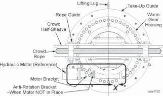
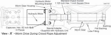
5. Using the hand-held pendant on the hydraulic unit, extend the crowd screw rod until the crowd rope is tight. Back off the crowd screw rod 1/2 inch to allow for proper slack in the rope.
6. Remove the hydraulic motor from the bracket on the worm gear housing and place it in its holder on the hydraulic unit.
7. Replace the anti-rotation bracket on the worm shaft.
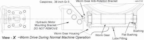
RETRACT ROPE TIGHTENING
NOTE: The constructional stretch may be out of the retract rope when it becomes necessary to adjust the rope for about the third time. Therefore, after the third rope adjustment or after replacement, back off the adjustment by one .5 inch shim after obtaining a tight rope by pressurizing the cylinders to prevent working with an overly tight rope.
NOTE: Do not overtighten the ropes. The ropes are properly adjusted when a very slight curvature is noticeable on the retract rope (a 3 to 5 inch sag) with a tight crowd rope.
With the dipper resting on the ground, rotate the crowd drum in such a way as to tighten the crowd rope and provide slack in the retract rope. Retighten the retract rope as follows:
1. Open the shim guard. 2. Clean up and grease the sliding areas on the take-up nut, support and screw. 3. Be sure that the right needle valve is open and the left needle valve is closed. 4. Extend the cylinders by injecting hydraulic fluid into the left fitting.
5. Shim the take-up nut at the desired position.
CAUTION: The take-up nut must be shimmed tight, both fore and aft, using all shims originally provided with machine.
6. Slowly open the left needle valve to release the pressure on the cylinders.
CAUTION: Oil within the needle valves is under high pressure. STAY CLEAR OF TAKE-UP NUT, SHIMS AND CYLINDERS WHEN OPERATING NEEDLE VALVE, AS THESE ITEMS COULD MOVE UNEXPECTEDLY AND CAUSE SERIOUS INJURY.
7. Close and secure the shim guard.
DIPPER TRIP ROPE REEVING & REPLACEMENT
1. Use steps one and two from Hoist Rope Reeving. In this procedure the on-board auxiliary winch is not used.
2. Trip and lock the DTB breaker in the MCC cabinet.
3. Crowd the dipper handle to unwind the trip rope from the reel. Lower the dipper to the ground and retract it slightly to get some slack in the trip rope. Remove worn rope from dipper door.
4. Open the drum guard on the dipper trip and remove the rope and wedge from the drum. Attach a work line to the trip rope. Pull the trip rope over and off of the trip rope guide sheave and lower to ground. The work rope will remain on the guide sheave and will be used to pull the new trip rope on.
NOTE: Do not use new trip rope which is longer than specified. Increasing length adds layers of rope on the drum which decreases trip torque.
5. Reeve one end of the new trip rope under the guide roller, around the latch lever sheave and secure it to the rope socket with the rope socket wedge on the dipper door.
6. Attach the other end of the new trip rope to the work line still in place on the guide sheave. With the work line, pull the trip rope onto the guide sheave and up to the dipper trip. Secure the trip rope to the drum with the rope wedge. Close the drum guard.
7. Remove the lock that was previously placed on the DTB breaker in the MCC cabinet and reset the breaker.
HOIST AND CROWD LIMIT SYSTEMS
All Bucyrus International mining shovels incorporate a PLC-based limit position system that permits the setting of the Hoist/Lower and Crowd/Retract operational limits. Hoist and crowd encoders send digital signals to the PLC relative to the hoist crowd motor positions. The setup of the hoist and crowd limits is accomplished through the operator’s display terminal by following the instructions provided here in this manual along with those on the operator’s display. When encoder calibration and hoist/crowd positional limits have been properly set the system will prevent the dipper handle from hitting its end stops and will prevent the padlocks from being pulled into the boom point sheaves.
Hoist/Crowd encoder calibration provides the limit system a reference point for tracking both the hoist and crowd positions. Performing the encoder calibration sets all the hoist and crowd limits to their previously set values in order that the actual limits do not require reset after initial commissioning.
SETTING ROPE LIMITS
CROWD STOP END LIMIT
1. Position the handle near its crowd end stop using hoist and crowd. Raise dipper to the maximum point, just touching boom point sheaves.
2. Extend the handle to its desired crowd endstop.
3. Press “ACCEPT”. This calibrates the rope lengths and setting limits. This is required only after changing ropes or adjusting the retract rope.
The slowdown limits reduce speed to 15% of maximum.
RETRACT SLOWDOWN/STOP LIMITS
1. Retract the handle until the retract stops are approximately 1.5 feet from the front end of the saddle block. Press “ACCEPT”.
2. Next, position the handle with the retract stops approximately 6 inches from the saddle block. Press “ACCEPT” to accept limit.
HOIST SLOWDOWN/STOP LIMITS
1. Position the dipper so that the padlocks are approximately 1 foot from the boom point sheaves. Press “ACCEPT” to accept limit.
2. Next, lower dipper until the padlocks are 3 feet from the boom point sheaves. Press “ACCEPT” to accept limit.
CROWD SLOWDOWN/STOP LIMITS
1. Position the handle approximately 1 foot from rear end of the saddle block. Press “ACCEPT” to accept the limit.
2. Next, retract the handle until crowd stops are approximately 2 feet from the saddle block. Press “ACCEPT” to accept the limit.
Section 6 Brakes and Couplings
Always refer to the safety information in Section 1 of this manual before starting any maintenance procedure on this machine.
Table of Contents
BRAKES .......................................................................................................................................3 Machine Motion Brakes ...............................................................................................................3 DISC BRAKE OPERATION....................................................................................................4 MAINTENANCE .......................................................................................................................4 SWING BRAKE.......................................................................................................................5 SWING BRAKE INSTALLATION ........................................................................................6 Swing Brake Assembly ...............................................................................................................6 Swing Brake Friction Disc Inspection ..........................................................................................8 SWING BRAKE BURNISHING ..........................................................................................8 CROWD BRAKE ..................................................................................................................10 Crowd Brake Assembly ..............................................................................................................10 Crowd Brake Tachometer ...........................................................................................................11 HOIST BRAKE......................................................................................................................13 HOIST BRAKE ADJUSTMENT ........................................................................................14 Hoist Brake Friction Plate Inspection .........................................................................................14 HOIST BRAKE INSTALLATION .......................................................................................15 PROPEL BRAKE..................................................................................................................16 PROPEL BRAKE ADJUSTMENT....................................................................................16 Propel Brake Assembly .............................................................................................................17 SPRING REPLACEMENT-ALL BRAKES..............................................................................18 COUPLINGS ...............................................................................................................................20 GRID COUPLINGS................................................................................................................20 LUBRICATION .................................................................................................................20 COUPLING DISASSEMBLY AND GRID REMOVAL ........................................................21 GRID COUPLING INSTALLATION ...................................................................................21 GRID COUPLING ALIGNMENT .......................................................................................24 Grid Coupling Data .....................................................................................................................24 GEAR COUPLINGS ..............................................................................................................25 INSTALLATION ................................................................................................................25 GEAR COUPLING ALIGNMENT ......................................................................................27 Gear Coupling Data ....................................................................................................................27 ELASTOMERIC COUPLINGS.....................................................................................................28 PM COUPLING ASSEMBLY ..................................................................................................28 COUPLING INSTALLATION...................................................................................................28 MOUNTING HUBS TO SHAFTS............................................................................................31 KEYED SHAFTS.............................................................................................................31 KEYLESS FITS...............................................................................................................31 FITTING THE RUBBER ELEMENTS....................................................................................32 FITTING SEQUENCE............................................................................................................32
BOLTING UP FLANGES........................................................................................................33 BOLT TIGHTENING TABLE .......................................................................................................33 END GAP TABLE ......................................................................................................................34 COUPLING ALIGNMENT .......................................................................................................34 AXIAL ALIGNMENT...........................................................................................................35 RADIAL ALIGNMENT .......................................................................................................35 ANGULAR ALIGNMENT ...................................................................................................35 ALIGNMENT TABLE ..................................................................................................................35 INSPECTION.........................................................................................................................36 INSPECTION TABLE.................................................................................................................36
BRAKES
Section 6 Brakes and Couplings
This machine uses spring-set, air-released disc brakes on the HOIST, DRAG, PROPEL and SWING motions.
In the event of a power failure or loss of air pressure, the brakes will automatically set to stop the machinery motion. Pressure switches located near each brake control valve monitors air pressure at the brake. The brakes cannot be released for operation until the air pressure reaches the operating pressure.
Each brake is fitted with a proximity sensor to monitor lining wear and a limit switch to monitor the brake set or released position. When the lining wear limit is reached, it is announced on the operator’s display terminal. The brake position is announced in the operator’s control screen.
Machine Motion Brakes
DISC BRAKE OPERATION
When air is exhausted, the spring force “Clamps” the rotor between the friction discs or the mounting flange and pressure plate. To disengage the brake, air enters through the end plate into the diaphragm cavity. As air pressure increases, the end plate moves away from the stationary spring housing. The pressure plate is bolted to the end plate and travels in the same direction compressing the springs and releasing the brake.
DANGER: PRIOR TO INSTALLATION OR MAINTENANCE ON A BRAKE, MAKE SURE THAT MACHINE OR MACHINERY IS BLOCKED TO PREVENT MOVEMENT. Failure to do so could result in serious personal injury or machine damage.
CAUTION: Protective means must be used to prevent oil or grease from coming into contact with the disc(s) or the friction discs. Oil or grease will significantly reduce the torque capacity of the brake and decrease its ability to hold the machinery in a safe position. DO NOT RISK INJURY!
CAUTION: DO NOT OPERATE THE MACHINE WITHOUT ALL BRAKE GUARDS INSTALLED.
MAINTENANCE
• No lubrication is required.
• Replace friction disc(s) when worn to the step on the friction disc O.D.
SWING BRAKE
SWING BRAKE INSTALLATION
The tachometer, furnished with the electric motor, must be installed before installing the swing brake assembly. Refer to the figure on the previous page for the correct orientation.
NOTE: Tachometer will only be installed on one of the two swing motors. Due to mechanical coupling the 2 swing motors and gearcases will operate at identical speeds.
1. Install the drive hub and keyway on the motor. Refer to PINION & HUB INSTALLATION in Section 9 - ENGINEERING DATA.
2. Install motor shaft nut and secure to shaft with lockwasher by bending tabs over flats.
Swing Brake Assembly
3. Install brake adapter onto the motor and secure with hardware. Use care to align the access slots in the adapter for future tachometer inspections.
4. Lightly coat the splines of the drive hub with a teflon grease allowing only a thin film of lubricant to remain on the splines. Excess grease will be thrown outward by centrifugal force and have a degrading effect on the brake.
5. Using a lifting device and the holes provided in the outer portion of the drive ring, place the brake assembly onto the drive hub and lower while aligning the splines in the drive hub with those in the brake disc.
6. Apply 30-50 PSI compressed air to the brake to release it.
NOTE: The brake will be fully released once air pressure exceeds 28 PSI on a properly functioning brake. However air pressure in excess of 125 PSI could damage the internal seals of the piston.
7. Install shims, as required, to achieve a gap of 0.015 - 0.030 inch between the pressure plate and the friction surface of the brake disc.
CAUTION: A minimum of 30 PSI must remain applied to the brake while this dimension is determined. The brake must remain fully disengaged!
8. Release the air pressure from the brake piston to relax the internal springs.
9. Tighten the brake housing for final installation.
10. Apply air pressure as in step 6. Verify that the proper gap remains between the pressure plate and friction surface of the disc.
11. Install safety guard around the brake assembly.
12. If previously removed, install the micro-switches and brackets for the wear and release indicators.
Swing Brake Friction Disc Inspection
SWING BRAKE BURNISHING
The swing brake on this machine is a “single disc assembly” consisting of a ductile iron disc to which multiple metallic lining segments are riveted. The burnishing-in procedure for a new or relined disc brake initiates a controlled wear process to develop the maximum contact area between braking surfaces. The burnish-in process will also start the formation of an oxide layer on the surface of the linings to stabilize and to establish the coefficient of friction.
Prior to beginning the burnishing procedure check and record the brake pressure plate temperature with a hand held temperature measuring device. Between each stop, continue monitoring the pressure plate temperature. Do not allow the pressure plate temperature to exceed 300° Fahrenheit (149°C).
NOTE: Check the temperature of each brake on the machine. If the temperature exceeds 300°F (149°C) stop the burnishing procedure and allow the brakes to cool to 200°F (93°C). If overheated or malfunctioning brakes are found, check if the brake is releasing properly. It is normal for a small amount of disc particles to be ejected from the brake and for sparking to occur during this operation. Large amounts of either situation may indicate overheating or improper release and should always be corrected prior to continuing.
BURNISH-IN PROCEDURE (DIPPER EMPTY) # of Stops at Speed Time Between Stops
4 stops/1/4 speed 1 minute minimum 8 stops/1/2 speed 2 minutes minimum Perform one additional full load, 3/4-speed stop with the dipper handle in the horizontal position and the hoist rope vertical on the swing motion. This will ensure that the brakes are functional. Record the swing stopping times and angles. Forward these recorded readings to the Bucyrus International service department.
CROWD BRAKE
Crowd Brake Assembly
Crowd Brake Tachometer
Installation of the tachometer, furnished with the electric motor, is required before beginning to install the crowd brake assembly. Install the tachometer and the torque arm in relation to the image provided.
1. Install the drive hub and keyway on the motor. Refer to PINION & HUB INSTALLATION in Section 9 - ENGINEERING DATA.
2. Install the motor shaft nut and secure to the shaft with the lockwasher by bending the tabs over the flats.
3. Install the brake adapter onto the motor and secure with hardware. Use care to align the access slots in the adapter for future tachometer inspections.
4. Lightly coat the splines of the drive hub with a teflon grease allowing only a thin film of lubricant to remain on the splines. Excess grease will be thrown outward by centrifugal force and have a degrading effect on the brake.
5. Using a lifting device and the holes provided in the outer portion of the drive ring, place the brake assembly onto the drive hub and lower while aligning the splines in the drive hub with those in the brake disc.
6. Apply 30-50 PSI compressed air to the brake to release it.
NOTE: The brake will be fully released once air pressure exceeds 28 PSI on a properly functioning brake. However, air pressure in excess of 125 PSI could damage the internal seals of the piston.
7. Install shims, as required, to achieve a gap of 0.015 - 0.030 inch between the pressure plate and the friction surface of the brake disc.
CAUTION: A minimum of 30 PSI must remain applied to the brake while this dimension is determined. The brake must remain fully disengaged!
8. Release the air pressure from the brake piston to relax the internal springs.
9. Tighten the brake housing for final installation.
10. Apply air pressure as in step 6. Verify that the proper gap remains between the pressure plate and friction surface of the disc.
11. Install safety guard around the brake assembly.
HOIST BRAKE
HOIST BRAKE ADJUSTMENT
The hoist brake is equipped with 2 adjustment shims to compensate for lining wear. This brake should be checked daily for lining wear and proper piston travel. If out of adjustment it will not be able to support a fully loaded dipper. To inspect for excessive disc wear use a micrometer as shown in the image below. The reading must be taken from the same location with the brake engaged and released. Due to the tapered surface of the pressure plate, care must be taken to duplicate the position and process as closely as possible. Friction disc adjustment must be performed when the total wear reaches .400 inch.
View - A Hoist Brake Friction Plate Inspection
NOTE: Adjustment shims are split for ease of removal and installation. DO NOT DISCARD shims after removal during brake adjustment. These shims will be required when reassembling brake following a friction disc replacement.
1. When wear has reached 0.400 inch, remove the outer cylinder nuts and a single shim from the stack.
2. Reinstall the nuts and tighten to a maximum of 120 Ft.Lbs.
CAUTION: Tighten the stud nuts as per the instructions on the brake drive ring to a maximum of 120 Ft.Lbs. Excessive or improper tightness can cause the drive ring to become deformed and seriously reduce the effectiveness and life of the brake assembly.
3. Re-check to total cylinder movement. If total movement is greater than .270 inch, place the unit back into service.
If the brake has already had a single shim removed, a second adjustment is possible. If the brake movement is greater than 0.400 inch the second shim may be removed using the same steps as for the first shim.
NOTES: •When removing the second shim the friction discs and center plates be removed and inspected. Use care during disassembly to keep track of the order in which the components were removed.
•If the wear is unequal between the inner and outer friction discs they should be reversed during reinstallation (Place the inner disc to the outside and the outer disc to the side nearest the motor).
• Always be certain the machined step on the disc (near the center) is facing the motor during installation.
•Replace the brake piston and nuts. Tighten to a maximum of 120 Ft.Lbs. as above and check total piston movement. If the movement is greater than 0.270 inch the brake can be returned to service.
HOIST BRAKE INSTALLATION
The tachometer, furnished with the electric motor, must be installed before installing the brake assembly.
1. Install the drive hub and keyway on the motor. Refer to PINION & HUB INSTALLATION in Section 9 - ENGINEERING DATA.
2. Install motor shaft nut and secure to shaft with loctite.
3. Install brake adapter onto the motor and secure with hardware. Use care to align the access slots in the adapter for future tachometer inspections.
4. Lubricate the hub and friction disc splines with a light coat of teflon grease or anti-seize compound.
5. Install the friction discs and center plates onto the shaft adapter in the required order before sliding on the brake assembly. Tighten the drive ring hardware and install the brake guard.
PROPEL BRAKE
The brake friction discs should be inspected monthly by removing the air hole guard and measuring the distance between the pressure plate and the cylinder. The measurement should be taken with the brake engaged and again with the brake disengaged. If the difference between the two measurements is 0.31 inch or greater, the brake must be adjusted or the friction discs replaced.
PROPEL BRAKE ADJUSTMENT
The brake is equipped with three 0.094 inch thick shims located between the drive ring and the cylinder. Before removing a shim, check the friction disc assembly for unequal wear. If the discs are wearing unequally (inside vs. outside), additional brake life can be achieved by reversing the disc assemblies. With two shims out, allowable piston travel before friction disc replacement is 0.31 inch. When piston travel reaches 0.31 inch, remove one shim as follows:
CAUTION: NEVER ALLOW THE BRAKE TO OPERATE WITH PISTON TRAVEL OF LESS THAN 0.220 inch. Removal of shims prior to normal wear adjustment requirements will not increase brake holding capacity. Premature shim removal will reduce running clearances, causing premature wear and heat damage to linings and brake. CAUTION: THE THIRD SHIM MUST NEVER BE REMOVED FOR ADJUSTMENT PURPOSES AS DAMAGE CAN OCCUR TO PRESSURE AND WEAR PLATES.
1. With the machine parked on flat level surface, with dipper heel resting on the ground, remove the tach cover, the tach, the tach supports and the brake guard.
2. Apply air pressure to the brake to release it. Back-off on the cylinder stud nuts 0.06 inch.
3. Spread one shim at the split line and remove it from brake. For ease of removal, the shims are split radially. Take care not to bend or spring the shim when removing. Save shims for reuse when new replacement friction discs are installed.
NOTE: For ease of removal, shims are split radially.
4. Retighten the cylinder stud nuts in criss-cross to 90-100 Ft.Lbs. and check piston travel. Depressurize brake.
CAUTION: Do not overtighten the stud nuts as this will cause drive ring distortion and lead to excessive wear on brake disc and mating surfaces.
5. Reinstall the brake guard, the tach supports, the tach and the tach cover.
Propel Brake Assembly
SPRING REPLACEMENT-ALL BRAKES
To replace the brake springs, disassemble the brake as follows:
1. Follow steps one through five of the Replacement of Friction Discs procedure.
2. Remove the cylinder stud nuts.
NOTE: It is recommended that the piston cylinder, pressure plate and drive ring be marked so that the same studs pass through the same bolt holes at reassembly.
Remove the piston with cylinder and pressure plate as a complete assembly from the studs and place on a clean level working area.
3. Slowly open the temporary shut-off valve and release pressure from the piston with cylinder and pressure plate assembly.
CAUTION: The brake springs are under compression. Care must be taken when removing piston bolts in order to avoid injury.
4. Remove all piston bolts except for four located at 90° from one another.
NOTE: Reinstall one piston bolt to the right of each of the four remaining piston bolts, turning each of the reinstalled piston bolts two turns. These bolts act as a safety stop during the removal of the four remaining piston bolts 90° from each other.
5. Carefully loosen each of the four remaining piston bolts two turns each in a pattern 180° opposite each other until all four piston bolts have been loosened two turns. Repeat loosening each of the four piston bolts in the above manner until the brake spring compression has been fully released at all four remaining piston bolts.
CAUTION: Tap the piston to make sure it has not bound against the cylinder. Care must be taken when loosening piston bolts so that the piston does not bind against the cylinder.
6. Remove the four remaining piston bolts and the safety stop bolts and lift the cylinder with piston off the pressure plate and brake springs.
7. Remove all brake springs and insulating washers.
NOTE: The springs are equipped with insulated fiber washers. Be sure the washers are in place at reassembly.
8. Place new insulating washers, then new springs into the counterbores of the pressure plate. Reposition the cylinder with piston onto the springs taking care that each spring end properly seats into each counterbore of the brake cylinder.
9. Using piston bolts, assemble the cylinder with piston to the pressure plate and springs by reversing step 4 above. Tighten all piston bolts to 200-220 Ft.Lbs. in a pattern 180° apart.
10. Close the temporary shut-off valve. Reconnect the auxiliary air line to the temporary shut-off valve and follow steps four and five of the Replacement of Friction Discs procedure.
11. Slide the pressurized piston with cylinder and pressure plate assembly onto the cylinder studs. (When applicable, make sure cylinder shimming is in place between the cylinder and drive ring.) Secure the assembly in place with the stud nuts. Tighten the nuts in a diametrical pattern to 90-100 Ft.Lbs.
CAUTION: Do not overtighten the stud nuts as this will cause drive ring distortion leading to excessive wear on brake disc and mating surfaces.
NOTE: Observe the temporary regulator pressure gauge. If the pressure has dropped, the piston O-Rings may need replacement.
9. Open the temporary shut-off valve and release the brake pressure. Remove the temporary regulator with gauge and the shut-off valve from the brake inlet and reconnect the brake air line to the brake inlet.
10. Reinstall the brake guard, the tach supports, the tach and the tach cover.
COUPLINGS
GRID COUPLINGS
These instructions apply to Tapered Grid Couplings. They are designed to operate in either the horizontal or vertical position without modification. However, for vertical applications, the match mark shown above, must be up. The performance and life of the couplings depend largely upon how they are installed and serviced. Carefully follow these instructions for optimum performance and troublefree service.
All coupling parts have identifying part numbers. When ordering parts, always SPECIFY SIZE and TYPE. Cover halves have 1/8 NPT lube holes. Use a standard grease gun and lube fitting.
LUBRICATION
Adequate lubrication is essential for proper operation of the coupling. Refer to the table for the amount of lubricant required. It is recommended that the coupling be checked once a year and lubricant added if required. For extreme or unusual operating conditions, check more frequently. Grid couplings initially lubricated with LTG will not require re-lubrication until the connected equipment is stopped for servicing.
COUPLING DISASSEMBLY AND GRID REMOVAL
DANGER: STORED ENERGY! Once grid is removed, machinery is free to rotate and brake will no longer hold. Equipment must be blocked prior to doing any maintenance to prevent unwanted movement. Death, serious injury, or damage to the machine can result from failure to take proper measures to prevent movement due to release of energy.
Whenever it is necessary to disconnect the coupling, remove the cover halves and grid. A round rod or screwdriver that will conveniently fit into the open loop ends of the grid is required. Begin at the open end of the grid section and insert the rod or screwdriver into the loop ends. Use the teeth adjacent to each loop as a fulcrum and pry the grid out radially in even, gradual stages, proceeding alternately from side to side.
GRID COUPLING INSTALLATION
Only standard mechanics tools, wrenches, a straight edge and feeler gauges are required for installation. For instructions on mounting to a drive motor, refer to the appropriate motor shaft installation instructions in this manual.
1. Mount Seals and Hubs
Clean all parts. Heat hubs in an oven or use suitable dry heat. DO NOT rest gear teeth on container bottom or apply flame directly to gear teeth. DO NOT heat hubs over 275oF (135oC) for mounting.
Lightly coat seals with grease and place them on shafts BEFORE mounting hubs. Mount hubs on their respective shafts so the hub face is flush with the end of its shaft.
2. Gap and Angular Alignment
Use a spacer bar equal in thickness to the gap specified. Insert the bar, as shown here, to the same depth at 90o intervals and measure clearance between bar and hub face with feelers. The difference in minimum and maximum measurements must not exceed the ANGULAR limit specified.
NOTE: The motor shaft must be at the mid-point of its end play when measuring the gap.
3. Offset Alignment
Align hubs so that a straight edge rests squarely (or within the limit specified) on both hubs as shown here. Check at 90o intervals with feelers. The clearance must not exceed the OFFSET limit specified. Tighten all foundation bolts and repeat Steps 2 and 3. Realign coupling if necessary.
NOTE: Use a dial indicator for more accurate alignment.
4. Insert Grids
Pack gap and grooves with specified lubricant before inserting grids. Install grid segments so that all cut ends extend in the same direction; this will assure correct grid contact with non-rotating pin in cover halves. Spread grid segments slightly to pass over the coupling teeth and seat with a soft mallet.
5. Pack with Grease and Assemble Covers
Pack the spaces between and around the grid with as much lubricant as possible and wipe off excess flush with top of grid. Position seals on hubs to line up with grooves in cover. Position gaskets on flange of lower cover half and assemble covers so that the match marks are on the same side as shown above. If shafts are not level (horizontal) or coupling is to be used vertically, assembly cover halves with the lug and match mark up, or on the high side. Secure covers halves with fasteners and tighten to torque specified in the coupling data table. MAKE SURE LUBE PLUGS ARE INSTALLED BEFORE OPERATING!
6. Periodic Lubrication
Remove both lube plugs and insert a lube fitting. Fill with recommended lubricant until an excess appears at hole opposite; then insert plug. Lubricate couplings at least once ever year. Lubricate more frequently when exposed to excessive-moisture, extreme temperatures, rapid reversing or shock loads or excessive misalignment. It is not necessary to re-lube couplings filled with Long Term Grease (LTG) until disassembled for service to attached components.
GRID COUPLING ALIGNMENT
Grid Coupling Data
Coupling Crowd Propel *Part No.········C113194-01 ······S021581 Type·············· Grid············· Grid Motor Frame··············812·············812 # Bolts···············14················8 Dia. (inch)···············0.5·············0.75 Torque (in.lbs.)··············650·············650 Torque (Ft.Lbs.)···············54···············54 Max. Parallel Offset (in.)·············0.022···········0.022 Max. Angular Limit (in.)··············0.04············0.04 Min. End Gap Limit (in.)·············0.556···········0.556 Grease Wt. (Lbs.)···············1.6··············1.6
NOTES: • Bolts are NOT Standard Fasteners. Values indicated are for clean, dry threads.
• * Use Parts Book to Verify Part Number.
WARNING: DO NOT SUBSTITUTE STANDARD FASTENERS FOR COUPLING BOLTS.
GEAR COUPLINGS
INSTALLATION
1. Clean all parts. Heat hubs in an oven or use suitable dry heat. DO NOT rest gear teeth on container bottom or apply a flame directly to gear teeth. DO NOT heat hubs over 275oF (135oC) for mounting. Refer to motor shaft installation for hubs mounted on drive motors.
Pack sleeve teeth with grease and lightly coat seals with grease BEFORE assembly. DO NOT DAMAGE THE SEALS.
Use a dial indicator to align dynamically balanced couplings and assembly parts with mating match marks aligned. Mount the indicator on one hub and take readings for the OFFSET check on the O.D. of the other hub. The difference between the minimum and maximum readings DIVIDED by two should not exceed the values in the table. For ANGULAR check, take readings on either face of other hub. The difference between the minimum and maximum readings should not exceed the values in the gear coupling data table.
2. Mount the flanged sleeves, seal and hubs. Place the flanged sleeves WITH the seal rings on the shafts before mounting the hubs.
CAUTION: DO NOT DAMAGE THE SEALS. Mount the hubs on their respective shafts, as shown, so that each hub is flush with its shaft end. Position the equipment in approximate alignment with the approximate gap specified in the table.
3. Gap and Angular Alignment - Use a spacer bar equal in thickness to gap specified in Table. Insert bar, as shown, to same depth at 90o intervals and measure clearance between bar and hub face with feelers. The difference in minimum and maximum measurements should NOT exceed the ANGULAR limit specified in the table.
4. Clamp a dial indicator to the rigid hub as shown and rotate the rigid hub one complete turn. The total indicator reading DIVIDED by two must not exceed the OFFSET limit specified. Tighten all foundation bolts and repeat Steps 3 and 4. Realign coupling if necessary. Grease the hub teeth.
5. Insert gasket, DO NOT DAMAGE the GASKET, between flanges. Position flanged covers with lube holes at 90o and draw flanged cover into position. Use bolts, nuts and lockwashers furnished with couplings.
IMPORTANT: Tighten the flange bolts and nuts to the torque specified in the table.
6. For TYPE G couplings, fill with recommended grease until excess appears at the open hole; then insert plug. For TYPE GV couplings, proceed as outlined above. IN ADDITION, when flex hub is on TOP, vent by inserting a .010 thick SMOOTH feeler gauge between seal and hub. Fill until excess appears at feeler. Repeat at 90o intervals.
CAUTION: Make certain all plugs are inserted after lubricating.
GEAR COUPLING ALIGNMENT
Gear Coupling Data
Coupling Swing *Part No.····················C111720-01 Type·························· Gear Motor Frame···························812 # Bolts·····························8 Dia. (inch)··························0.625 Torque (in.lbs.)·························· 1500 Torque (Ft.Lbs.)···························125 Max. Parallel Offset (in.)··························0.119
NOTES: • Bolts are NOT Standard Fasteners. Values indicated are for clean, dry threads.
• * Use Parts Book to Verify Part Number.
WARNING: DO NOT SUBSTITUTE STANDARD FASTENERS FOR COUPLING BOLTS.
PM COUPLING ASSEMBLY ELASTOMERIC COUPLINGS
HOIST COUPLING SHAFT PART NO. S031382, PM 60
COUPLING INSTALLATION
1. MOUNT HUBS TO SHAFTS
Place the cover over the shaft. Fit the keys to shaft. Heat the inner member and driving flange. Fit the hubs to the shafts.
2. FIT RUBBER ELEMENTS
Brush the coupling cavities and rubber elements with silicone fluid. Fit the elements in the sequence shown below.
Set the shaft end gap and tighten the cover and flange bolts.
Check the axial, radial and angular alignment of coupling.
Check the alignment of the coupling. Remove the cover and examine the rubber elements for signs of damage. Refer to “INSPECTION” below.
MOUNTING HUBS TO SHAFTS
KEYED SHAFTS
The coupling is supplied loosely assembled along with assembly instructions and silicone fluid. After installation, the instructions should be passed on to the end user. Completely disassemble the coupling. If the coupling has limitied end float pads (blue or white circular pads located in the inner member of the coupling) remove them. Check the shaft diameters and coupling bores.
CAUTION: Unless a split cover is supplied with the coupling, fit the cover over the shaft before fitting the inner member to the shaft.
• Heat the hub to 250oF in either an oil bath or oven. Lift the hub from the heating device either by using steel lifting chains wrapped around the blades of the inner member or by using steel chains and shackles inserted through the bolt holes (take care not to damage the surface of these holes). Handle hot components with extreme care. Make sure that the lifting chains hold the hub securely.
• With the key in place in the shaft, fit the hub to the shaft. The end face of the inner member or drive flange should be flush with the end of the shaft unless otherwise specified.
KEYLESS FITS
• Specific instructions are supplied with couplings which have high interference keyless fits. Please refer to these instructions when mounting the hubs.
FITTING THE RUBBER ELEMENTS
The rubber elements may be fitted either before or after the coupling flange is bolted up. All PM couplings up through size PM 60 have 1 rubber element in each cavity. Size PM 90 up to PM 600 have 2 rubber elements in each cavity.
Refit the limited end float pads, if supplied (circular blue or white buttons). Place the outer member of the coupling over the inner member. Set the axial position of the outer member relative to the inner member. The outer member should be centered axially over the inner member. Fit the rubber elements in the sequence shown in the diagram below.
FITTING SEQUENCE
To ease installation of the rubber elements, silicone fluid should be used as a lubricant. Use a fluid which has a viscosity between 1000 and 3000 cs. Brush each rubber element and the cavities of the couplings with the fluid before inserting the rubber elements.
BOLTING UP FLANGES
• All the rubber blocks should be in place and the driving and driven machinery should be brought together with the correct gap between the ends of the shafts. The shaft end gap is shown on the drawing and in the table below.
• Fit the cover and secure with bolts. Do not force the rubber elements into their cavities by tightening the cover bolts. Note that couplings size PM 180 and above use through bolts to secure the cover.
• Connect the two halves of the coupling using the bolts supplied with the coupling. It will be easier to fit these bolts if their shanks are coated with an anti-seize lubricant.
• Bolts normally have metric threads. Their sizes are shown in the table. Tighten the bolts to the torque values shown in the table.
BOLT TIGHTENING TABLE
Coupling Flange Bolt Cover Bolt Size SizeTorque Size Torque
PM 0.4 M8 17 ft-lb M8 17 ft-lb PM 0.7 M8 17 ft-lb M8 17 ft-lb PM 1.3 M8 17 ft-lb M8 17 ft-lb PM 3 M8 17 ft-lb M8 17 ft-lb PM 6 M8 17 ft-lb M8 17 ft-lb PM 8 M12 63 ft-lb M10 33 ft-lb PM 12 M12 63 ft-lb M12 63 ft-lb PM 18 M16 162 ft-lb M16 162 ft-lb PM 27 M16 162 ft-lb M16 162 ft-lb PM 40 M16 162 ft-lb M16 162 ft-lb PM 60 M20 266 ft-lb M20 266 ft-lb PM 90 M20 266 ft-lb M20 266 ft-lb PM 130 M24 461 ft-lb M24 461 ft-lb PM 180 M24 461 ft-lb M24 461 ft-lb PM 270 M30 922 ft-lb M30 922 ft-lb PM 400 M36 1615 ft-lb M36 1615 ft-lb PM 600 M36 1615 ft-lb M36 1615 ft-lb
END GAP TABLE
COUPLING ALIGNMENT Coupling Shaft End Size Gap (in)
PM 0.4 0.04 PM 0.7 0.08 PM 1.3 0.08 PM 3 0.12 PM 6 0.12 PM 8 0.12 PM 12 0.14 PM 18 0.16 PM 27 0.18 PM 40 0.20 PM 60 0.22 PM 90 0.26 PM 130 0.28 PM 180 0.31 PM 270 0.35 PM 400 0.41 PM 600 0.47
The following describes how to verify that the alignment of the coupling is sufficient to prevent premature deterioration of the rubber elements. Note that the values given in the table are in inches.
AXIAL ALIGNMENT
Use a straight edge held on face “A” and a depth gage to measure the distance between faces “A” and “B”. Check the measurement with the allowable values given in the table.
RADIAL ALIGNMENT
Mount the dial indicator to the shaft at “C” with the pointer at “D” as shown in the diagram. The total reading on the dial indicator for one complete turn of the drive (maximum reading minus minimum reading) should be less than the value shown in the table.
ANGULAR ALIGNMENT
Mount the dial indicator to the shaft at “C” with the pointer at “E” as shown in the diagram. The total reading on the dial indicator for one complete turn of the drive (maximum reading minus minimum reading) should be less than the value shown in the table.
ALIGNMENT TABLE
INSTALLATION ALIGNMENT VALUES Coupling Minaxial Maxaxial Radial Angular (inch) (inch) (inch) (inch)
PM 0.4 0.622 0.638 0.008 0.011 PM 0.7 0.657 0.681 0.008 0.013 PM 1.3 0.776 0.799 0.008 0.016 PM 3 0.500 0.524 0.012 0.019 PM 6 0.303 0.327 0.015 0.019 PM 8 0.340 0.369 0.016 0.021 PM 12 0.396 0.431 0.016 0.024 PM 18 0.413 0.453 0.016 0.027 PM 27 0.509 0.554 0.019 0.032 PM 40 0.538 0.588 0.021 0.036 PM 60 0.623 0.677 0.024 0.041 PM 90 0.736 0.800 0.028 0.047 PM 130 0.792 0.861 0.032 0.053 PM 180 0.906 0.984 0.034 0.066 PM 270 1.038 1.127 0.038 0.079 PM 400 1.228 1.331 0.045 0.091 PM 600 1.358 1.476 0.051 0.103
INSPECTION
Check the alignment of the coupling and the condition of the rubber elements annually.
The results should be compared to the maximum values listed below.
INSPECTION TABLE
MAXIMUM ALIGNMENT VALUES Coupling Minaxial Maxaxial Radial Angular (inch) (inch) (inch) (inch)
PM 0.4 0.599 0.661 0.031 0.046 PM 0.7 0.622 0.716 0.031 0.054 PM 1.3 0.740 0.835 0.031 0.062 PM 3 0.465 0.559 0.047 0.076 PM 6 0.266 0.364 0.059 0.076 PM 8 0.295 0.414 0.063 0.084 PM 12 0.345 0.482 0.063 0.096 PM 18 0.354 0.512 0.063 0.110 PM 27 0.443 0.620 0.075 0.126 PM 40 0.465 0.661 0.083 0.144 PM 60 0.542 0.758 0.094 0.165 PM 90 0.640 0.896 0.110 0.188 PM 130 0.689 0.964 0.130 0.213 PM 180 0.788 1.102 0.138 0.264 PM 270 0.905 1.260 0.154 0.318 PM 400 1.073 1.486 0.181 0.366 PM 600 1.181 1.653 0.205 0.411
To inspect the rubber elements, unbolts the cover of the coupling so that the faces of the rubber blocks can be seen. It is not necessary to remove the rubber elements from the couplings. The rubber elements should be replaced if any of the following are found:
• Deep cuts, over 10% of the width of the rubber elements.
• Rubber elements which are loose in their cavities.
• Rubber elements with cracked or sticky surfaces.
Large amounts of rubber dust and an impression of the coupling inner member on the cover are signs of excessive misalignment.
NOTE: For replacement parts, refer to the parts catalog for this machine. The type of element used can be identified by a round colored sticker molded into each rubber element. When ordering replacements, specify the color and number (60, 70, 80) printed on the sticker.
Section 7 Compressed Air System
Always refer to the safety information in Section 1 of this manual before starting any maintenance procedure on this machine.
Table of Contents
AIR COMPRESSOR.....................................................................................................................3 Air Compressor Installation .........................................................................................................4 Air Compressor ...........................................................................................................................5 THE COMPRESSION CYCLE................................................................................................6 Screw Compressor - Compression Cycle .....................................................................................6 AIR FLOW...............................................................................................................................7 Screw Compressor ......................................................................................................................7 OIL FLOW...............................................................................................................................7 COMPRESSOR MAINTENANCE............................................................................................8 PRESSURE SWITCH .......................................................................................................8 Pressure Switch Adjustment .......................................................................................................8 AIR FILTER........................................................................................................................8 FILTER ELEMENT.......................................................................................................9 MOTOR LUBRICATION..................................................................................................10 COMPRESSOR LUBRICATION.....................................................................................10 SYNTHETIC LUBRICANTS .......................................................................................11 HIGH TEMPERATURE OPERATION ........................................................................11 ADDITION OF OIL BETWEEN SCHEDULED CHANGES........................................12 OIL LEVEL GAUGE....................................................................................................12 OIL CHANGE INTERVAL ...........................................................................................12 DRAINING AND CLEANING THE OIL SYSTEM .........................................................13 COMPRESSOR OIL FILTER..........................................................................................13 OIL COOLER..................................................................................................................13 OIL SEPARATOR............................................................................................................14 REPLACEMENT OF OIL SEPARATOR ELEMENT...................................................14 PRESSURE DROP CHECK...........................................................................................15 DRIVE BELT TENSION...................................................................................................15 BELT TENSION ADJUSTMENT.................................................................................16 COMPRESSOR PREVENTIVE MAINTENANCE CHECKLIST.......................................16 LOCKOUT VALVES....................................................................................................................17 Lockout Valve Locations ............................................................................................................17 Lube Room Lockout Valves .......................................................................................................18 SAFETY WARNINGS ............................................................................................................19
SCHEMATIC, AIR .............................................................................................................. (insert)
AIR COMPRESSOR
Section 7 Compressed Air System
This machine uses a single-stage, positive-displacement rotary compressor which utilizes intermeshing helical rotors to effect the compression action. Both the rotors are supported by largecapacity, anti-friction bearings which are located outside the compression chamber.
The compressor is mounted in a welded frame assembly on the left side of the machine within the machinery house.
The air inlet port is located on top of the compressor near the driveshaft end. The discharge port is near the bottom on the opposite end of the compressor.
DANGER: STORED ENERGY! Air under pressure will cause severe personal injury or death. Shut down compressor and relieve system of all pressure before removing components such as valves, plugs, fittings and bolts.
Air Compressor Installation
Air Compressor
For further specific information on the air compressor, refer to the compresor manufacturer’s manual supplied with this machine.
THE COMPRESSION CYCLE
Compression is accomplished by the main and secondary rotors synchronously meshing in a onepiece cylinder. The main (driven) rotor has four helical lobes 90° apart from one another lengthwise. The secondary (idler) rotor has six matching helical cut flutes placed 60° apart in order to allow meshing with the main rotor.
Screw Compressor - Compression Cycle
The compression cycle begins as the rotors begin to un-mesh at the inlet port and the air is drawn into the cavity between the main rotor lugs and the secondary rotor’s flutes (figure A). When the rotors pass the inlet port’s cutoff, the air is trapped in the cavity between the two rotors (figure B). As the rotational meshing continues, a greater amount of the main rotor lobe will enter the secondary rotor flute and the air volume is reduced as the pressure of the air increases. Oil is introduced to reduce the heat of compression and provide sealing for the internal clearances between the rotors. Volume reduction and pressurization will increase as the rotation continues until the air/oil mixture passes the discharge port (figure C) and is released to the oil reservoir.
AIR FLOW
Air enters the unit through a dry pleated air filter and passes through the inlet manifold and an antiblowback unloader valve to the compressor. While passing through the compressor, oil is introduced to the compressed air. At the compressor discharge port the air/oil mixture passes into the oil reservoir where most of the suspended oil is removed. A change in velocity as it forms droplets causes oil to form which fall back to the reservoir. A multiple-element final separator removes the remaining oil and returns it to the compressor oil tank. The air is then allowed to pass to the service valve for intended usage.
Screw Compressor
NOTE: This system is not intended for use where oil-free air is required.
OIL FLOW
Air pressure constrained within the oil reservoir forces oil to pass through the oil cooler and filter assembly to provide the compressor with lubricating oil. A portion of the oil is directed through internal passages to all the bearings ensuring complete lubrication of moving parts. The balance of the oil is injected directly into the cylinder for cooling and lubrication of the rotors and to provide sealing for the internal rotor clearances.
COMPRESSOR MAINTENANCE
PRESSURE SWITCH
An adjustable pressure switch controls motor and unloader shutdown along with the load/unload signals. The factory setting is at 25 PSI for the differential pressure between the settings that load and unload signals are introduced. This is the maximum differential pressure allowed with this switch. The cutout, or unload, is set at the factory. Refer to the figure.
The cutout pressure is set by the adjustment screw “A”. The differential pressure can be increased by movement of adjustment screw “B” in a clockwise direction. Do not force this adjustment beyond its limits as this will result in an unreliable differential pressure. There will normally be no need to adjust the factory setting.
Pressure Switch Adjustment
CAUTION: DO NOT ADJUST THE CUTOUT PRESSURE HIGHER THAN THE MAXIMUM UNIT RATING. Minimum operating pressure is 25 PSI for short periods (under 3 minutes) and 40 PSI for sustained operation.
AIR FILTER
The air filter must receive adequate maintenance if maximum service life is to be received from the compressor unit.
NOTE: A wide range of operating hours is possible between servicing intervals of the air filter. The environmental conditions encountered will directly affect this interval. Conditions may vary with regard to the location and dust conditions that will affect machine operation. Experience and a series of systematic checks will aid in determining the interval required.
FILTER ELEMENT
The filter element should be serviced when inspection reveals an accumulation of dirt and debris on the outside of the element. An interval with a maximum inspection time of 48 operating hours is suggested initially, with a service interval of no more than 500 operating hours between inspections.
The element should be replaced after a series of 8 cleaning cycles or if inspection revels a rupture, hole, or tear in the filter media. Inspection should be accomplished by placing a bright light source within the filter element and visually inspecting from the outside.
To service the filter:
1. Remove the filter element from the filter housing.
2. Remove excess dirt and debris with a compressed air nozzle at a maximum of 40 PSI. When blowing the accumulations off the filter pleats, angle the air stream parallel to the pleats or use a slightly inward angle. To prevent damage, do not point the blow gun to blast air perpendicular to the filter element pleats.
For elements contaminated with dry dirt deposits only:
Submerge the element and allow to soak in a solution of warm water and mild detergent for approximately 5 minutes. Gently agitate by hand for an additional minute or two.
For elements contaminated with oil or greasy dirt deposits:
a) Submerge the element in a well mixed solution of 1 gallon warm water, 4 tablespoons mild detergent and 1/2 teaspoon of tri-sodium phosphate. Allow to soak for approximately 5 minutes. Gently agitate by hand for an additional minute or two.
b) Remove the element from the solution and discard the solution.
c) Prepare a second batch of the cleaning solution and immerse the filter element for an additional 5 minutes. Gently agitate by hand for an additional minute or two. 3. Remove the filter element from the solution and gently rinse with fresh water. Do not apply pressure perpendicular to the filter. Ensure a gentle stream is used for this operation to avoid tearing the filter element.
4. Inspect the filter element carefully for rupture or severe deformity. Replace defective filters at once. Use a bright light from inside the filter to check for blockages in the filter element. Replace the filter element, or reclean if necessary to remove blockages.
5. Allow the filter element to air-dry before reinstallation.
CAUTION: Do not oil this filter element. Use only suggested cleaning solvents. Never operate the compressor without a serviceable filter element in place.
NOTE: It is advisable to keep a spare filter element(s) on hand to minimize down time. Store all replacement filter elements in an area where they will be protected from damage, dirt, oil and moisture. Handle filter parts with care.
MOTOR LUBRICATION
The ball bearing motors shipped with this unit will contain sufficient grease for an extended operating period. However; re-lubrication at intervals consistent with the usage listed in the table below will provide the protection required for maximum bearing life. Re-lubricate with a grease of the following specifications:
Compressor Motor Lubricant Specifications Worked Penetration 265-296 Oil Viscosity (CSU @ 100°F) 400-550 Soap Type Lithium N-H Bomb, min. hours for 20 PSI drop at 210°F. 750 Bleeding, max. weight % in 500 hours @ 212°F 10 Rust Inhibiting Yes
Compressor Motor Re-Greasing Schedule Type of Service Typical Example Re-Lubrication Interval Standard 1 or 2 shifts daily 4 years Severe 24 hours/day - 365 days/year 1 ½ years
COMPRESSOR LUBRICATION
The compressor oil system consists of the oil reservoir, cooler and filter assemblies. The oil is circulated through the system by means of a pressure differential and provides 3 functions with the compressor: 1) cooling, 2) lubrication and 3) the sealing of internal passages. The capacity of the compressor lubrication system is 5-6 gallons.
The recommended compressor lubricant is Gardner-Denver GD800 Lubricating Coolant with the exception of the High Temperature Operation section listed in SYNTHETIC LUBRICANTS below. GD800 is a superior petroleum based lubricant formulated with additives specifically designed for use in “Electra-Saver” compressors and is suitable for year round operation.
Compressor Lubricant Recommendations Recommended Oil Temperature Range Gardner-Denver GD800 Lubricant/Coolant Year round operation @ discharge temperatures up to 200°F Gardner-Denver GD8000 Lubricant/Coolant If conditions may require over 4 hours sustained operation @ a discharge temperature above 200°F
CAUTION: The mixing of different types of lubricants, or the use of incorrect or inferior lubricants will result in the formation of heavy varnish deposits and sludge throughout the system.
SYNTHETIC LUBRICANTS
Certain synthetic lubricants such as synthetic hydrocarbons, diester or polyesters offer an extended drain interval when used in screw type compressor applications. A superior diester type lubricant is available in Gardner-Denver “GD8000” Lubricating Coolant which will extend lubrication change intervals from two to four times that found when using GD800. A properly utilized lubricant analysis program can dramatically maximize the change interval.
CAUTION: DO NOT MIX GD800 and GD8000 Lubricating Coolants or any other synthetic and petroleum based lubricants.
CAUTION: Regardless of the synthetic lubricant change interval used, oil filter and oil separator change intervals remain the same as for GD800.
HIGH TEMPERATURE OPERATION
If the discharge temperature is to be above 200°F for a period of 4 hours, use GD8000 which is a synthetic diester lubricant. Short periods of up to four hours sustained discharge temperatures of up to 200°F do not require a change from the year-round GD800 fluid.
When converting to GD8000 fluid, the original lubricant should be completely drained and the system flushed prior to refilling with the new type lubricant. Complete draining will require the removal of all plugs within the compressor, oil reservoir and lines. In some applications piping may require removal to ensure complete draining. In order to ensure complete removal of the old fluid, it is suggested that after 100 hours operation with the new fluid, the case be drained and refilled with GD8000 fluid.
CAUTION: DO NOT MIX GD800 and GD8000 Lubricating Coolants or any other synthetic and petroleum based lubricants.
CAUTION: Do not set the High Discharge Air Temperature switch to a setting above 225°F to compensate for high temperature operation.
CAUTION: Use caution when selecting GD8000 lubricating fluid. Some components within the system, such as the lubricator bowl gaskets and valve trim, may not be compatible with the synthetic fluid. Be sure to check with the component supplier for any issues regarding compatibility.
ADDITION OF OIL BETWEEN SCHEDULED CHANGES
Addition of oil to the system is required when the oil level is below the RUN mark while the unit is in operation.
DANGER: Be sure to stop the unit and drain the oil reservoir pressure before attempting to add fluid.
1. Wipe away all dirt and material around the oil filler plug. 2. Remove filler plug and add lubricant of the same type as is currently in the compressor in order to return the level to the center of the RUN range when the unit is operating. The amount required to raise the level from the top of the ADD range to the centerline of the RUN range is approximately ½ gallon.
NOTE: Repeated addition of oil between scheduled replacements may indicate excessive oilcarryover and should be investigated.
OIL LEVEL GAUGE
The oil level gauge indicates the amount of oil within the reservoir while the unit is in operation. When the unit is stopped the gauge will indicate a higher level. When the unit is operating the ideal oil level will be near the center of the RUN range on the gauge. Under normal circumstances the oil level will fluctuate slightly as the compressor loads and unloads.
NOTE: Drain oil only when the gauge indicates an excess level while the compressor is under load.
OIL CHANGE INTERVAL
The frequency of oil changes is determined by the air filter maintenance performed along with the operating conditions and the quality of the oil. The recommended practice is to change the oil often enough so that the drained oil is relatively clean. Under normal operating conditions (not a severe environment), GD* lubricant can be used for up to 2,000 hours between changes. When the operating conditions are extremely severe more frequent changes will be necessary.
NOTE: The compressor oil filter must be changed at 1,000 hour intervals!
DANGER: Be sure to stop the unit and drain the oil reservoir pressure before attempting to add fluid.
DRAINING AND CLEANING THE OIL SYSTEM
Always drain the complete system. Draining the oil while it is hot will aid in the prevention of varnish deposits and assist in the flushing away of impurities within the system. For proper draining of the system employ one of the following methods:
• If the unit is not elevated high enough to use the oil reservoir drain valve, a small hand, electric, or pneumatic pump may be used.
• If the unit is adequately elevated to use the oil reservoir drain valve, open the valve and drain the fluid into an appropriate container for storage or disposal.
• If the drained oil and/or filter element are contaminated with dirt, flush the entire system. This will include the reservoir, oil cooler, mixing valve and associated lines. Inspect the oil separator elements for dirt accumulation and replace if necessary. If varnish deposits are discovered, contact the factory for recommendations on varnish removal and prevention measures.
COMPRESSOR OIL FILTER
A spin-on oil filter is mounted on the side of the compressor unit. Filter maintenance is vital to trouble free operation. The filter is disposable. It is also equipped with an internal relief valve that will open in the event of a clogged filter element in order to not restrict oil flow.
Remove the filter by spinning the filter in a counter-clockwise direction. The filter can be drained and discarded in an appropriate manner consistent with environmental controls.
NOTE: When the filter is replaced between oil changes, 1 quart of the appropriate fluid must be added to the system to replace the volume contained in the filter.
Replace the filter by spinning the filter onto the fitting in a clockwise direction. The filter must only be tightened hand tight. If the filter is installed with excessive force the packing on the sealing surface may become torn or deformed, allowing leakage to occur. Add one quart of fluid after replacement of filter.
IMPORTANT: After initial start-up of the compressor the filter should be changed after 100 hours of operation.
Under routine maintenance the oil filter should be replaced after each 1,000 hours of operation.
OIL COOLER
The compressor oil cooler fan is directly connected to the motor shaft. The fan exhausts air pulled through the cooler, away from the unit. It is important to keep both sides of the cooler core clean for efficient operation and optimum cooling of the fluid. Do not allow items to block airflow on either side of the cooler as fluid heat can damage the compressor.
OIL SEPARATOR
The compressor oil separator is located in the oil reservoir. It contains a one-piece agglomerator element to remove oil from the air stream of the system. Oil from inside the compressor is returned through tubing to the compressor cylinder. Oil through the service lines may be due to the oil level being too high. This may be caused from excessive foaming, a clogged return oil line, a return pickup tube being loose or broken or by operation at a pressure below the minimum specified. If it has been determined that none of the previously listed possibilities are at fault, inspect the element within the separator for rupture. A rupture may be caused by heavy dirt or varnish deposits resulting from inadequate air filter servicing, use of an improper oil, or using the same oil for too long a period of operation. Collapsing of the element is usually due to heavy dirt or varnish buildup in the filtering material.
REPLACEMENT OF OIL SEPARATOR ELEMENT
To remove the agglomerator element for inspection or replacement:
1. Disconnect all tubing. Disconnect a union within the discharge line to release any possibility of trapped pressure.
2. Remove the bolts securing the top plate on the oil reservoir. In order to avoid puncture of the separator, lift the top plate straight up until the oil return tube has completely cleared the separator.
3. Lift the element from the reservoir using care not to dent or damage the element.
4. Inspect the element by placing a bright light source within the element and looking for deposits of heavy dirt or varnish, or ruptures. Pay close attention to the gaskets which are bonded to each side of the separator flange.
Installation of the element is the reverse of disassembly.
NOTES: • During installation of the element, the top plate bolts must be tightened to a value of 150 Ft.Lbs. • Element life will vary greatly depending on the severity of the service environment and the quality of the oil in use. The condition of the oil can be determined by performing a pressure drop check as described later.
PRESSURE DROP CHECK
A pressure drop check is performed to evaluate the condition of the separator element and lubricant oil within the compressor reservoir and system.
1. Connect a pressure gage within the system (as shown below) so that a reading may be taken on either side of the separator.
2. The pressure differential is measured by alternately opening and closing the valves.
3. If the pressure differential exceeds 8 PSI the separator should be changed.
The savings from electrical usage alone will outweigh the cost of the new element and the system will operate at optimum efficiency.
NOTE: Do not attempt to clean the separator element - it must be replaced!
DRIVE BELT TENSION
Proper drive belt tension and alignment are provided initially at the factory. Check belt tension and alignment prior to initial start-up of the unit. The sheaves should be aligned with a straight edge. The tension should be just adequate to prevent a “squeal” on start.
To remove the belts:
1. Remove the fan shroud from the cooler assembly. 2. Remove the belt guard from the motor. 3. Loosen the motor mount bolts which extend through the base of the motor housing. 4. Using the 2 adjustment bolts provided, release the pressure from the belts adequately to remove them from the sheaves of the pulleys.
Installation of the belts is the reverse operation of the removal.
NOTE: Be sure not to over-tighten the belts before securing the motor mount bolts. Refer to the following for proper belt tension adjustment.
BELT TENSION ADJUSTMENT
Belt tension should be adjusted to the absolute minimum amount which will allow the belts to rotate without an initial “squeal” from slippage during start-up of the unit. The following information is a general guideline to achieve the approximate dimension required. Fine tuning may be required.
CAUTION: Do not over-tighten the belts. Permanent damage to the compressor and motor bearings and shafts may result.
COMPRESSOR PREVENTIVE MAINTENANCE CHECKLIST
Hours of Operation Required Maintenance 8 hours 1.Check oil reservoir level - add if required. 2.Observe if the unit loads/unloads properly. 3.Drain moisture traps on air receiver and separator* 125 hours 1.Check for accumulation of foreign matter on oil cooler and aftercooler* core faces. 2.Check for accumulation of foreign matter on the fan and fan motor. 1,000 hours Replace oil filter. 2,000 hours Replace compressor oil and filter. Adverse conditions may dictate a more aggressive maintenance schedule.
* if used
LOCKOUT VALVES
A series of lockout valves are provided to enable maintenance personnel to isolate and remove compressed air from the swing, crowd, hoist and propel brakes should they require maintenance. This permits air flow to continue to the other brakes and features of the machine.
CAUTION: Isolating only one feature of the the machine will not eliminate the danger of machine motion while maintenance is being performed. The user is responsible to ensure that all proper precautions, including lock-out/tag-out, bracing and any other necessary precautions have been taken, so that no unanticipated machine motions will occur.
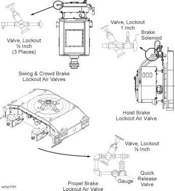
Lockout Valve Locations
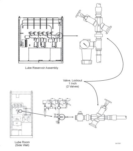
Lube Room Lockout Valves
SAFETY WARNINGS
Ensure all personnel are aware of, and adhere to the instructions of the following safety labels which are mounted on the compressor.
Section 8 Air Filtration
Always refer to the safety information in Section 1 of this manual before starting any maintenance procedure on this machine. Table of Contents
HOUSE FILTER FANS..................................................................................................................3 LUBRICATION .........................................................................................................................3 DYNAVANE AIR CLEANER .....................................................................................................4 Filter Components Overview .......................................................................................................4 TENKAY FILTER.....................................................................................................................5 Front View of Tenkay Filter Installation........................................................................................5 Rear View of Tenkay FIlter Installation ........................................................................................ 6 AIR CONDITIONER ......................................................................................................................7 SPECIFICATIONS ...................................................................................................................8 Air Conditioner ~ Block Diagram .................................................................................................8
Section 8 Air Filtration
HOUSE FILTER FANS
Check the blades for grease and/or dirt accumulation. Clean if necessary. Blades should rotate freely without binding.
If vibration is detected, check the following:
1. Bearing and drive alignment 2. Shaft straightness 3. Wheel or sheaves loose on shaft 4. Loose or worn bearings 5. Loose mounting bolts 6. Motor out-of-balance 7. Sheaves out-of-balance 8. Nose cap loose on wheel 9. Worn or corroded wheel 10. Accumulation of material on the wheel 11. Cracks on blades and/or at the hub 12. Worn fan blades and hubs
LUBRICATION
All bearings are pre-lubricated and sealed at the factory. Under normal temperature condition (20° to +150°F), when the fans are circulating clean air, the bearings are considered lubricated for life and additional lubrication is unnecessary.
If the fans are circulating contaminated air, or operating at elevated temperatures, periodic lubrication is required. For normal temperatures, a high quality, light, neutral mineral grease is used. It is free of abrasive fillers and highly resistant to oxidation. When fans are operating at elevated temperatures (166°F or higher), silicone or lithium soap base grease should be used. This high temperature grease should have a breakdown point above 350°F.
Use a low pressure grease gun for fan bearings. Either the gun or the fitting should be vented. To prevent overfilling apply a small amount of grease. This is especially important when extended lubrication piping is used and the bearing cannot be observed.
DYNAVANE AIR CLEANER
Dynavane air cleaners are self-cleaning and do not require the routine service typical of air filters which collect and hold the dirt removed from the air. There are a few maintenance procedures which should be observed. • The air entering the side of the cells should be kept free of rags, leaves and papers to assure free airflow. Applications exposed to this type of material should have intakes covered with a course mesh (5 mesh) screen to prevent entry of material larger than the bleed slot.
Filter Components Overview • Check the bleed system to make sure nothing has impaired bleed air flow. • The cells should be examined for buildup of deposits on the blades. A light coating of dust is normal and will not impair the operation or efficiency of the cell. Occasionally, due to the presence of oil mist or similar vapors in the air, heavier surface accumulations will occur and the cell will require cleaning. Cleaning the cells can be accomplished by brushing the surface of the blades or blowing down with compressed air. • Another method of cleaning the Dynavane filters is to reverse the direction of fan rotation. This creates reverse air pressure which helps free up the dirt. The units can be removed for a more thorough cleaning.
TENKAY FILTER
The Farr Tenkay filter is an aspirated cartridge, self cleaning dust filter. Incoming air passes from the outside to the inside of the cartridges.
This unit will clean itself during operation. Periodic lubrication is not required for this unit. Replace the Tenkay cartridges when required. Do not allow dust to collect in the hopper.
Detailed information on the Tenkay filter system may be found in the Vendor’s data provided with the machine.
Front View of Tenkay Filter Installation
Rear View of Tenkay FIlter Installation
AIR CONDITIONER
SIGMA MPV9 climate control units are heavy duty systems providing superior performance in a variety of climate and environmental conditions.
Air is drawn from beneath the unit, passes over the heat exchanger coil and the heating elements into a double-wheel fan where it is discharged through the base of the unit into the conditioned space below.
The refrigerant is metered by an externally mounted TX valve, and is cut off by a liquid line solenoid valve. The heat exchanger is large, constructed of heavy gauge tubing with a coarse fin pitch to reduce clogging. The fan motor is a large shaft, totally enclosed unit that is air cooled.
All pressure controls within the evaporator unit are fully sealed, preset and O-ring connected.
The compressor is a heavy duty, fully-sealed scroll-type device. The unit is mounted in flexible mounts in an effort to reduce noise and vibration. All connections are either soldered, O-ring type or rotalok.
A large liquid drier is placed within the liquid line to filter moisture from the refrigerant. The condenser operates at a single speed only.
SPECIFICATIONS
Nominal Cooling Capacity 31,000 Btu/hr@460V/60Hz Power requirements 380V/3ph/50Hz 415V/3ph/50Hz 460V/3ph/60Hz 17.5 Amps 19.0 Amps 21.0 Amps Refrigerant HFC 134a – 24 lbs. Oil POE Variety Mobil Arctic EAL22CC or ICI Emcarate RL32CF Compressor Fully sealed, scroll type Condensor Coil 5 row, 3/8 inch copper tube with 8 aluminum fins/inch Evaporator Coil 4 row, 3/8 inch copper tube with 10 aluminum fins/inch
Detailed information on the MPV9 can be found in the vendor’s documentation that accompanied the machine and the General Arrangement drawings provided by Bucyrus International.
Air Conditioner ~ Block Diagram
Section 9 Engineering Data
Always refer to the safety information in Section 1 of this manual before starting any maintenance procedure on this machine.
Table of Contents
CAPSCREW (BOLT) GRADE......................................................................................................3 BOLT TIGHTENING.......................................................................................................................4 TORQUE WRENCH METHOD...............................................................................................4 Table 1 - Lubricated or Plated Threads or with Hardened Washers..............................................4 Table 2 - Dry Threads..................................................................................................................4 TURN-OF-NUT METHOD .......................................................................................................5 Table of Snug Tight Torque Values .............................................................................................5 WIRE LOCKING CAPSCREWS...................................................................................................6 Patterns for Wirelocking Capscrews ...........................................................................................6 TORQUE NUT INSTALLATION .....................................................................................................7 TIGHTENING PROCEDURE FOR ONE 2-INCH TORQUE NUT...........................................7 TIGHTENING PROCEDURE FOR ONE 3-INCH TORQUE NUT...........................................8 TIGHTENING PROCEDURE ~TORQUE ROD, TAPERED SLEEVE & 1.0 INCH NUT.........9 TIGHTENING PROCEDURE ~TORQUE ROD, TAPERED SLEEVE & 1.62 INCH NUT.....10 TIGHTENING PROCEDURE ~SWING TORQUE ROD & TAPERED SLEEVE...................11 TORQUE NUT REMOVAL PROCEDURE............................................................................13 THREAD LUBRICATION .................................................................................................13 TORQUE NUT HELPFUL HINTS..........................................................................................14 LOCKING ASSEMBLIES .............................................................................................................15 LOCKING ASSEMBLY REMOVAL .........................................................................................16 PINION AND HUB INSTALLATION...............................................................................................17 REMOVAL FROM A SHAFT...................................................................................................17 MOUNTING A PINION OR HUB ON A SHAFT .......................................................................17 HUB ADAPTER PRE-HEAT ADVANCE REQUIREMENTS.............................................20 MOTOR COUPLING PRE-HEAT ADVANCE REQUIREMENTS.....................................20 MAINTENANCE WELDING .........................................................................................................21 WELDING ELECTRODES...................................................................................................22 REPAIR WELDING OF CRACKS.........................................................................................23 Joint Preparation for Repair of Cracks.......................................................................................23 PREHEAT........................................................................................................................24 WELDING TECHNIQUE..................................................................................................24 REPAIR WELDING OF BROKEN PARTS............................................................................25 REPAIR WELDING SWING RACK TEETH...........................................................................26 PREPARATION ...............................................................................................................26 SWING RACK WELDING ELECTRODES.....................................................................27 PREHEAT........................................................................................................................27 WELDING PROCEDURE...............................................................................................28
WELDING AND CUTTING EQUIPMENT .....................................................................................30 STRESS RELIEVING & TEMPERATURE MEASURING EQUIPMENT .......................................30 WIRE ROPE CARE AND MAINTENANCE..................................................................................32 STORAGE.............................................................................................................................32 CHECKING DIAMETER ........................................................................................................32 Correct Method for Checking Wire Rope Diameter .....................................................................32 HANDLING WIRE ROPE......................................................................................................33 Improper Methods for Uncoiling Wire Rope ................................................................................34 SEIZING WIRE ROPE...........................................................................................................34 END PREPARATIONS/TERMINATIONS ...............................................................................35 WIRE ROPE CLIPS..............................................................................................................36 WIRE ROPE CLIP APPLICATION...................................................................................36 WEDGE SOCKETS........................................................................................................38 INSPECTION OF SHEAVES AND DRUMS...........................................................................39 Examples of Sheave Groove Conditions .....................................................................................39 Groove Gauge for New or Re-Worked Sheaves ..........................................................................39 Inspecting for Worn Sheave .......................................................................................................40 BREAKING IN A NEW WIRE ROPE.....................................................................................40 INSPECTION DATA...............................................................................................................41 GUIDELINE TO INSPECTIONS AND REPORTS...........................................................42 Wire Rope Stretch vs Rope Life.................................................................................................44 Examples of Broken Wires........................................................................................................47 SEALS.........................................................................................................................................48 SEAL INSTALLATION ............................................................................................................48 GEARCASE SEALING ..........................................................................................................50
Section 9 Engineering Data
CAPSCREW (BOLT) GRADE
The grade classification of a capscrew (bolt) is identified by the marks on the head as shown below:
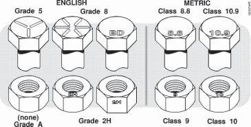
Use the SAME GRADE washer and nut as the capscrew. NEVER SUBSTITUTE A LESSER GRADE CAPSCREW IN PLACE OF THAT WHICH IS SPECIFIED.
BOLT TIGHTENING
TORQUE WRENCH METHOD
The following tables show torque values for bolt grades 2, 5 and 8 with UNC threads only. Table 1 lists torque values for lubricated or plated threads and for using hardened washers. Table 2 lists those for dry threads.
The bolts should be tightened to the specified total value in increments, alternating from bolt to bolt to assure gradual, even pull-up of mating parts. Tightening should progress systematically from the most rigid part of a joint to its free edges.
Circular bolt patterns should be tightened in a diametric crosshatch pattern while applying torque in increasing values to ensure proper pullup of parts.
Table 1 - Lubricated or Plated Threads or with Hardened Washers
Table 2 - Dry Threads
TURN-OF-NUT METHOD
CAUTION: THIS TIGHTENING PROCEDURE IS ONLY APPLICABLE FOR BOLT GRADES 5 AND 8 WITH UNC THREADS. For bolts with other than UNC threads, contact the Bucyrus International Service Department.
NOTE: When using this procedure the bolt threads and the surfaces under the bolt head and nut must be lubricated. This procedure is applicable only if the joint and under head surfaces for bolt and nut are machined for parallelism.
1. The bolts should be brought to a “snug tight” condition to insure that the parts of the joint have good contact with each other. “Snug Tight” is defined as the tightness attained by torquing a bolt to the value specified in the table on the following page. Snug tightening should progress systematically from the most rigid part of the joint to its free edges while alternating from bolt to bolt to assure gradual even pull up of the mating parts. After all bolts have been snugged, the first bolts tightened at the most rigid part of the joint should be rechecked for proper torque retention. If these bolts are loose due to pull up of the joint, the snug tightening sequence should be repeated for all bolts in the connection. This rechecking and re-torquing procedure should be repeated as many times as is required until the joint is completely pulled up and all bolts are at the specified “snug tight” torque. Tightness of the mating surfaces of the joint should then be verified by using feeler gauges.
Table of Snug Tight Torque Values
2. The nuts and bolts should then be matched marked by center punching the bolt end and nut. On rod bolts match mark both rod ends and nuts. The bolts and nuts should then be tightened additionally by the applicable amount of nut rotation as specified in Table 4. It is not necessary to follow any particular bolt to bolt sequence during this portion of the “turn of the nut” tightening.
NOTE: Nut rotation is read between the punch mark on the bolt and the punch mark on the nut. For rod bolts, nut rotation is the cumulative total rotational movement between punch marks on both ends of the rod bolt.
WIRE LOCKING CAPSCREWS
Wire locking of capscrews is used when maximum lock assurance is required when periodic visual inspection is not possible.
The illustrations below show the recommended wire locking methods for various right hand thread capscrew patterns. For patterns not shown, wire lock the screws “in pairs”. For odd numbered patterns, wire lock the screws in pairs except the remaining 3 capscrews wire lock together
Patterns for Wirelocking Capscrews
Use 14 gauge soft annealed lockwire. Thread the wire through the capscrew head so that tightening stress on the wire will exert a tightening torque on the direction of capscrew thread. (The illustrations show lock wire threading for right hand threaded capscrews. Reverse the lock wire patterns shown for left hand capscrews.)
TORQUE NUT INSTALLATION
TIGHTENING PROCEDURE FOR ONE 2-INCH TORQUE NUT
1. Ensure that a special steel washer, supplied with the torque nut, is placed beneath the torque nut. DO NOT USE STANDARD COMMERCIAL WASHERS.
2. Check the base of the torque nut to ensure that all jackbolts are flush with the bottom.
3. Spin the torque nut onto the rod or bolt by hand.
4. Tighten the jackbolts to 100 Ft.Lbs. as follows:
a. Snug all jackbolts to 10 Ft.Lbs. each.
b. Using the STAR pattern shown, tighten all jackbolts to 50 Ft.Lbs.
c. Switch to the circular pattern shown and tighten all jackbolts to 75 Ft.Lbs.
d. Continue with the circular pattern and tighten all jackbolts to 110 Ft.Lbs.
NOTES: • With longer rods and bolts, stretch in the rod or bolt occurs during tightening of the jackbolts. Therefore, after tightening with the circular pattern in step 4-d above, the first jackbolt may have loosened. The higher torque value is used in this step only to speed the tightening process. After performing the above steps, use a torque wrench for the final torque values and continue tightening the jackbolts in a circular pattern until all jackbolts are tightened to a value of 100 Ft.Lbs.
• An impact wrench can be used for the initial tightening sequences, however a torque wrench must be used to achieve the final torque values. • Repeat the above steps for all remaining torque nuts.
TIGHTENING PROCEDURE FOR ONE 3-INCH TORQUE NUT
1. Ensure that 2 special steel washers, supplied with the torque nut, is placed beneath the torque nut. DO NOT USE STANDARD COMMERCIAL WASHERS.
2. Check the base of the torque nut to ensure that all jackbolts are flush with the bottom.
3. Spin the torque nut onto the rod or bolt by hand.
4. Tighten the jackbolts to 200 Ft.Lbs. as follows:
a. Snug all jackbolts to 10 Ft.Lbs. each.
b. Using the STAR pattern shown, tighten all jackbolts to 100 Ft.Lbs.
c. Switch to the circular pattern shown and tighten all jackbolts to 150 Ft.Lbs.
d. Continue with the circular pattern and tighten all jackbolts to 220 Ft.Lbs.
NOTES: • With longer rods and bolts, stretch in the rod or bolt occurs during tightening of the jackbolts. Therefore, after tightening with the circular pattern in step 4-d above, the first jackbolt may have loosened. The higher torque value is used in this step only to speed the tightening process. After performing the above steps, use a torque wrench for the final torque values and continue tightening the jackbolts in a circular pattern until all jackbolts are tightened to a value of 200 Ft.Lbs.
• An impact wrench can be used for the initial tightening sequences, however a torque wrench must be used to achieve the final torque values. • Repeat the above steps for all remaining torque nuts.
TIGHTENING PROCEDURE ~TORQUE ROD, TAPERED SLEEVE & 1.0 INCH NUT
1. Check the base of the torque nut to ensure that all jackbolts are flush with the bottom.
2. Insert the expansion sleeve from the top of the structure.
3. Insert the tapered stud into the sleeve. Note the direction of the taper on the rod.
4. Slip the special washer (spacer) over the lower threaded end of the stud.
5. Spin the lower torque nut onto the stud by hand.
6. Tighten the lower nut jackbolts to 27 Ft.Lbs. as follows:
a. Snug all jackbolts to 5 Ft.Lbs. each.
b. Using the STAR pattern shown, tighten all jackbolts to 15
Ft.Lbs.
c. Switch to the circular pattern shown and tighten all jackbolts to 20 Ft.Lbs.
d. Continue with the circular pattern and tighten all jackbolts to 30 Ft.Lbs. Refer to the notes below.
7. Ensure that a special steel washer, supplied with the torque nut, is placed beneath the upper torque nut. DO NOT USE STANDARD COMMERCIAL WASHERS.
8. Spin the upper torque nut onto the stud by hand. Using the STAR pattern shown, tighten all jackbolts to 10 Ft.Lbs.
NOTES: • With longer rods and bolts, stretch in the rod or bolt occurs during tightening of the jackbolts. Therefore, after tightening with the circular pattern in step 4-d above, the first jackbolt may have loosened. The higher torque value is used in this step only to speed the tightening process. After performing the above steps, use a torque wrench for the final torque values and continue tightening the jackbolts in a circular pattern until all jackbolts are tightened to a value of 27 Ft.Lbs.
• An impact wrench can be used for the initial tightening sequences, however a torque wrench must be used to achieve the final torque values. • Repeat the above steps for all remaining torque nuts.
TIGHTENING PROCEDURE ~TORQUE ROD, TAPERED SLEEVE & 1.62 INCH NUT
1. Check the base of the torque nut to ensure that all jackbolts are flush with the bottom.
2. Insert the expansion sleeve from the top of the structure.
3. Insert the tapered stud into the sleeve. Note the direction of the taper on the rod.
4. Slip the special washer (spacer) over the lower threaded end of the stud.
5. Spin the lower torque nut onto the stud by hand.
6. Tighten the lower nut jackbolts to 49 Ft.Lbs. as follows:
a. Snug all jackbolts to 10 Ft.Lbs. each.
b. Using the STAR pattern shown, tighten all jackbolts to 25
Ft.Lbs.
c. Switch to the circular pattern shown and tighten all jackbolts to 35 Ft.Lbs.
d. Continue with the circular pattern and tighten all jackbolts to 55 Ft.Lbs. Refer to the notes below.
7. Ensure that a special steel washer, supplied with the torque nut, is placed beneath the upper torque nut. DO NOT USE STANDARD COMMERCIAL WASHERS.
8. Spin the upper torque nut onto the stud by hand. Using the STAR pattern shown, tighten all jackbolts to 10 Ft.Lbs.
NOTES: • With longer rods and bolts, stretch in the rod or bolt occurs during tightening of the jackbolts. Therefore, after tightening with the circular pattern in step 4-d above, the first jackbolt may have loosened. The higher torque value is used in this step only to speed the tightening process. After performing the above steps, use a torque wrench for the final torque values and continue tightening the jackbolts in a circular pattern until all jackbolts are tightened to a value of 49 Ft.Lbs.
• An impact wrench can be used for the initial tightening sequences, however a torque wrench must be used to achieve the final torque values. • Repeat the above steps for all remaining torque nuts.
TIGHTENING PROCEDURE ~SWING TORQUE ROD & TAPERED SLEEVE
1. The jack bolt threads, tapered portion of the rod bolt and the expansion sleeve ID are prelubricated with graphite lube. Ensure that this lube is present. Apply additional lube as needed. Also apply a thin film of lube to the OD of the expansion sleeve, the revolving frame and swing girder bores, and the jack bolt end faces and threads.
2. Check the base of the torque nut to ensure that all jackbolts are flush with the bottom.
3. Insert the expansion sleeve from inside the frame structure. 4. Insert the tapered stud into the sleeve. Note the direction of the taper on the rod. 5. Slip the special washer (spacer) over the outer threaded end of the stud.
6. Spin the outer torque nut onto the stud by hand. 7. Tighten the outer nut jackbolts to 182 Ft.Lbs. as follows: a. Using the star pattern shown, snug all jackbolts (one round only) to approx. 30 Ft.Lbs. each.
b. Continue using the STAR pattern shown, tighten all jackbolts (one round only) to approx. 90 Ft.Lbs.
c. Switch to the circular pattern shown and tighten all jackbolts (one round only) to 182 Ft.Lbs.
d. Inside the revolving frame, measure the protrusion of the rod bolt beyond the face of the expansion sleeve flange. Refer to View - A. It must be within the acceptable range shown.
8. Ensure that a special steel washer, supplied with the torque nut, is placed beneath the upper torque nut. DO NOT USE STANDARD COMMERCIAL WASHERS. 9. Spin the upper torque nut onto the stud by hand and spin tighten against the hardened washer. 10. Finalize the preload of the inner torque nut by tightening the inner torque nut jack bolts to 182 Ft.Lbs. as follows:
a. Using the star pattern shown and a torque wrench, tighten the jack bolts (one round only) to approx. 90 Ft.Lbs. b. Set the torque wrench to 182 Ft.Lbs. Working in the circular pattern, continue tightening the jack bolts of the inner torque nut until they are stablized at full torque. This may take several rounds. (Stablized is when the torque wrench is moving less than 1/8 turn.) 11. Finalize the preload of the outer torque nut by tightening the outer torque nut jackbolts to 182 Ft.Lbs. as follows:
Set the torque wrench to 182 Ft.Lbs. Working in the circular pattern, continue tightening the jack bolts of the outer torque nut until they are stablized at full torque. This may take several rounds.
NOTES: • An impact wrench can be used for the initial tightening sequences, however a torque wrench must be used to achieve the final torque values. • Repeat the above steps for all remaining torque nuts.
TORQUE NUT REMOVAL PROCEDURE
CAUTION: THE PROPER REMOVAL OF TORQUE NUTS REQUIRES FOLLOWING STRICT PROCEDURES. LONGER ANCHOR BOLTS AND RODS REQUIRE GREATER CARE. If some jackbolts are completely unloaded prematurely, the remaining jackbolts will carry the entire load of the fastener. This may cause the jackbolts to become extremely hard to turn or even deformed.
NOTE: It is a good practice to spray the entire fastener and jackbolts with a penetrating type lubricant prior to attempting removal. This step will be critical if rust exists on the components.
1. Turn the first jackbolt counter-clockwise until it feels loose, but no more than 1/2 turn.
2. Repeat the loosening with the rest of the jackbolts. Use the reverse of the star pattern used to tighten the jackbolts. This will minimize loading on the last few jackbolts.
3. Repeat the entire loosening pattern, turning each jackbolt no more than 1/2 turn at a time, until the torque nut can be spun off the rod or bolt by hand.
After removal of the torque nut:
• Remove all jackbolts from the torque nut. Clean, inspect and lubricate the toque nut, hardened washer and the jackbolts for later reassembly.
NOTE: On smaller torque nut fasteners it may be possible to utilize impact tools to speed removal after performing step 2 above. However, DO NOT USE IMPACT TOOLS FOR THE INITIAL LOOSENING PROCEDURE. Longer anchor bolts may require several repetitions of the initial loosening process prior to switching to impact tools for assistance.
THREAD LUBRICATION
For the main studs of torque nut fasteners any standard anti-seize compound may be used. A thin, brush-on type application, or aerosol spray lubricant is acceptable.
Jackbolts are pre-lubricated from the factory with either moly or graphite lubricants depending on the intended use. Similar lubricants may be used on the jackbolt tips and hardened washer during installation.
TORQUE NUT HELPFUL HINTS
Prior to Tightening:
1. Threads: Check all threads of the main stud to verify that the torque nut will spin on freely prior to installation. If a restriction is found, use a lapping compound on the main threads or chase the threads in either the torque nut or the main stud using a good die or tap. THE
UNRESTRICTED MOVEMENT OF THE torque nut ON THE MAIN STUD IS CRITICAL IN
THE INSTALLATION PROCESS.
2. Spacers: The torque nut should be positioned at the end of the main stud when installation is complete in order to minimize exposed threads which could be damaged. This will also serve to minimize any difficulty in reaching the jackbolts and avoid the need for thinwall, or deepwell sockets. A spacer or stacked washers can be used beneath the hardened washer to accomplish this. The spacer will also allow a step-over of a damaged area on stud from repeated installations.
3. Gaps: Back off the torque nut to provide a gap of 1/16 to 1/8 inch between the torque nut and the hardened washer prior to beginning the torque application process. This will allow additional jackbolt extension which provides easy access for jackbolt tip lubrication prior to removal. When closing a gap between flanges, or where long fasteners are used, there may be insufficient jackbolt stroke to allow this step.
4. Sockets: Use only six-point quality sockets in good condition. Worn sockets will eventually round out the corners of the jackbolts possibly causing damage or injury.
While Tightening:
5. Do not tighten a jackbolt completely prior to moving on to the next jackbolt. As the torque nut is tightened, the first jackbolt that was tightened in that sequence will have a tendency to loosen. It will be faster to make multiple passes by moving quickly between jackbolts.
6. Overshoot the Target Torque as indicated PRIOR to the final tightening. This will quicken the tightening sequence by stabilizing previously tightened jackbolts sooner. BE CERTAIN NOT
TO “STABILIZE” THE JACKBOLTS AT THIS HIGHER TORQUE VALUE!
While Removing:
7. Removing the jackbolts too quickly during disassembly may increase the removal torque of the remaining jackbolts. If a jackbolt should become jammed, re-tighten several jackbolts to either side to even the tension on the torque nut.
8. If a jackbolt tip “mushrooms” it’s tip must be cut off with a cutoff wheel or abrasive disc, then the jackbolt removed.
LOCKING ASSEMBLIES
To install a locking assembly:
1. Clean and lightly oil all parts of the locking assembly, the shaft or pin and the housing bores. Be sure the bores to be connected are properly aligned.
2. Loosen all socket head capscrews on the locking assembly.
3. Install the locking assembly and the shaft or pin into the housing. Carefully note any measurements required to align the locking assembly.
4. Tighten the capscrews of the locking assembly evenly. Do not tighten each screw all at once. Instead, gradually tighten each one and proceed with the entire set, using a criss-cross pattern, and repeat until all screws are tight. Refer to the proper section of the maintenance manual for the specific torque required.
Where pilot bushings are used:
1. Insert the locking assembly as stated above - except remove all socket head capscrews.
2. Insert 3 pilot bushings, equally spaced. Insert the longer capscrews supplied with the pilot bushings.
3. Tighten the capscrews using the same procedure required for the locking assembly capscrews.
4. Once the pilot bushing is has been properly tightened, remove the longer socket head capscrews and the pilot bushings. Replace the capscrews in the locking assembly with the socket head capscrews that came with the locking assembly.
5. Tighten all capscrews using the procedure above. Retain the pilot bushings and longer capscrews for future use.
LOCKING ASSEMBLY REMOVAL
For series 1015 assemblies with a center collar:
1. Loosen all capscrews on the locking assembly by at least 2 turns in 1/4 turn increments.
2. Transfer all the capscrews to the push-off threads provided in the clamp collar and in the center collar.
3. Progressively tighten all screws in a diametrical pattern except the screws adjacent to the slit in the clamp collar these should be tightened one after the other.
For series 4000 assemblies with NO center collar:
1. Loosen all capscrews on the locking assembly by at least 2 turns in 1/4 turn increments.
2. The locking assembly incorporates a self-releasing taper, which should allow the assembly to be removed. However if the thrust rings jam, tap on the heads of 3 equally-spaced capscrews to positively release the connection.
3. Insert pullout screws in the threads under the cadmium plated locking screws to remove the assembly.
PINION AND HUB INSTALLATION
REMOVAL FROM A SHAFT
CAUTION: A properly mounted pinion, brake drum or coupling will have an interference fit with the shaft causing it to release suddenly and violently when broken loose. Loosen the shaft nut just enough to allow the pinion, brake drum or coupling to free itself. The shaft nut will stop the pinion or coupling and avoid injury to personnel.
NOTE: When removing the pinion, brake drum or coupling from a motor shaft, always use a suitable puller to avoid causing damage to either the pinion, coupling, motor frame, bearings or shaft. Do not heat the pinion, brake drum or coupling before pulling and do not use wedges between them and the bearing cap. To prevent damage to the antifriction bearings, avoid the use of a sledge hammer on the puller.
MOUNTING A PINION OR HUB ON A SHAFT
Successful operation of the gearing largely depends on the proper mounting of the pinion, brake drum or coupling on the shaft.
NOTE: Mounting pinions, brake drums or coupling by heating them in boiling water and driving them on the shaft with a blow from a heavy sledge hammer is not recommended. This results in uncontrolled advance of the pinion or coupling on the shaft. Too great an advance can cause breakage of the pinion, brake drum or coupling core, while insufficient advance can cause slippage and wear in spite of the presence of the key. In addition, hammer blows can injure the finished surface of the anti-friction bearings.
Pinions, brake drums or couplings must be mounted to a definite advance on the shaft, without hammer blows. This requires heating them to a higher temperature than is obtainable with boiling water, and is based on a difference in temperature between them and the shaft. The following is the recommended method for mounting pinions, brake drums or couplings:
1. Thoroughly clean the pinion, brake drum or coupling seating surface on the shaft and the bore of the pinion, brake drum or couplings. Use toluol or percholoethylene; do not use kerosene.
CAUTION: Solvents may be toxic or flammable. Adequate ventilation must be provided to minimize fire and health hazards. Use away from sparks, heat or flame to prevent fire or explosion. Follow the manufacturer’s instructions.
Remove any scoring from either part. Spot the cold pinion, brake drum or coupling on the shaft by hand to obtain at least a 75% fit. Check the fit with bluing. Remove the pinion, brake drum or coupling. 2. Break all sharp edges of the key and the keyway with a fine file, so there will be a radius of about 1/64 inch at each edge. Fit the key to the shaft, taking care to avoid upsetting the metal of the shaft adjacent to the key. If previously upset, file lightly, checking the fit with bluing until a 75% fit results. Try the pinion, brake drum or coupling on the shaft to make certain it does not bind on the key.
3. Mount the pinion, brake drum or coupling cold by placing it on the shaft and snapping it into position by hand. Measure the “cold” position of the pinion, brake drum or coupling using a micrometer depth gauge. The following figure illustrates the method of using the depth gauge.
Mark the places where the depth gauge was resting so measurements can be made from the same position after the pinion, brake drum or coupling has been mounted.
4. Remove the pinion, brake drum or coupling from the shaft and heat it in a suitable oven to the temperature specified. If the pinion, brake drum or coupling is heated in oil, the bore must be thoroughly cleaned before mounting. To avoid the cleaning, the use of an oven is recommended.
CAUTION: Use suitable protective equipment when handling hot items.
The pinion, brake drum or coupling temperature is indicated as a temperature difference between the shaft and pinion; this temperature difference is estimated only and can be adjusted to maintain the specified advance. Heat the pinion, brake drum or coupling in the oven until the temperature is uniform at the required number of degrees above the shaft temperature. For example, if the shaft temperature is 25oC (77oF) and the estimated difference is 125oC (225oF), heat the pinion, brake drum or coupling to 150oC (320oF) for mounting.
WARNING:Pinion, brake drum or coupling temperature must never exceed 190oC (374oF).
Some accurate method must be provided for quickly measuring the temperatures of the pinion, brake drum or coupling and shaft before mounting them. This is best done with a hand pyrometer (refer to the figure). When a hand pyrometer is not available, a centigrade thermometer can be used by placing putty over the bulb to hold it against the pinion or coupling. Heat the pinion, brake drum or coupling a few degrees above the desired temperature before removing it from the oven. Wait until it has cooled to the temperature desired, remove the thermometer and quickly mount the pinion, brake drum or coupling as described below.
5. After making sure the bore is clean, quickly mount the hot pinion, brake drum or coupling on the shaft. When it is nearly engaged with the taper fit (but not actually in contact), snap it forcible into place with a quick push. It is important that the hot pinion, brake drum or coupling be instantly snapped into position before it has cooled appreciably; otherwise it will immediately “freeze” to the shaft and cannot be adjusted further. 6. Check the “hot” or shrunk-on position of the pinion, brake drum or coupling on the shaft, using the micrometer depth gauge. The actual advance is the difference between depth gauge readings at the hot and cold positions. To control the stresses in the pinion, brake drum or coupling, the advance must be within the limits specified in the table below. If the advance is not within the limits given, the pinion, brake drum or coupling should be pulled and remounted. 7. Assemble the lockwasher and nut, tighten firmly and lock. Where a lockwasher is not used, retaining compound must be used to keep the nut tight during operation.
WARNING:When a lockwasher is used, the nut must be firmly tightened against it, then the tab on the lockwasher must be bent against the flat of the nut. This is required to keep the nut tight during operation.
HUB ADAPTER PRE-HEAT ADVANCE REQUIREMENTS
MOTOR COUPLING PRE-HEAT ADVANCE REQUIREMENTS
MAINTENANCE WELDING
These recommendations for repair welding apply to the major structural members of the machine. The high cyclic loading characteristics of the machine are considered in the design and material selected for the construction of the machine. However, due to unusual operational conditions that may be encountered and to the great number of cyclic loadings that may be applied to the machine, fatigue cracks or other abnormalities may occur. Early detection of these conditions through regular machine inspection helps to avoid problems or emergency breakdowns.
Maintenance welding is applied to the repair of cracked or broken structural components. Reconditioning of broken parts by the application of heating, cutting and welding processes requires attention to a number of details, careful adherence to the repair procedure and observance of federal, state and local safety regulations.
CAUTION: WELDING AND THERMAL-CUTTING OF METALS INVOLVE THE GENERATION OF TEMPERATURES UP TO THOUSANDS OF DEGREES AT WHICH METALS MELT AND VAPORIZE. When proper precautions are taken to protect personnel and property against the heat, evolved gases and fumes, electric shock and radiation, no harm will result either to personnel or property. In gas heating and cutting, the handling and storage of compressed gases present other hazards that also must be protected against to provide a safe working environment.
Safety precautions should conform to the latest edition of ANSI standard Z49.1, Safety in Welding and Cutting, published by the American Welding Society.
Reconditioning of failed members requires attention to a number of details and careful application of the repair procedure. Only in certain cases is it necessary to strengthen members by added reinforcement.
WARNING:REINFORCING STRUCTURAL MEMBERS SHOULD BE MADE ONLY UPON RECOMMENDATION BY BUCYRUS INTERNATIONAL, INC. IMPROPERLY APPLIED REINFORCEMENTS CAN HAVE AN ADVERSE EFFECT ON THE PERFORMANCE AND LIFE OF THE STRUCTURE.
A broken member is best repaired by making a complete penetration weld, preferably by welding from both sides, using the correct welding electrode and observing all precautions such as preheat, back-gouging, etc. The complete penetration groove weld should be ground flush with the base metal on both sides to remove all surface irregularities. An alternate procedure incorporates backup bars to ensure sound, complete penetration welds in the repair area. Be sure to follow all applicable safety measures and federal, state and local regulations.
A complete penetration weld repair conditioned by grinding instead of adding reinforcement is favored to maintain the original pattern of stress flow designed into the structural members. Addition of reinforcement which is not part of the design can reduce fatigue strength because of the change in geometry from the original structure.
Effective repair welding of cracked, broken or bent structural members of the machine involves knowledge of the types of steel used, proper welding electrodes and recognized good welding practice. The chemical composition, mechanical properties and thickness of the steel determine the welding electrode to be used and the preheat temperature required.
WELDING ELECTRODES
With the exception of the boom, weld repairs on the various structures of the machine can be made with two basic classifications of shielded metal arc electrodes: E7018 and E8018-C1. Both are low hydrogen electrodes which deposit weld metal having excellent properties at strength levels with 70,000 to 80,000 PSI, and impact properties from -20o to -75oF. These are all-position electrodes which produce high quality welds for repairing the structural components of heavy machinery.
NOTE: Although these electrodes are of superior quality, care must be exercised in their application. Low hydrogen electrodes are highly susceptible to moisture pickup after removal from sealed containers. To maintain low hydrogen, crack-resistant properties, they must be stored in electrode ovens at 250oF up to the time of use. Small portable rod ovens at the welder’s side are ideal. Use of dry low hydrogen electrodes cannot be overemphasized.
Cracks caused by hydrogen are extremely fine and occur invisibly below the surface in the base metal heat affected zone, as shown. Therefore, they are not detectable at the time of welding.
These cracks can propagate in service and lead to ultimate failure of the part. It is necessary to adhere strictly to recognized good welding practice regarding the handling, storage and use of low hydrogen electrodes. To avoid underbead cracks, remove all oil or grease or other contaminates from the surface and be sure the steel is dry.
Preheat to the required temperature. Use only dry electrodes taken from the electrode oven. After exposure to the air, the electrodes must be returned to the oven. Time limit outside the oven is four hours for E7018 and two hours for E8018C1 electrodes.
REPAIR WELDING OF CRACKS
Joint Preparation for Repair of Cracks
Remove the entire crack by arc air-gouging or grinding. Prepare a V-groove of approximately 4560o included angle for rewelding. If cracked through the full thickness and if it is possible to make the repair from both sides, a double V preparation is preferred. When welding from both sides, back-gouging for complete penetration is always recommended.
When it is not physically possible to back-gouge and weld the second side, an alternate approach must be taken. Sometimes it is possible to gouge through to completely remove the crack, then fit a backup bar on the underside to facilitate making a complete penetration weld.
NOTE: The backup bar must fit tightly to the underside otherwise poor welding conditions conducive to cracking may occur.
When it is not possible to fit a backup due to limited accessibility to the underside, it is advisable to remove a portion of the defective plate and weld in a new piece, using back up bars on all sides to ensure complete penetration welds.
A further alternative is to gouge through, removing the crack, and then weld small stringer beads to close the gap and prepare a groove for a repair weld. In this case, the repair weld will be essentially full penetration, but will be less than perfect on the under side. The other methods are preferred in the order described, that is, welding both sides, welding against a backup bar, or completely replacing a section of plate.
PREHEAT
When preheating, apply heat to a broad, general area surrounding the repair location. A soaking heat which thoroughly penetrates the material through the full thickness is preferred to high surface temperature quickly applied. Electrical resistance or radiant heating is suggested since the heat source can be left operating during welding to maintain the minimum preheat temperature. Preheat temperatures up to 400oF, depending upon the steel analysis, are adequate under most conditions for major repairs. As previously stated, preheat temperatures are determined by the type of steel in the structure. Temperatures should be measured with temperature indicating crayons.
WELDING TECHNIQUE
Maximum electrode sizes are 1/4 inch for flat position, 3/16 inch for horizontal position and 5/ 32 inch for vertical and overhead positions. Use a split weave as soon as bead width is large enough to accommodate beads side by side. Throughout all welding be certain thorough fusion with the base metal and adjacent weld beads is obtained on all weld passes. Clean off all slag between passes and all craters before starting the next electrode.
Inspect closely for cracks, undercut or overlap of beads, and gouge out or grind flaws where they occur before continuing. It is very important on highly loaded parts, particularly members subject to cyclic or dynamic stresses, to obtain sound repair welds.
The presence of any stress risers on the surface of a part is detrimental to fatigue life and can result in future cracking. Therefore, it is essential that the finished repair be smooth and well blended into the base metal. Repair weld any undercuts, grind off overlapped weld beads and blend out any notches or gouges. The best condition in a repair weld location is provided by grinding the repair smooth and flush with the surface of the base metal. Final grinding direction is to be identical with the direction of applied load on the structure. Refer to the figure.
REPAIR WELDING OF BROKEN PARTS
All recommendations given for repair of cracks apply to repair of broken parts, with additional corrections. Depending on the size and cross-section of the part, a specific sequence of welding procedures may be required in making the repair. These techniques include back-step welding sequence, block welding sequence, alternating from side to side, welding simultaneously on opposite sides, etc. All of these precautionary measures are intended to minimize shrinkage stresses and subsequent distortion or cracking during welding. The method to follow should be determined after a careful analysis of the situation and by approaching the problem with common sense. Generally a procedure which has proven successful in previous experience could logically be applied in most cases.
Use of doubling plates, stiffeners or other reinforcements to strengthen a member which has cracked in service, must be carefully considered before that repair measure is decided upon. Additional material added for strengthening alters the configuration and geometry of the member, possibly with a pronounced effect on the fatigue life of that structure. Many times, such attempts at strengthening by added plates only serves to “chase the crack someplace else.” The stress flow in the part has been altered, creating a location for stress concentration. Attachments requiring fillet welds across a tension member for example, are poor repair methods. A sound repair weld, carefully made and smoothly blended into the base metal on all sides, is preferable to additional reinforcements. Any application of reinforcements requires careful consideration regarding total overall effect on the structure during service, and should be done only after consulting Bucyrus International, Inc.
REPAIR WELDING SWING RACK TEETH
The following is a suggested method for the repair of cracked or broken swing rack teeth. The repair method should produce satisfactory results and provide a serviceable swing rack, provided the procedure is carefully followed in all details. The welding procedure is essentially the same for the three conditions shown.
PREPARATION
1. Clean off the swing rack in the area of the tooth to be repaired to remove all traces of grease, oil or dirt. Wash down thoroughly with a solvent cleaner and wipe dry with clean rags.
2. Grind to completely remove the crack and prepare a groove for welding as shown in the figures.
3. Dye penetrant test for complete crack removal.
4. In the case of a broken tooth, grind the fracture surface on the swing rack smooth and round off edges as shown.
SWING RACK WELDING ELECTRODES
1. All welding is to be done using oven dry E11018-M low hydrogen electrodes. Connect an electrode drying oven as close as possible to the work area. Set the oven temperature at 300oF. As sealed containers of electrodes are opened, place the entire contents of the container in the oven. Remove no more electrodes than can be consumed in one-half hour. If all electrodes are not used in 1/2 hour, return them to the oven. Discard any electrodes which have been wet.
PREHEAT
1. Two levels of preheat are required for tooth repair, 250oF minimum for butter welding and 175oF minimum for filling in the groove. Temperatures should be measured with temperature indicating crayons.
2. Preheat will be difficult to maintain because of the mass of metal in the swing rack to draw the heat away from the repair area. It is therefore recommended to apply heat to a large section of the swing rack to offset this quench effect. A section covering at least 3 teeth on either side of the tooth being repaired should be heated so that the minimum preheat temperature is obtained at the repair location. It is suggested that electrical resistance heaters be applied behind the teeth as shown, if such physical arrangement is possible. If the repair area cannot be heated to the required minimum temperature by this arrangement, supplementary heat must be applied from the tooth side of the swing rack. Electrical resistance heaters can be applied, or heat provided by oxy-propane torches. Adjacent areas of the swing rack should be covered with ‘heavy insulation to avoid beat loss.
NOTE: Contract services are available for field application of resistance heating equipment. Suggested source: Stresstech Box 11 Red Wing, MN 55066 (612) 388-7117
3. During welding, the repair area must be continually checked with temperature indicating crayons to be sure that the minimum temperature is being maintained. Do not weld at temperatures below the specified minimums.
WELDING PROCEDURE
1. Refer to the previous butter-welding figures. The purpose of the butter weld layer is to provide a buffer between the weld required to fill the groove and the alloy cast steel. This technique is essential in preventing heat affected zone cracking in the cast steel which otherwise is likely to occur due to the shrinkage of the weld as the groove is filled. Butter welding permits the repair weld to be made at the preheat temperatures specified. Much higher temperature would otherwise be required for crack free welding. 2. Butter welding is done using 1/8 inch diameter E11018-M electrodes at a minimum preheat temperature of 250oF. (See section under WELDING ELECTRODES regarding use of the electrode drying oven.) Horizontal weld beads are applied to completely cover the cavity or surface to be welded. The edges of the butter weld must overlap the adjacent surface about ½ inch. This is to prevent subsequent welding from impinging upon the cast steel. 3. Before starting the butter weld, position a piece of thin mild steel plate under the bottom end of the tooth. This is to provide a shelf for starting the weld and to avoid irregular weld beads at the bottom which would become stress risers to cause cracking when the tooth is loaded in service.
4. Apply the butter weld, progressing with horizontal beads from bottom to top. Use care to keep the butter weld layer as smooth and regular as possible. When finished, remove all slag and grind any high spot which could trap slag when welding to fill the groove. In the case of repairing a broken tooth the prepared tooth segment is butter welded separately before positioning for final welding in place. 5. Filling the groove is done with 1/8 inch or 5/32 inch E11018-M electrodes at a minimum preheat temperature of 175oF. (See section under WELDING ELECTRODES regarding the use of the electrode drying oven.) Weld vertically up using a split layer technique as soon as the groove is wide enough to accommodate 2 or more beads. Refer to the butter-weld figures for the approximate weld bead sequence. 6. For replacing a tooth segment as shown, it will be necessary to prepare a tooth profile template. The template must be carefully made to fit the rack teeth as accurately as possible. Use the template to position the tooth segment prior to tack welding. When welding the tooth segment in place alternate welding from side to side to control distortion. Check frequently with the template.
7. When groove welding is finished check carefully for low spots and fill in as required. Grind the weld smooth and flush with the adjacent tooth surfaces. Use the tooth profile template to check grinding of a welded-on tooth segment. Grinding of the radius at the root of the tooth is very important. Avoid any nicks, gouges or grinding marks in a vertical direction. Grind a smooth radius using small diameter (peanut) grinders. Failure to achieve a smooth, notchfree radius may result in future cracking at the root of the tooth.
8. After the swing rack has cooled to ambient temperature, dye-penetrant test the repaired tooth for soundness.
WELDING AND CUTTING EQUIPMENT
The welding and cutting equipment needed for general repair welding is listed below.
WELDING MACHINES, Arc - 600 ampere (for Welding and Air Arcing) OXY ACETYLENE TORCHES with Gauges - 150' Long Hoses HEATING TORCHES, Butane (for Boom Welding) ARC AIR ATTACHMENTS (for use with 600 Ampere Welding Machines) WELD RODS - E7018, E8018, E11018 - 1/8", 5/32". 3/16", 1/4" C02 - Welding Grade - 45oF Max. Dew Point OXYGEN - Cutting, and Heating ACETYLENE WELD FLUX CHIPPERS - Pneumatic with Chisels and Spare Parts BLOWERS, Ventilating (for Compartment Welding,) GRINDERS, Wheel - Air Powered w/Wheels TARPAULINS - Fireproof (for Boom Welding Shelters) ASBESTOS GLOVES CUTTING GOGGLES, Dark SOAPSTONE MARKERS ANTI-SPATTER COMPOUND TEMPILSTIKS - 200o and 400o
STRESS RELIEVING & TEMPERATURE MEASURING EQUIPMENT
The equipment recommended for stress relieving, after repair welding, is listed below.
TEMPERATURE MEASURING EQUIPMENT SPEEDOMAX, “W” Multipoint, Potentiometer Recorder POWER REQUIREMENT - 120 Volts, 60 or 50 Hz. RANGE - 0 to 1500oF CALIBRATION - Chromel-Alumel Thermocouple Wire ACCURACY RATING - 0.3% of Electrical Span CHART SPEED - 2" per Hour THERMOCOUPLE SELECTION - Six (6) Points FLUORESCENT LIGHTING MANUFACTURER - Leeds & Northrup Company THERMOCOUPLE EXTENSION WIRE
DUPLEX WIRES - Chromel-Alumel - Type K - 16 AWG Stranded LENGTH - Total External Resistance for both Wires including Thermocouple not to exceed 2500 Ohms or 410 Feet. WIRE RESISTANCE - Nominal Resistance, Ohm per Foot at 20oC (66oF) - Chromel - Ohms Alumel - .0683 Ohms. WIRE INSULATION - each Conductor Enamel, Asbestos (Twisted Pair) Overall Asbestos Braid WIRE CODE -Alumel, Negative Wire (Red); Chromel, Positive Wire (Yellow) OVERALL COLOR - Yellow CATALOG No. 16-59-17 POLARITY DISCONNECT CHROMEL-ALUMEL COMPENSATED CONNECTION JACK Color Code (Yellow) - Catalog No. 040419 PLUG Color Code (Yellow) - Catalog No. 040434 CABLE CLAMP - Catalog No. 072513 ADAPTER - Catalog No. 076794 THERMOCOUPLE ELEMENT CHROMEL-ALUMEL - Type K - Swagged One (1) Inch Stripped CHROMEL POSITIVE WIRE Color Code (None) ALUMEL NEGATIVE WIRE Color Code (Red) CATALOG No. 8784-K-1-3-12"-D 1. 588003 Kaopak Flex Heaters 2. 588004 Kaopak Collector Streamer Type 3. Kaopak Blankets 3, 5, or 6 Pocket Size as needed for Size Pipe being Stressed Relieved Thermocouple Assembly, Complete Catalog No. 8784-K-1-3-12"-Q Temperature Heating Pellets Range: 1050oF 1100oF - 1200oF 1250oF Mean Accuracy: +/-1% These Tempil Pellets will begin to melt at the temperature specified.
WIRE ROPE CARE AND MAINTENANCE
STORAGE
Reels of wire rope stock may be kept on hand for a considerable length of time. This is particularly true of slow-moving special ropes that may not be disposed of completely for several years. Consequently, wire rope should be stored in an are that is well-ventilated and stable with regard to temperature and humidity.
Do not store rope in contact with the bare ground or expose it to the elements. Excessive atmospheric vapors will condense moisture on the rope causing corrosion. If exposed to the direct sun, next to a boiler or in similarly warm conditions, the original lubrication will dry out and lose its preservation properties.
Similarly, storage in a dusty or chemical laden environment may coat the surface of the rope with corrosive materials or even deteriorate the fiber core. If it should be necessary to store rope outside, the reel should be set on blocks or raised off the ground, and covered with a waterproof covering.
CHECKING DIAMETER
It is critical to check the diameter of the delivered rope BEFORE installation on the machine. This is to ensure that the rope diameter meets the specified requirements for the given machine or equipment. An UNDERSIZE diameter rope will bring about a condition where stresses are exceeding design limitations. This will increase the possibility of injury or machine damage as the chances of breaking the rope will be increased. Use of an OVERSIZE diameter rope will bring about premature wear of that rope. The rope constantly being pinched and compressed in the grooves of the sheaves and drum causes this.
Correct Method for Checking Wire Rope Diameter
When checking it is imperative that the actual rope diameter is measured. This is defined as the diameter of the circumscribing circle, or its largest cross-sectional dimension. To ensure accuracy this measurement should be made with a wire rope caliper to obtain the outside dimension of 2 diametrically opposing strands of the rope. When measuring a rope with an odd number of outer strands, special techniques must be employed. Refer to the manufacturer of the product for accurate information.
HANDLING WIRE ROPE
When re-reeling wire rope from a horizontally supported reel to a drum, keep in mind that a wire rope has a “memory” to be considered. If at all possible, it is preferable for the rope to travel from the top of the reel to the top of the drum during this process. The same would hold true for the bottom of the reel to the bottom of the drum. Re-reeling in this manner will avoid putting a reverse bend into the rope as it is being installed. If a rope is installed so that a reverse bend is induced, it may cause the rope to become “cranky” and, consequently, more difficult to work with.
There are several methods, which can be used to uncoil rope from a spool or coil. The particular situation, or application, will determine the method used. One method begins by placing the coil or spool on a vertical unreeling stand. The stand consists of a base with a fixed vertical shaft. On this shaft there is a “swift” or rotating sleeve” consisting of a plate with inclined pins. This is positioned so that the coil or spool may be placed over them allowing the coil or spool to rotate in the horizontal axis. The whole swift and coil then rotate as the rope is pulled off without adding twist or the possibility of kinks. This method is particularly effective when the rope is to be wound on a vertical drum.
The most common, and the easiest uncoiling method is merely to hold one end of the rope while rolling the coil along the ground like a hoop.
NOTE: Avoid unreeling and uncoiling methods that are likely to provide kinks. Such IMPROPER procedures should be strenuously avoided in order to prevent the occurrence of loops. These loops, when pulled taut, will inevitably result in kinks. No matter how a kink develops, it will damage strands and wires, resulting in a kinked section that must be cut out. Proper and careful handling will keep the wire rope free from kinks.
Improper Methods for Uncoiling Wire Rope
SEIZING WIRE ROPE
While there are numerous ways to cut wire rope, in every case, certain precautions must be observed. It is critical that before any cut is made proper seizings must be applied on both sides of the location where the cut is to be made. Carelessly or inadequately seized, ends may become distorted and flattened. This will also prevent the strands at the ends from loosening or fraying. Subsequently, when the rope is installed there may be an uneven load distribution to the strands. This will create a condition that will significantly shorten the life of the rope.
There are two widely accepted methods of applying a seizing, which are illustrated. The seizing material itself should be soft, or an annealed wire or strand. Seizing wire diameter, and the length of the seize, will be dependant on the diameter of the wire rope. But the length of the seize should never be less than the diameter of the rope in use. Normally, for a preformed rope, one seize on each side of the cut is sufficient. For ropes that are not preformed, a minimum of two seizings on each side is recommended; and these should be spaced six rope diameters apart.
For larger wire ropes: lay one end of the seizing wire in the groove between two strands; wrap the other end tightly in a close helix over a position of the groove using a seizing iron (a round bar 1/2" to 5/8" diam. x 18" long) as shown. Both ends of the seizing wire should be twisted together tightly, and the completed seize should appear as shown. Seizing widths should not be less than the rope diameter.
The procedure illustrated below is the second of the two accepted methods for placing seizing on wire rope. This method is normally used on smaller ropes.
END PREPARATIONS/TERMINATIONS
There may arise a need for special end preparations in order to compensate for certain applications such as tight drum openings, or other complicated reeving systems. When these situations are encountered a number of basic designs (and combinations) are available to choose from. Whenever possible end preparations should be removed after final installation.
“Beckets” are what is referred to when we discuss a termination utilized to pull the operating rope into place. The rope end must be fastened to a mechanism so that force and motion are transferred efficiently without distortion of the wire rope. End terminations become items of great importance for transferring these forces. Each basic type of termination has its own individual characteristic. Hence, one type will usually fit the needs of a given installation better than the others. It should be noted that not all end terminations will develop the full strength of the wire rope being utilized. To lessen the possibility of error, the wire rope industry has determined terminal efficiencies for various types of end terminations. Four commonly used beckets are illustrated.
WIRE ROPE CLIPS
Wire rope clips are widely used for making end terminations. Clips are available in two basic designs; the U-BOLT and FIST GRIP. The efficiency of both types is approximately the same.
NOTE: When using U-BOLT clips, extreme care must be exercised to make certain that they are positioned correctly. The important factor is that the U-BOLT clip be applied in order that the “U” section is in contact with the dead end of the rope. Also, the tightening and re-tightening of the nuts must be accomplished as required.
WIRE ROPE CLIP APPLICATION
The following is the recommended method of applying U-Bolt clips in order to get the maximum holding power from the installation:
1. Turn back the specified amount of rope from the thimble. Apply the first clip a distance of one base width from the dead end of the wire rope (U-bolt over the dead end - live end rests in the clip saddle). Tighten nuts diametrically and evenly to recommended torque. 2. Apply the next clip as near the loop as possible. Snug down the nuts, but do not tighten. 3. Space additional clips (if required) equally between the first two. Turn on nuts evenly to take up rope slack. Continue to tighten all nuts evenly (on all clips) until recommended torque is reached.
NOTE: Apply the initial load to the strand of rope, and then re-tighten nuts to the recommended torque. This is accomplished because the rope will stretch and be reduced in diameter when loads are applied. Inspect periodically and tighten to recommended torque each time.
A termination complying with the above instructions, using the number of clips shown, has approximately an 80% efficiency rating. This rating is based upon the nominal strength of the wire rope. If a pulley is used in place of a thimble where the rope turns back, add one additional clip.
The number of clips shown is based upon using right regular or lang lay wire rope, 6 x 19 class or 6 x 37 class, fiber core or IWRC, IPS or EIP. If Seale construction is to be used for sizes 1 inch and larger, or similar large outer wire type construction in the 6 x 19 class, add one additional clip.
The number of clips shown also applies to right regular lay wire rope, 8 x 19 class, fiber core, IPS, sizes 1-1/2 inch and smaller; and right regular lay wire rope, 18 x 7 class, fiber core, IPS or EIP, size 1-3/4 inch and smaller.
For other classes of wire rope not mentioned, it may be necessary to add additional clips to the number shown. If a greater number of clips are used than shown in the table, the amount of rope turn-back should be increased proportionately. THE ABOVE IS BASED ON THE USE OF CLIPS
ON A NEW ROPE.
IMPORTANT: Failure to make a termination in accordance with the aforementioned instructions, or failure to periodically check and re-tighten to recommended torque, will cause a reduction in the efficiency rating.
The correct spacing and number of clips is shown above.
WEDGE SOCKETS
One of the more popular field end attachments for wire rope is the wedge socket. Attachment, and the dismantling of this device is both easy and simple. 1. Inspect the wedge and socket; remove all rough edges/ burrs that might damage the rope.
2. Welded ends of the rope should be cut off prior to assembly. This will allow the rope strands to distort slightly as they bend sharply around the wedge. If the welded end were not removed the minimal sliding of the strands would be restricted and evidenced further up the rope. This may result in the development of high strands, wavy rope and uneven loading.
3. Place the socket in an upright position and bring the rope around it in a large, easy to handle loop. Care must be taken to make certain that the live-loaded-side of the rope is in line with the ears.
4. The dead end of the rope should extend from the socket for a distance of six to nine times the rope diameter. The wedge is now placed in the socket.
5. Secure the socket and carefully apply a gradually increasing load to the live side of the rope in order to pull the wedge into position. Only tension sufficiently to hold the pieces in place.
6. After checking alignment increase the load GRADUALLY until the wedge is properly seated.
IMPORTANT: Avoid sudden shock loads.
NOTE: This is the recommended procedure. If variations are made to suit special conditions, they should be carefully evaluated beforehand.
INSPECTION OF SHEAVES AND DRUMS
Machines should receive periodic inspections, and the results concerning their over-all condition recorded. Such inspections usually include the drum, sheaves, and any other parts that may come into contact with the wire rope. These are considered high wear items. As an additional precaution, any rope-related working parts, particularly those in the areas described below, should be reinspected prior to the installation of a new wire rope.
Examples of Sheave Groove Conditions
These cross-sections are illustrating three sheave-groove contact areas. “A” is correct, “B” is too tight, and “C” is too loose.
The very first item to be checked when examining sheaves and drums is the condition of the grooves. To accurately check the size, contour and amount of wear, a groove gauge is used. As shown in the figure, the gauge should contact the groove for about 150 degrees of arc when in optimal condition.
There are two types of groove gauges in general use.The two differ by their respective percentage over nominal.
Groove Gauge for New or Re-Worked Sheaves
For new or re-machined grooves, the groove gauge is nominal plus the full oversize percentage. The gauge carried by most wire rope representatives today is used for worn grooves and is made nominal plus 1/2 the oversize percentage.
This latter gauge is intended to act as a sort of “no-go” gauge. Any sheave with a groove smaller than this must be re-grooved or, in all likelihood, the existing rope will be damaged.
Inspecting for Worn Sheave
These sheave-groove cross-sections represent three wire rope seating conditions: “A” - a new rope in a new groove; “B” - a new rope in a worn groove; and “C” - a worn rope in a worn groove.
BREAKING IN A NEW WIRE ROPE
A new wire rope requires careful installation. Adherence to the previously covered procedures is highly recommended. After the rope has been installed, and the ends secured in the applicable manner, the mechanisms should be started carefully and then permitted to run through a complete cycle of operation at greatly reduced speed. During this trial operation, a very close watch should be kept on all working parts such as sheaves, drums and rollers to ensure the rope runs freely. Be vigilant to ensure there are no obstructions as it makes its way through the system. If no problems are apparent, the next step should include several run-throughs of the normal operational cycle under light load conditions at a reduced speed. This procedure allows the component parts of the new rope to gradually adjust to the actual operating conditions.
INSPECTION DATA
It is essential to maintain a well-planned program of periodic inspection. Frequently, there are statutory and/or regulatory agencies who incur additional requirements that must be adhered to. Refer to the suggested procedures that follow.
Abrasion - Bending and crushing represent the ABC’s of wire rope abuse. It is the primary goal of a good inspection practice to uncover such conditions early enough that corrections may be made, or ropes replaced safely with minimum effort. When any sudden degradation indicates a loss of original rope strength, a timely decision is required as to allowing the rope to remain in service. Such a decision can only be made by an experienced inspector. And his/her determination should be based on:
1. Details of the equipment’s operation. 2. Frequency of inspection. 3. Maintenance history. 4. Consequences of failure. 5. Historical records of similar equipment.
To ensure sufficient information can be obtained, the following pages contain guidelines that should be adhered to.
GUIDELINE TO INSPECTIONS AND REPORTS
(Equipment, Wire Rope and Wire Rope Slings)
1. Maintain all inspection records and reports for the length of time deemed appropriate.
2. Prior to daily use, the following procedure should be followed.
a. Check all equipment functions.
b. Lower load blocks and check hooks for deformation or cracks.
c. During lowering procedure and the following raising cycle, observe the rope and the reeving. Particular notice should be paid to kinking, twisting or other deformities. Drum winding conditions should also be noted.
d. Check wire rope and slings for visual signs of any unsafe condition; to include, broken wires, excessive wear, kinking or twisting, and severe corrosion. Particular attention should be given to any new damage during operation.
3. Periodic inspections consistent with applicable standards are recommended with a signed report by an authorized and competent inspector. These Periodic Reports should include inspection of the following:
a. All functional operating mechanisms for excessive wear of components, brake system parts and lubrication.
b. Limit switches.
c. Crane hooks for excessive throat opening or twisting, along with a visual for cracks.
d. Wire rope and reeving for conditions causing possible removal.
e. Wire rope slings for excessive wear, broken wires, kinking, twisting and mechanical abuse.
f. All end connections such as hooks, shackles, turnbuckles, plate clamps, sockets, etc. for excessive wear, and distortion.
4. At least one annual inspection with signed report must be made for the following:
a. Crane hook for cracks.
b. Hoist drum for wear or cracks.
c. Structural members for cracks, corrosion and distortion.
d. For loose structural connections such as bolts, rivets, and weldments.
Wire Rope Inspection Criteria
The following is a fairly comprehensive listing of critical inspection factors. It is not, however, presented as a substitute for an experienced inspector. It is rather a user’s guide to the accepted standards by which ropes must be judged.
Abrasion
Rope abrades when it moves through an abrasive medium or over drums and sheaves. Most standards require that rope is to be removed if the outer wire wear exceeds 1/3 of the original outer wire diameter. This is not easy to determine and discovery relies upon the experience gained by the inspector in measuring wire diameters of discarded ropes.
Reduction in Rope Diameter:
Any marked reduction in rope diameter indicates degradation. Such reduction may be attributed to:
• Excessive external abrasion. • Internal or external corrosion. • Loosening or tightening of rope lay. • Inner wire breakage. • Ironing or milking of strands. In the past, the determination on the continued service of a rope was largely dependant on the rope’s diameter at the time of inspection. Recently this practice has undergone significant modification.
Previously, a decrease in the rope’s diameter was compared with published standards of minimum diameters. The amount of change in diameter is, of course, useful in assessing a rope’s condition. But, comparing this figure with a fixed set of values can be misleading. These long-accepted minimums are not, in themselves, of any serious significance since they do not take into account such factors as:
• Variations in compressibility between IWRC and Fiber Core. • Differences in the amount of reduction in diameter from abrasive wear, or from core compression, or a combination of both. • The actual original diameter of the rope rather than its nominal value. As a matter of fact, all ropes will show a significant reduction in diameter when a load is applied. Therefore, a rope manufactured close to its nominal size may, when it is subjected to loading, be reduced to a smaller diameter that stipulated in the minimum diameter table. Yet, under these circumstances, the rope would be declared unsafe although it may, in actuality, be safe.
As an example of the possible error at the other extreme, we can take the case of a rope manufactured near the upper limits of allowable size. If the diameter has reached a reduction to nominal or slightly below that, the tables would show this rope to be safe. But it should, perhaps, be removed.
Evaluations of the rope diameter are first predicated on a comparison of the original diameter when NEW and subjected to a KNOWN load with the current reading under comparable circumstances. Periodically, throughout the life of the rope, the actual diameter should be recorded while the rope is under equivalent loading and in the same operation section. This procedure, if followed carefully, reveals a common rope characteristic: after an initial reduction, the diameter soon stabilizes. Later, there will be a continuous, albeit small, decrease in diameter throughout its life.
Core deterioration, when it occurs, is revealed by a more rapid reduction in diameter and is time for removal.
Deciding whether or not a rope is safe is not always a simple matter. A number of different but interrelated conditions must be evaluated. It would be dangerously unwise for an inspector to declare a rope safe for continued service simply because its diameter had not reached the minimum arbitrarily established in a table, while at the same time, other observations lead to an opposite conclusion.
Because criteria for removal are varied, and because diameter in itself, is a vague criterion, the table of minimum diameters has been deliberately omitted from this publication.
Rope Stretch
All ropes will stretch when loads are initially applied.
Wire Rope Stretch vs Rope Life
As a rope degrades from wear, fatigue, etc. (excluding accidental damage), continued application of a load of constant magnitude will produce varying amounts of rope stretch. A “stretch” curve plotted for stretch vs. time displays three distinct phases:
PHASE 1. - Initial stretch, during the early (beginning) period of rope service, caused by the rope adjustments to operating conditions (constructional stretch). PHASE 2. - Following break-in, there is a long period-the greatest part of the rope’s service lifeduring which a slight increase in stretch will take place over an extended time. This results from normal wear, fatigue, etc. On the plotted curve stretch vs. time-this portion would almost be a horizontal straight line inclined slightly upward from its initial level. PHASE 3. - Thereafter, the stretch occurs at a quicker rate. This means that the rope has reached the point of rapid degradation; a result of prolonged subjection to abrasive wear, fatigue, etc. This second upturn of the curve is a warning indicating that the rope should soon be removed.
Corrosion
Corrosion, while difficult to evaluate, is a more serious cause of degradation than abrasion. Usually, it signifies a lack of lubrication. Corrosion will often occur internally before there is any visible external evidence on the rope surface. Pitting of wires is a cause for immediate rope removal. Not only does it attack the metal wires, but also prevents the rope’s component parts from moving smoothly as it is flexed. Usually, a slight discoloration because of rust merely indicates a need for lubrication.
Severe rusting on the other hand, leads to premature fatigue failures in the wires necessitating the rope’s immediate removal from service. When a rope shows more than one wire failure adjacent to a terminal fitting, it should be removed immediately. To retard corrosive deterioration, the rope should be kept well lubricated. In situations where extreme corrosive action can occur, it may be necessary to use galvanized wire rope.
Kinks
Kinks are permanent distortions caused by loops drawn too tightly. Ropes with kinks must be removed from service.
Bird Caging
Bird caging results from torsional imbalance that comes about due to mistreatment such as sudden stops, rope being pulled through excessively tight sheaves, or wound on too small a drum for a given rope diameter. This is cause for rope replacement unless the affected section can be removed.
Localized Conditions
Careful attention must be paid to wear at the equalizing sheaves. During normal operation this wear is not visible. Excessive vibration, or whip can cause abrasion and/or fatigue. Drum crossover and flange point areas must be carefully evaluated. All end fittings, to include splices, should be examined for worn or broken wires, loose or damaged strands, cracked fittings and worn or distorted thimbles and tucks of strands.
Heat Damage
After a fire, or exposure to elevated temperatures, there may be discoloration, or an apparent loss of internal lubrication. Fiber core ropes are particularly vulnerable. Under these circumstances the rope should be replaced.
Protruding Core
If, for any cause, the rope core protrudes from an opening between the strands, the rope is unfit for service and should be removed.
Damaged End Attachments
Cracked, bent, or broken end fittings must be eliminated. The cause should be sought out and corrected. In the case of bent hooks, the throat openings must be measured at the narrowest point and should not exceed 15% over normal. Twisting be no greater than 10 degrees.
Peening
Continuous pounding is one of the causing of peening. The rope can strike against an object, such as some structural part of the machine, or it beats against a roller, or itself. Often this can be avoided by placing protectors between the rope and the object it is striking. Another common cause of peening is continuous working under high loads over a sheave or drum. Where peening action cannot be controlled it is necessary to have more frequent inspections and be prepared for premature rope replacement.
Scrubbing
Scrubbing refers to the displacement of wires and strands as a result of rubbing against itself or another object. This, in turn, causes wear and displacement of wires and strands along one side of the rope. Corrective measures should be taken as soon as this condition is observed.
Fatigue Fracture
Wires that break with square ends and show little surface wear, have usually failed as a result of fatigue. Such fractures can occur on the crown of the strands, or in the valleys between the strands where adjacent strand contact exists. In almost all cases, these failures are related to bending stresses or vibration.
If diameter of the sheaves, rollers or drum cannot be increased, a more flexible rope should be used. But, if the rope in use is already of maximum flexibility, the only remaining course that will help prolong its service life is to move the rope through the system by cutting off the dead end. By moving the rope through the system, the fatigued sections are moved to less fatiguing areas of the reeving.
Broken Wires
The number of broken wires on the outside of a wire rope are an index of 1) its general condition, and 2) whether or not it must be considered for replacement. Frequent inspection will help determine the elapsed time between breaks.
On occasion, a single wire will break shortly after installation. However, if no other wires break at that time, there is no need for concern. On the other hand, should more wires break, the cause should be immediately investigated.
On any application, valley breaks (where the wire fractures between strands) should be given serious attention. When two or more such fractures are found, the rope should be replaced immediately.
NOTE: No valley breaks are permitted in elevator ropes.
Once broken wires appear within a rope operating under normal conditions many more will show up within a relatively short period. Attempting to squeeze the last measure of service from a rope that is beyond the allowable number of broken wires, will create an intolerably hazardous situation.
A wire broken under a tensile load that has exceeded its strength is recognized by the “cup and cone” configuration at the fracture point (Rope A). The necking down of the wire at this point shows that failure occurred while the wire retained its ductility. Shear-tensile fracture (Rope B) occurs in wire subjected to a combination of transverse and axial loads. Fatigue breaks are usually characterized by squared-off ends perpendicular to the wire either straight across or Z-shaped (Ropes C and D).
Examples of Broken Wires
Electric Arc
Rope that has either been in contact with a live power line or been used as “ground” in an electric welding circuit, will have wires that are fused, discolored and/or annealed, and must be removed.
SEALS
Oil and grease seals are critical to machine availability. Careless storage, handling, removal and installation can contribute to reduced service life of machine components and higher cost of operation.
Seals come in all sizes, shapes and materials. Wherever possible, Bucyrus has specified the use of the most common solid molded element type seals for use on Bucyrus machines.
All types of oil and grease seals have a limited shelf life. Store seals in a cool, dry location protected from direct sunlight. Keep in sealed containers or packaging until ready to use. Seals keep lubricant clean and contained in their respective housings, bearings or passageways. Always handle seals carefully to prevent exposure to nicks, bends or pinching. Do not wash them in solvents as some solvents may destroy properties of the seal.
SEAL INSTALLATION
Solid molded seals are installed at time of manufacture with interference fit between seal and bore. This method of installation creates an oil tight fit. When partial disassembly of a machine component involves removal of solid molded seal before reassembly inspect it carefully for cuts, nicks or cracking. Replace with a split seal if complete disassembly is inconvenient or with a new solid molded seal. Split seals, especially those made with interference fit at butt, also install with compression at the joint. Split seals used as substitutes for solid molded seals should be replaced at next major component overhaul.
CAUTION: Do not cut a solid seal and reuse for a split seal.
Check shaft for scratches, burrs or surface roughness that may cut or score the lip of seal. Be aware of sharp threads key-ways or splines over which the seal must travel. Protect seal lip by covering these interferences with tape.
Inspect the bore area for surface roughness, dirt or burrs. Remove and clean as required. The bore and shaft need .0625 in. (1.588 mm) chamfer to accommodate a leak free installation. If shaft or bore do not have chamfer, carefully provide one by trimming inside flange of seal.
Determine the correct direction for lip installation and start the seal into the cavity by finger pressure, then tap evenly all around until seated or flush with the housing face. (Tap only on outer edge of seal with hammer on wood block.)
A double seal, installed back to back can be used to retain grease or oil plus be more effective in preventing egress of contaminants.
Follow this installation procedure for split seals:
• Remove garter spring and separate at the hook and eye. • Open the seal, ends sideways, for installation on shaft as shown by moving the butt ends along the axis of the seal. • Lubricate spring and install around shaft. Connect ends and insert spring in lip groove with spring ends 90o away from butt joint.
SPLIT SEAL INSTALLATION
CAUTION: Do not trim or cut ends of split seals or pull ends apart. This will destroy seal.
Gearcase seals used for all oil tight gearcase assemblies require surface preparation on one side of case flanges with a 1/100 inch thick Form-a-Gasket #3 (Permatex Co.) coating. If using a manila paper gasket always replace with a new one, never reuse. Apply Form-a-Gasket #3 to both sides of the paper gasket. Tighten gearcase cover bolts until seal material “squeezes out” at joint.
When surface finishes range up to 250 micro-inches, a compression type gasket seal is recommended. This material (VELLUMOID) available in standard thickness inches (mm) 1/64 (.397), 1/32 (.794), 1/16 (.063), and 1/8 (.125) should also be installed with Permatex applied to both sides.
GEARCASE SEALING
Use the information in the following image to properly seal gearcase halves and /or covers.
NOTE:Before applying any sealants or gaskets, clean all mating surfaces of all dirt, rust and scale.