2 minute read
Anti-Freezer---------------------------Page


AIR SYSTEM AND COMPONENTS
The hoist, drag, propel and swing brakes of the 8400 walking dragline are released by compressed air. Compressed air is also used to actuate the automatic lubrication system. The Marion air control system is simple in operation and, with reasonable care and maintenance, will have a long trouble free life.
The system can best be explained by a brief description ot its components and their functions in the system. Fig. 1 shows a schematic view of the complete system used on the machine. The operator must be constantly aware of the air pressure gauge reading. If at any time the pressure drops below the operating differential, the operator should shut down the machine and investigate the cause.
Do not operate the machine without full tank pressure.
The air compressor that supplies the system is located on the rotating frame at the right of the center journal. The compressor is a complete unit that includes a storage tank, electric motor and a two stage air compressor with a pressure switch. Read the manual that is attached to the unit.
Check the oil level in the compressor crank case daily. Keep the oil level to the full mark on the dip stick. Drain and flush the crank case every 500 hours of operation. Refill with oil specified on the chart "Oil Specifications" in the lubrication section.
The air cleaner located at the air compressor intake is an oil bath type cleaner. The cleaner should be disassembled and cleaned once a week under normal conditions. In dusty and dirty conditions clean daily. Fill with oil to the mark on the side of the cup with the same grade of oil as used in the crank case.
QUICK RELEASE VALVE
A quick release valve is located in the air line adjacent to each hoiit and drag brake release cylinder. The air to the cylinder must pass through the quick release valve. Air depresses the diaphragm to close the exhaust port and open the port from the tank to the cylinder.
Out - In
Diaphragm
QUICK RELEASE VALVE
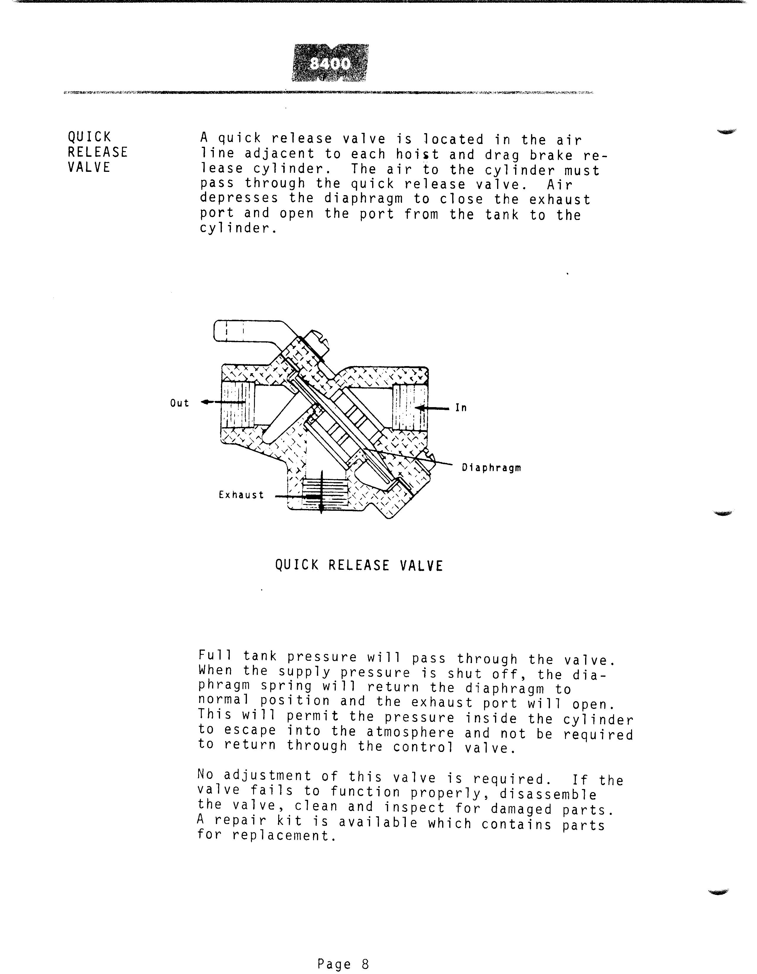
Full tank pressure will pass through the valve. When the supply pressure is shut off, the diaphragm spring will return the diaphragm to normal position and the exhaust port will open. This will permit the pressure inside the cylinder to escape into the atmosphere and not be required to return through the control valve.
No adjustment of this valve is required. If the valve fails to function properly, disassemble the valve, clean and inspect for damaged parts. A repair kit is available which contains partsfor replacement.
MAGNET VALVES The magnet valves are electrically controlled valves. The valves are non-compensating or on and off valves.
The magnet valves are normally de-engergized and closed.
A spring loaded plunger shuts off the air from the supply to the cylinder and the exhaust port from the cylinder to the atmosphere is open.
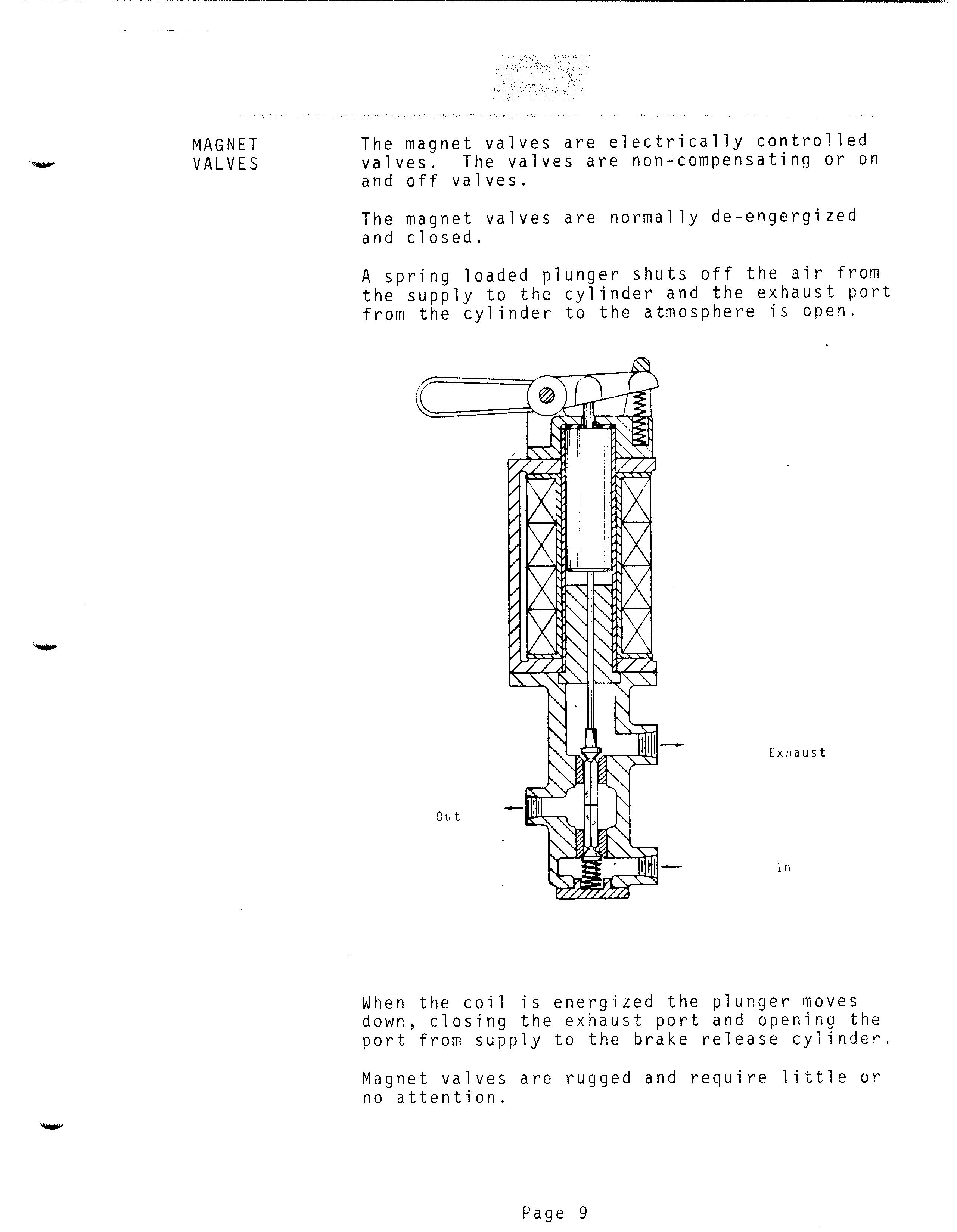
Out Exhaust
In
When the coil is energized the plunger moves down, closing the exhaust port and opening the port from supply to the brake release cylinder. Magnet valves are rugged and require little or no attention.