8 minute read
IV Lubdcation Instructions 1


View No. 2 shows the walking shoe partially pivoted out of the normal position. Thia may be caused by the shoe being pressed against ground of sufficient uneyenneas to force the roller toward one of the high sides of the cam (14) thus compressing the spring (11). The energy thus stored in the spring will return the ahoe to the normal position when it is lifted from the ground for the next atep. The direction and amount of swiveling depends on the direction and magnitude of ground slope or unevenness, the maximum position being when the roller (13) is stopped by the cam end plate (15).
The apring (11) requires an initial compression of 5-1/4 inches (equal to 24 turns of the adjusting acrew (10) for proper functioning of the swivel return mechan18m. This adjuatment must be made with the shoes off the ground (if the shoes are mounted on the machine), and the roller (13) centered on the cam (14). U the shoes are mounted on the machine, back off the adjusting screw till the apring 18 juat free (or if the shoes are being assembled, tighten the adjusting screw till the spring just ceases being free) then tighten the adjusting screw exactly Z4 full turns. A paint spot or a punch mark on the adjusting screw head will aid in counting the full turns of the adjusting screw. Never tighten the spring more than shown above, since the shoe must be capable of swiveling to the limit of the cam end plate (13) without any interference within the return mechanism.
When propelling the machine, the operator must be sure that the ground over which the machine is to trayel is fairly level and that the shoes or do not rest on any sharp obstructions. The machine should not be propelled along the aide of a steep hill where there is considerable danger of slipping. U posalble, ground over which the machine is walking should be such that both ahoes make contact with the ground at approximately the same time. When the machine reachea its digging position, the operator must be certain that the machine does not set on top of a small knoll, as this will cause the machine to rock while dig-" ging. It is very dellrable that the shoes when making contact with the ground haye bearing their entire length in order to prevent excessive strains. When the ground is extremely uneven -a dozer may be required to push large rocks out of the way, and level the ground. Filling may be done by dumping some of the spoll in the line of travel and leveling with the dozer.
SWING LOCK BRAKE (CI-58Z)
The swing lock brake used for Marion 7400 Electric Dragline is spring set, air released, and electrically controlled through a magnet valve.
Caution: This brake is intended only to hold the machine when not operating and should not be used to stop the machine when rotating. The brake must be released before the machine is operated.
PROPEL BRAKE (CI-587)
The propel is the band type and is spring set, air released, and with electric control using a magnet valve. The operation and adjustments are fully explained in CI-587.
SW9NG BRAKE -TYPES 5323, 5561, 1400 • 1800
(ALSO TYPE 5560 WITH VERTICAL SWING 11010" SPRING SET, AIR RELEASED, ELECTRIC CONTROL USING MMNET VALVE
To RELEASE
SKETCH SHOWS BRAKE IN SET POSITION
OPERATOR TURNS SWITCH TO ·OFF-, OPENING MAGNET VALVE AIR TO ENTER CYLINDER I, COMPRESS I NG SPR. NQ Sl AND rORCING PISTON ROO 3 10 MOVE OUT PISION
ROO IS 8USHED AND IS CONNECTED TO TWO LEVER BARS 4 ON THE OUTSJDE, AND TO CLEVIS WHICH
IS ON THr IN-
SIDE, BY A BOLTe CLEVIS
IS CONNECTED TO CLEvl S 6 BY ROO 7 HAVING R. H. AND L.H.
THREADS. 6 is
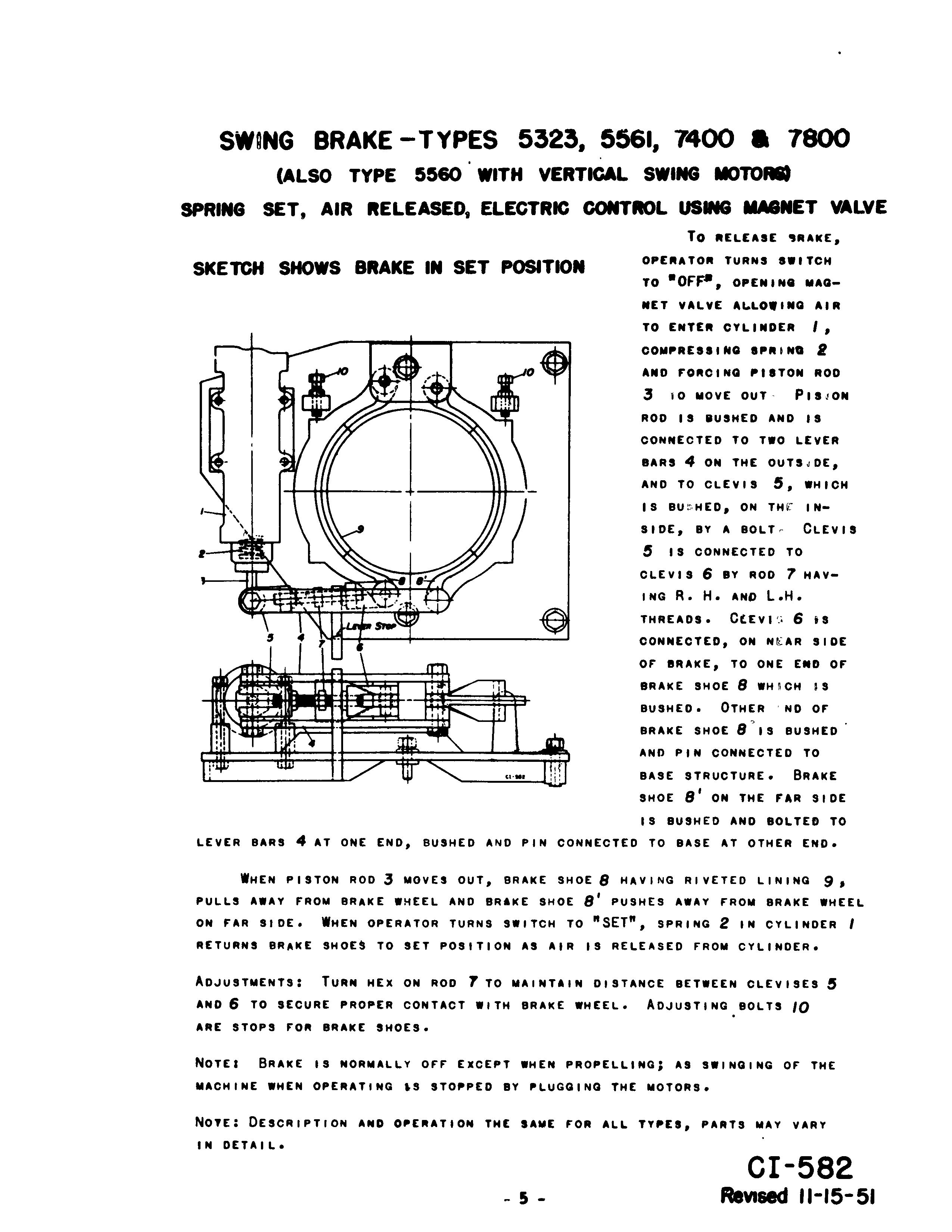
CONNECTED, ON SIDE or BRAKE, TO ONE END or BRAKE SHOE 8 WHnCH IS
BUSHED. OTHER NO or
BRAKE SHOE 8"IS BUSHED
AND PIN CONNECTED TO
BASE STRUCTURE. BRAKE
SHOE 8' ON THE rAR SIDE
IS BUSHED AND BOLTED TO LEVER BARS 4 AT ONE END, BUSHED AND PIN CONNECTED TO BASE AT OTHER END.
WHEN PISTON ROO 3 MOVES OUT, BRAKE SHOE 8 HAV I NG RiVETED LIN I NG 9, PULLS AWAY rROM BRAKE WHEEL AND BRAKE SHOE 8' PUSHES AWAY rROM BRAKE WHEEL ON rAR SIDE. WHEN OPERATOR TURNS SWITCH TO "SET", SPRING 2 IN CYLINDER RETURNS BRAKE SHOES TO SET POSITION AS AIR IS RELEASED rROM CYLINDER.
TURN HEx ON ROO 7 TO MAINTAIN DISTANCE BETWEEN CLEViSES AND 6 TO SECURE PROPER CONTACT WITH BRAKE WHEEL. BOLTS 10 ARE STOPS rOR BRAKE SHOES.
NOTE' BRAKE IS NORMALLY orr EXCEPT WHEN PROPELLING; AS SWINGING or THE MACHINE WHEN OPERATING'S STOPPED BY PLUGGING THE MOTORS.
NOYE: DESCRIPTION AND OPERATION THE SAME rOR ALL TYPES, PARTS MAY VARY IN DETAIL.
PROPEL BRAKE (BAND TYPE) 7400 a 7800
SPRING SET AIR RELEASED, ELECTRICAL CONTROL USING MAGNET VALVE ONE USED ON 7400-TWO ON 7800 SKETCH SHOWS BRAKE IN SET POSITION
To RELEASE BRAKE OPERATOR SWITCH
-----Hil---
."N'

MOVING IN. ALLOWING AIR TO ENTER THROUGH MAGNET VALVE INTO RAM CYLINDER I COMPRESSING SPRING THERE IN, AND PUSHING PISTON ROD 2 OUT, WHICH IS PIN CONNECTED TO LEvER CRANK 3. LEVER CRANK 3 HAS A FULCRUM PO I NT A, BE I NG PIN CONNECTED TO BOSSEs ON BRACKET AT THAT POINT, OTHER END OF CRANK LEVER 3 II PIN CONNECTED TO LINKS 4 WH' CH ARE PIN CONNECTED TO LEVER ARM 5; LEVER ARM 5 HAS A FULCRUM POINT B, BEING PIN CONNECTED TO BOSSES ON BRACKET AT THAT POINT, AND OTHER CONNECTION IS TO LUG 6 ON THE LiVE END OF BRAKE BAND. DEAD END OF BAND 7 IS PIN
CONNECTED TO BOSS ON BRACKET. BAND IS IN TWO PARTS 8, 9, EACH HAVING wOvEN LINING RIVETED ON, AND CONNECTED TOGETHER WITH BARS. BAND IS PROVIDED WITH TWO SPRING LIFTERS 10 ANCHORED TO THE BAND, A'D TEND TO PULL THE BAND AWAY FROM THE BREAK WHEEL, AS THE RESSION SPRINGS IN 10 ONLY OUT, DUE TO BAND LI FTER SUPPORTS II WHICH ltREVENTS THE
WHIN
2MOVEI OUT, LEVER CRANK 3 MOVES AND FULCRUMI AIOUT A WHICH II CONNECTING LINKI 4 CAUSE LEvER 5 TO MOVE, WHICH AIOUT 8, THUI I NG BAND AwAY FROM WHEEL, AI DID BY I NG LI 10. WHEN AIRII I
IN CYLINDER BAND TO THE lET
ADJUITMINT.. NUTI ON •. IF'T£RS 10 TO CO",jI,UIS ADJUITING 10LT 12 WITH HAND AND L. HAND THREADS IETwlEN LUG 6 AND LIVE IND 0' lAND, 0' THI· LINING. ADJUSTING NUT ON I TO
NOTII WHIILS THI DRAG IHA'T. THI IHA'T II IY ltlNIONI
ON THI IHAFT, WHIN THI
A LIMIT IWITCH .1 THAT MAKII IT IN8AGID IT ltOllTIVI JAW CLUTCHEI.
TO UNLIII
CLUTCHII INGAGED. THI
WHILI MAOMINI II DI80lN8 UIED TO HOLD THE IHOll 0" THI
Tile boom boist brake is the band type and is spring set and manually released. The operation and adjustments of this brake are explained in CI-589.
HOIST OR DRAG CHECK BRAKE (CI-590)
The hoist and drag check brakes are equipped with air operated brake bands. Each of these bands has a separate and independent control system. The adjustments and operations of these brakes are fully explained in CI-590.
PROPEL CLUTCH (L p. 288)
This is a jaw type clutcl1 on the left end of the drag drum shaft and is au engaged and spring disengaged. The sprina (1) should be compre8sed by the adjusting nuts (2) sufficiently to assure prompt and complete disengagement of the clutch when the air is released from the ram cylinder.
Caution The spring should not be initially compressed 80 much that it will be compressed solid before the clutch is fully engaged. The stop screw (3) should be set to stop the shifter yoke (4) at one half to three quarters inch after full disengagement. Note: The stop screw must alway8 be kept properly adjusted so that the ends of tlle clutch Jaws will not strike one another while the drag drum shaft is turning.
When setting the poppet valve adjus ing screw. care should he exercised since only 3/16 inch travel is reqUlred to open the poppet valve and over travel may damage the valve. The adjusting screw should be set 80 that the valve will be full open when the propel clutch is fully engaged, This poppet valve will release the propel brake when the propel clutch 18 engaged. and will set the propel brake when the propel clutch is diseniaaed if the propel brake control is at "Off"
HOIST AND DRAG CLU CHES (L. p. 189)
These clutches are the same except for s ,ze and will be discussed together. The clutches are air set and spring released. When air is adm'tted into the air cylinder (1). the crank pin (2) rotates. Lever arm 3) and link (4) CQnnectIJ the crank pin and the air cyhnder. Thia action tightens the frIction band (5) en the housing (6) cau8ina the drum to turn. When air is exhausted from tae air cylinder. the spring (7) will return the band to the released position. The band lifter springs lift and hold Ute band off the clutch housing when the band is released
Acijustment of the frictien clutches is accomplished by means of an eye bolt (9). Tae bands should he adjusted so that they will not require all the air cylinder travel to 'set them. aIlci atill will not slip during the meat severe service. At the same time, the eye. bolt muat be set so that the friction bands will be free and not drag on the clutch housing in the released position The spring (7) should be adjustei by means of the adjusting nut (10) 80 taat the friction band will be pr(tmptly and fully released from the housing when the air is exhausted frem the air cylinder. This sprina s.ould not be adjusted tighter thatl necessary to acceJl1.plish its purpose since the power required to compress the spring will reduce tlle power availahle to aet the friction banel.