14 minute read
Turn on AUX circuit breaker (CBR


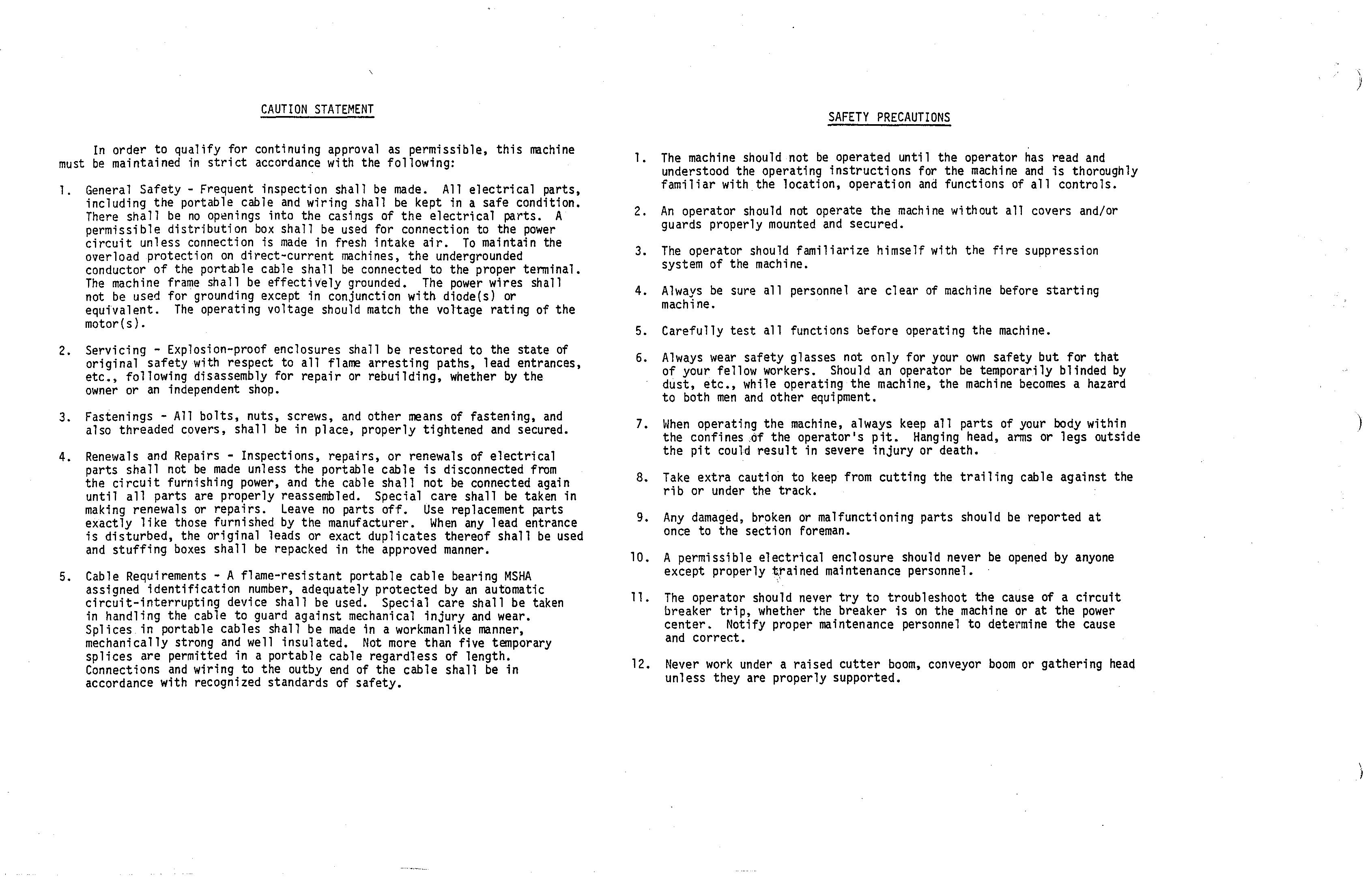
CAUTION STATEMENT CAUTION STATEMENT
In order to qualify for continuing In order to qualify for continuing approval as permissible, this machine approval as permissible, this machine must be maintained in strict accordance with the following: must be maintained in strict accordance with the following: 1. General Safety - Frequent inspection shall be made. All electrical parts, 1. General Safety - Frequent inspection shall be made. All electrical parts, including the portable cable and wiring shall be kept in a safe condition. including the portable cable and wiring shall be kept in a safe condition.
There shall be There shall be no openings no oPenings into the casings of the electrical parts. A into the casings of the electrical parts. A permissible distribution box shall be used for connection to the power permissible distribution box shall be used for connection to the power circuit unless connection is made in fresh intake air. To maintain the circuit unless connection is made in fresh intake air. To maintain the overload protection on direct-current machines, the undergrounded overload protection on direct-current machines, the undergrounded conductor of the portable cable shall be connected to the proper terminal. of the portable cable shall be connected to the proper terminal.
The machine frame shall be effectively grounded. The power wires shall The mach1ne frame shall be effectively grounded. The power wires shall not be used for grounding except in conjunction with diode(s) or not be used for grounding except in conjunction with diode(s) or equivalent. The operating voltage should match the voltage rating of the equivalent. The operating voltage should match the vOltage rating of the motor(s). motor(s). 2. Servicing - Explosion-proof enclosures shall be restored to the state of 2. Servicing - Explosion-proof enclosures shall be restored to the state of original safety with respect to all flame arresting paths, lead entrances, original safety with respect to all flame arresting paths, lead entrances, etc., following disassembly for repair or rebuilding, whether by the etc., following disassembly for repair or rebuilding, whether by the owner or an independent shop. owner or an independent shop. 3. Fastenings - All bolts, nuts, screws, and other means of fastening, and 3. Fastenings - All bolts, nuts, s:rews, and other means of fastening, and also threaded covers, shall be in place, properly tightened and secured. also threaded covers, shall be 1n place, properly tightened and secured. 4. Renewals and Repairs - Inspections, repairs, or renewals of electrical 4. Renewals and Repairs - Inspections, repairs, or renewals of electrical parts shall not be made unless the portable cable is disconnected from parts shall not be made unless the portable cable is disconnected from the circuit furnishing power, and the cable shall not be connected again the circuit furnishing power, and the cable shall not be connected again until all parts are properly reassembled. Special care shall be taken in until all parts are properly reassembled. Special care shall be taken in making renewals or repairs. Leave no parts off. Use replacement parts making renewals or repairs. Leave no parts off. Use replacement parts exactly like those furnished by the manufacturer. When any lead entrance like those by the manufacturer. When any lead entrance is disturbed, the original leads or exact duplicates thereof shall be used 1S dlsturbed, the orlglna1 leads or exact duplicates thereof shall be used and stuffing boxes shall be repacked in the approved manner. and stuffing boxes shall be repacked in the approved manner. 5. Cable Requirements - A flame-resistant portable cable bearing MSHA 5. Cable Requirements -A flame-resistant portable cable bearing MSHA assigned identification number, adequately protected by an automatic adequately protected by an automatic circuit-interrupting device shall be used. Special care shall be taken c1rcult-lnterruptlng devlce shall be used. Special care shall be taken in handling the cable to guard against mechanical injury and wear. in handling the cable to guard against mechanical injury and wear.
Splices in portable cables shall be made in a workmanlike manner, Splices in portable cables shall be made in a workmanlike manner mechanically strong and well insulated. Not more than five temporary mechanically strong and well insulated. Not more than five splices are permitted in a portable cable regardless of length. splices are permitted in a portable cable regardless of length.
Connections and wiring to the outby end of the cable shall be in Connections and wiring to the outby end of the cable shall be in accordance with recognized standards of safety. accordance with recognized standards of safety. SAFETY PRECAUTIONS SAFETY PRECAUTIONS
1. The machine should not be operated until the operator has read and 1. The machine should not be operated until the operator has read and understood the operating instructions for the machine and is thoroughly understood the operating instructions for the machine and is thoroughly familiar with the location, operation and functions of all controls. familiar with the location, operation and functions of all controls. 2. An operator should not operate the machine without all covers and/or 2. An operator should not operate the machine without all covers and/or guards properly mounted and secured. guards properly mounted and secured. 3. The operator should familiarize himself with the fire suppression 3. The operator should familiarize himself with the fire suppression system of the machine. system of the machine. 4. Always be sure all personnel are clear of machine before starting 4. Always be sure all personnel are clear of machine before starting machine. machine. 5. Carefully test all functions before operating the machine. 5. Carefully test all functions before operating the machine. 6. Always wear safety glasses not only for your own safety but for that 6. Always wear safety glasses not only for your own safety but for that of your fellow workers. Should an operator be temporarily blinded by of your fellow workers. Should an operator be temporarily b1 inded by dust, etc., while operating the machine, the machine becomes a hazard dust, etc., while operating the machine, the machine becomes a hazard to both men and other equipment. to both men and other equipment. 7. When operating the machine, always keep all parts of your body within 7. vlhen operating the machine, always keep all parts of your body within the confines of the operator's pit. Hanging head, arms or legs outside the confines.clf the operator's pit. Hanging head, arms or legs outside the pit could result in severe injury or death. the pit could result in severe injury or death. 8. Take extra caution to keep from cutting the trailing cable against the 8. Take extra caution to keep from cutting the trailing cable against the rib or under the track. rib or under the track. 9. Any damaged, broken or malfunctioning parts should be reported at once to the section Foreman. 10. A permissible electrical enclosure should never be opened by anyone except properly trained maintenance personnel.
10. A permissible electrical enclosure should never be opened by anyone except properly ned mai ntenance personnel. 11. The operator should never try to troubleshoot the cause of a circuit 11. The operator should never try to troubleshoot the cause of a circuit breaker trip, whether the breaker is on the machine or at the power breaker trip, whether the breaker is on the machine or at the power center. Notify proper maintenance personnel to determine the cause center. Noti fy proper maintenance personnel to dete'tmi ne the cause and correct. and correct.
12. Never work under a raised cutter boom, conveyor boom or gathering head 12. Never work under a raised cutter boom, conveyor boom or gathering head unless they are properly supported. unless they are properly supported.
RECOMMENDED STEPS TO FOLLOW WHEN OPERATING THE MINER RECOMMENDED STEPS TO FOLLOW WHEN OPERATING THE MINER
(Individual mines may require different cycles of operation.) (Individual mines may require different cycles of operation.)
STEP STEP OPERATING PROCEDURE OPERATING PROCEDURE
1. Make sure that everyone is clear of the machine and all valves, breakers 1. and switches are in the neutral or off position. 2. Make sure proper voltage is being supplied to the machine. 2. 3. Make sure water is being supplied to the machine. 3. 4. Turn on main circuit breaker. 4. 5. Turn on control circuit breakers. 5. 6. Turn on area lights. 6. 7. Select and turn on control valve for directional water spray. 7. 8. Turn on headlights. 9. Start pump motor. 8. 9. 10. Raise or lower conveyor and cutter boom for adequate clearance and 10. visibility. 11. Put gathering head in float position. For maximum cleanup efficiency, 11. the gathering head should rest against the mine floor and be free to float. 12. Tram machine to the face until cutterhead just touches face. 12. 13. Position the rear conveyor over the shuttle car by raising and 13. swinging to desired position. 14. Raise the cutter boom to the desired cutting height. 14. 15. Start the gathering head/conveyor motor. 15. 16. Activate water spray system. 16. 17. Start cutterhead motors. 18. Lower stabilizer shoe to help stabilize machine during sumping and 17. 18. shearing operation, if required. 19. Sump the cutterhead into the face by pushing tram levers forward. Tram 19. machine forward until it has advanced approximately 30" into the top of face. 20. Lower cutting head down, thus shearing the face. Do not tram during the 20. shearing cycle. 21. When head has reached bottom, release shear switch, raise stabilizer 21. shoe and tram machine backward approximately 36", thus trimming ridges and smoothing bottom. Make certain shuttle car is clear before backing miner. 22. Raise the cutterhead and repeat cycle (19 thru 22) until desired amount of face has been cut. 23. Turning crosscuts is accomplished by making a series of partial cuts until the machine can be turned to the desired angle.
Make sure that everyone is clear of the machine and all valves, breakers and switches are in the neutral or off position. Make sure proper voltage is being supplied to the machine. Make sure water is being supplied to the machine. Turn on main circuit breaker. Turn on control circuit breakers. Turn on area 1 i ghts.
Select and turn on control valve for directional water spray. Turn on headlights. pump motor.
Start the gathering head/conveyor motor.
Activate water spray system.
Start cutterhead motors. Lower stabilizer shoe to help stabilize machine during sumping and shearing operation, if required. Sump the cutterhead into the face by pushing tram levers forward. Tram machine forward until it has advanced approximately 30" into the top of face. Lower cutting head down, thus shearing the face. Do not tram during the shearing cycle. When head has reached bottom, release shear switch, raise stabilizer shoe and tram machi ne backward approximately 36", thus trimming ridges and smoothing bottom. Make certain shuttle car is clear before backing miner. 22. Raise the cutterhead and repeat cycle (19 thru 22) until desired amount of f ace has been cut. 23. Turning crosscuts is accomplished by making a series ·of partial cuts until the machine can be turned to the desired angle. IMPORTANT: UNDERSTAND AND OBSERVE ALL CAUTIONS AND WARNINGS IMPORTANT: UNDERSTAND AND OBSERVE ALL CAUTIONS AND WARNINGS
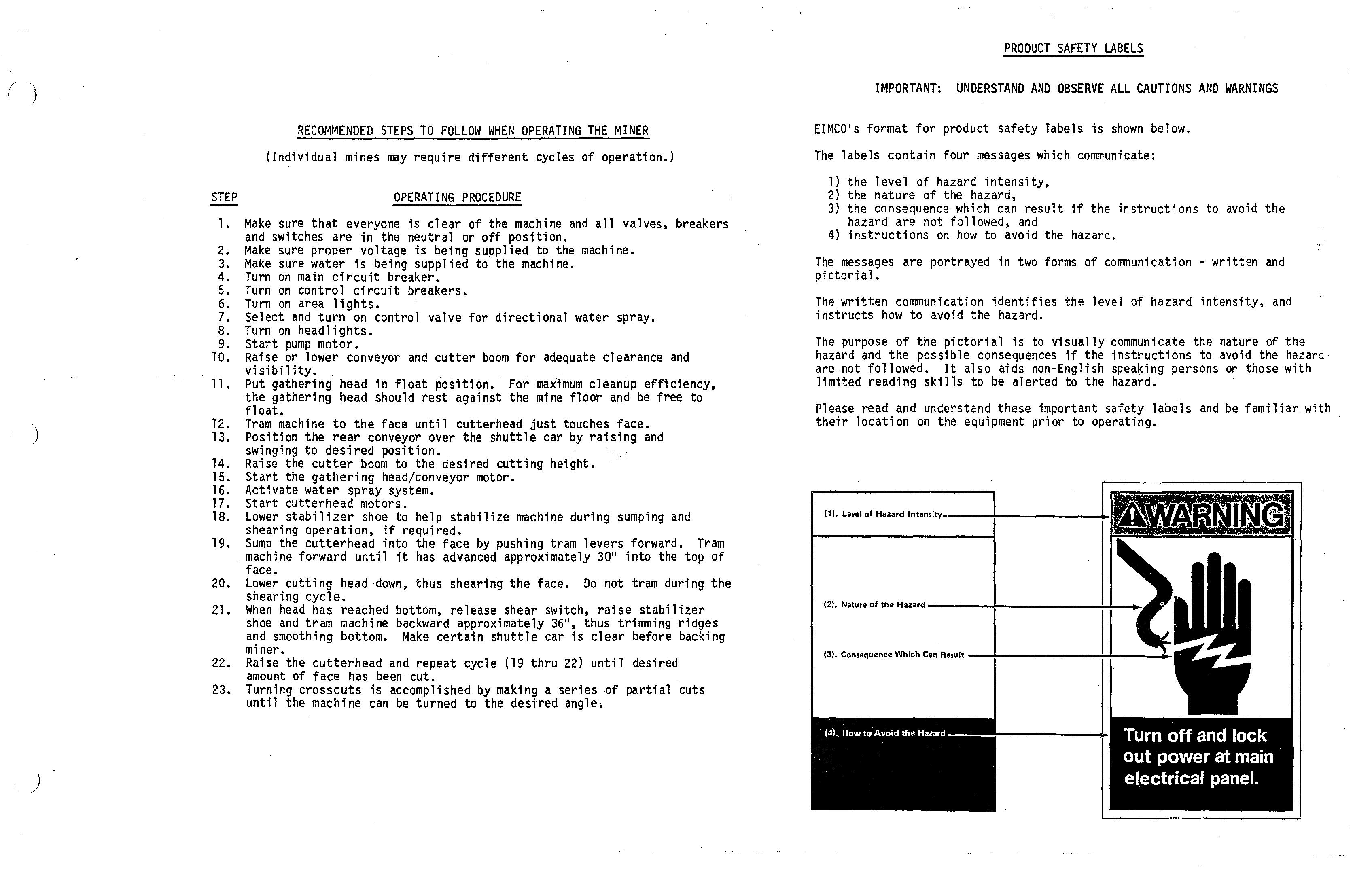
EIMCO's format for product safety labels is shown below. EIMCO's format for product safety labels is shown below. The labels contain four messages which communicate: The labels contain four messages which communicate: 1) the level of hazard intensity, 1) the level of hazard intensity, 2) the nature of the hazard, 2) the nature of the hazard, 3) the consequence which can result if the instructions to avoid the hazard are not followed, and 3) the consequence which can result if the instructions to avoid the hazard are not followed, and 4) 4) instructions on how to instructions on how to avoid the hazard. avoid the hazard. The messages are portrayed in two pictorial. The messages are portrayed in two pictorial. forms of communication - forms of communication - written written and and The written communication identifies the level of hazard intensity, and instructs how to avoid the hazard. The written communication identifies the level of hazard intensity, and instructs how to avoid the hazard.
The purpose of the pictorial is to visually communicate the nature of the hazard and the possible consequences if the instructions to avoid the hazard are not followed. It also aids non-English speaking persons or those with limited reading skills to be alerted to the hazard. The purpose of the pictorial is to visually communicate the nature of the hazard and the possible consequences if the instructions to avoid the hazard are not followed. It also aids non-English speaking persons or those with limited reading skills to be alerted to the hazard. Please read and understand these important safety labels and be familiar with their location on the equipment prior to operating. Please read and understand these important safety labels and be familiar with their location on the equipment prior to operating.
(11. Level of Hazard Int.'''ity ___ +______ +
(2). (21. Nature of the Hazard Nature of the Hazard ____ +______
(3). Consequence Which Can Result (3). Consequence Which Can Result --+-------!--1---.......
(4). How to Avoid the Hazard Turn off and lock out power at main electrical panel
INDEX INDEX
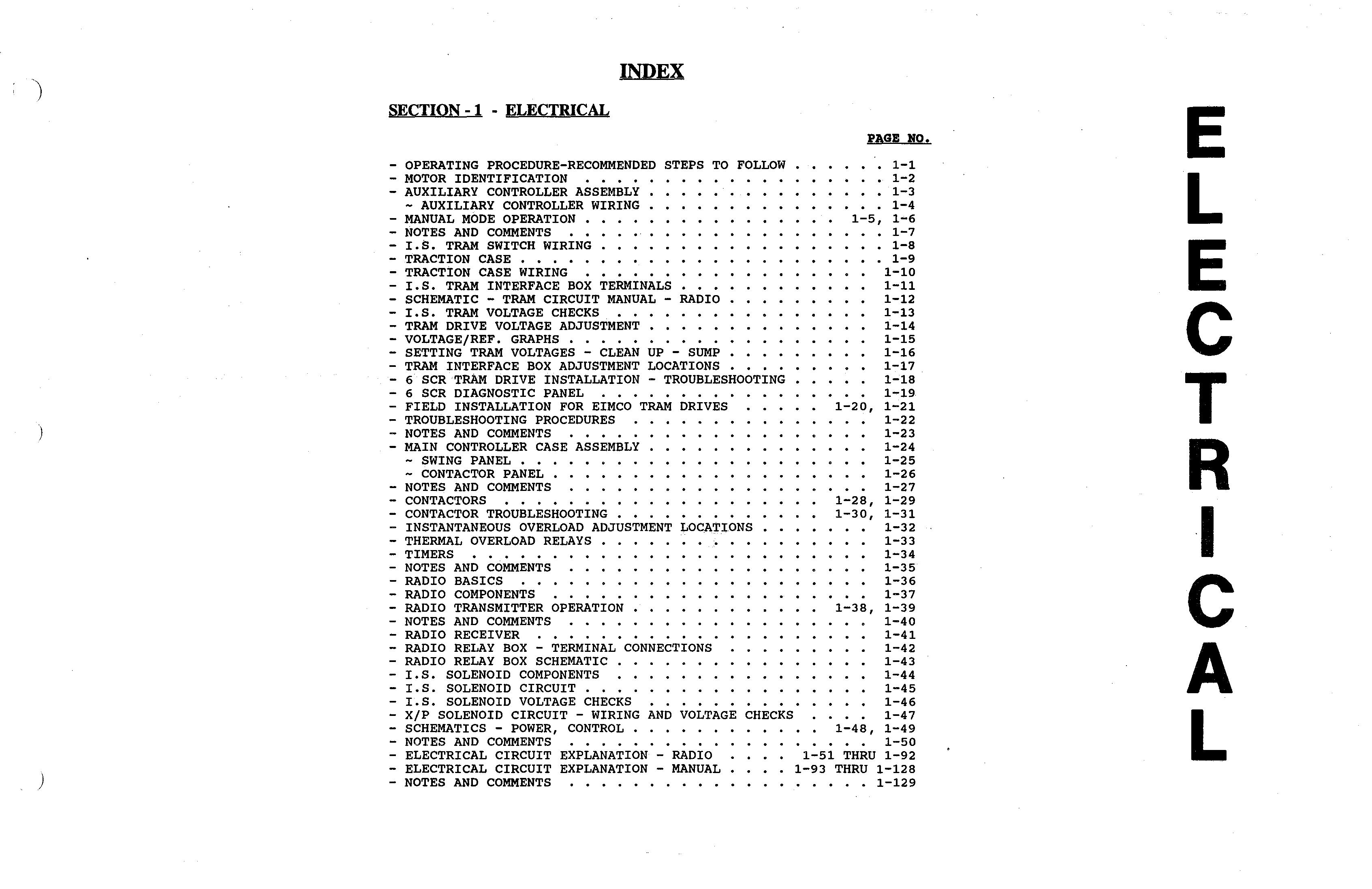
SECTION -1 - ELECTRICAL SECTION -1 - ELECTRICAL
PAGE NO. PAGE NO.
- OPERATING PROCEDURE-RECOMMENDED STEPS TO FOLLOW - OPERATING PROCEDURE-RECOMMENDED STEPS TO FOLLOW 1-1 - MOTOR IDENTIFICATION - MOTOR IDENTIFICATION • • • • 1-2 - AUXILIARY CONTROLLER ASSEMBLY - AUXILIARY CONTROLLER ASSEMBLY 1-3 - AUXILIARY CONTROLLER WIRING - AUXILIARY CONTROLLER WIRING 1-4 - MANUAL MODE OPERATION - MANUAL MODE OPERATION • 1-5, 1-6 - NOTES AND COMMENTS - NOTES AND COMMENTS 1-7 - I.S. TRAM SWITCH WIRING I.S. TRAM SWITCH WIRING 1-8 - TRACTION CASE - TRACTION CASE • • . • • 1-9 - TRACTION CASE WIRING - TRACTION CASE WIRING 1-10 - I.S. TRAM INTERFACE BOX TERMINALS - I.S. TRAM INTERFACE BOX TERMINALS 1-11 - SCHEMATIC - TRAM CIRCUIT MANUAL - RADIO - SCHEMATIC - TRAM CIRCUIT MANUAL - RADIO 1-12 - I.S. TRAM VOLTAGE CHECKS - I.S. TRAM VOLTAGE CHECKS .•• 1-13 - TRAM DRIVE VOLTAGE ADJUSTMENT - TRAM DRIVE VOLTAGE ADJUSTMENT •.• 1-14 - VOLTAGE/REF. GRAPHS - VOLTAGE/REF. GRAPHS . . . ., •• . 1-15 - SETTING TRAM VOLTAGES - CLEAN UP - SUMP - SETTING TRAM VOLTAGES - CLEAN UP - SUMP 1-16 - TRAM INTERFACE BOX ADJUSTMENT LOCATIONS - TRAM INTERFACE BOX ADJUSTMENT LOCATIONS 1-17 - 6 SCR TRAM DRIVE INSTALLATION - TROUBLESHOOTING -6 SCRTRAM DRIVE INSTALLATION - TROUBLESHOOTING 1-18 - 6 SCR DIAGNOSTIC PANEL -6 SCR DIAGNOSTIC PANEL . • • . • • . • • 1-19 - FIELD INSTALLATION FOR EIMCO TRAM DRIVES - FIELD INSTALLATION FOR EIMCO TRAM DRIVES 1-20, 1-21 - TROUBLESHOOTING PROCEDURES - TROUBLESHOOTING PROCEDURES 1-22 - NOTES AND COMMENTS - NOTES AND COMMENTS •• • • . 1-23 - MAIN CONTROLLER CASE ASSEMBLY - MAIN CONTROLLER CASE ASSEMBLY 1-24 - SWING PANEL - SWING PANEL • • . 1-25 - CONTACTOR PANEL - CONTACTOR PANEL • . • • 1-26 - NOTES AND COMMENTS - NOTES AND COMMENTS • . . 1-27 - CONTACTORS - CONTACTORS • • . • . . • 1-28, 1-29 - CONTACTOR TROUBLESHOOTING - CONTACTOR TROUBLESHOOTING 1-30, 1-31 - INSTANTANEOUS OVERLOAD ADJUSTMENT LOCATIONS - INSTANTANEOUS OVERLOAD ADJUSTMENT LOC.ATIONS 1-32 - THERMAL OVERLOAD RELAYS - THERMAL OVERLOAD RELAYS 1-33 - TIMERS - TIMERS • • • • • . 1-34 - NOTES AND COMMENTS - NOTES AND COMMENTS 1-35 - RADIO BASICS - RADIO BASICS . • . • . 1-36 - RADIO COMPONENTS - RADIO COMPONENTS 1-37 - RADIO TRANSMITTER OPERATION - RADIO TRANSMITTER OPERATION 1-38, 1-39 - NOTES AND COMMENTS - NOTES AND COMMENTS . . . • 1-40 - RADIO RECEIVER - RADIO RECEIVER . • • . . • 1-41 - RADIO RELAY BOX - TERMINAL CONNECTIONS - RADIO RELAY BOX - TERMINAL CONNECTIONS 1-42 - RADIO RELAY BOX SCHEMATIC - RADIO RELAY BOX SCHEMATIC . . 1-43 - I.S. SOLENOID COMPONENTS - I.S. SOLENOID COMPONENTS ••.••.. 1-44 - I.S. SOLENOID CIRCUIT I.S. SOLENOID CIRCUIT. . •. . .• 1-45 - I.S. SOLENOID VOLTAGE CHECKS - I.S. SOLENOID VOLTAGE CHECKS .•. 1-46 - X/P SOLENOID CIRCUIT - WIRING AND VOLTAGE CHECKS - X/P SOLENOID CIRCUIT - WIRING AND VOLTAGE CHECKS 1-47 - SCHEMATICS - POWER, CONTROL - SCHEMATICS - POWER, CONTROL • •.. 1-48, 1-49 - NOTES AND COMMENTS - NOTES AND COMMENTS . • . ., ... 1-50 - ELECTRICAL CIRCUIT EXPLANATION - RADIO . - ELECTRICAL CIRCUIT EXPLANATION - RADIO 1-51 THRU 1-92 - ELECTRICAL CIRCUIT EXPLANATION - MANUAL . - ELECTRICAL CIRCUIT EXPLANATION - MANUAL . 1-93 THRU 1-128 - NOTES AND COMMENTS - NOTES AND COMMENTS . • • . • • . . • . 1-129
1-1 1-2 1-3 1-4 1-5, 1-6 1-7 1-8 1-9 1-10 1-11 1-12 1-13 1-14 1-15 1-16 1-17 1-18 1-19 1-20, 1-21 1-22 1-23 1-24 1-25 1-26 1-27 1-28, 1-29 1-30, 1-31 1-32 1-33 1-34 1-35 1-36 1-37 1-38, 1-39 1-40 1-41 1-42 1-43 1-44 1-45 1-46 1-47 1-48, 1-49 • •. 1-50 1-51 THRU 1-92 1-93 THRU 1-128 . . • . . 1-129