7 minute read
Accelerator Pedal Position Sensors


6.0 Accelerator Pedal Position Sensors
The accelerator pedal position sensor converts the mechanical accelerator pedal position into an electrical signal for the ECM.Caterpillar requires one of the sensors described in this document for use with an accelerator pedal.
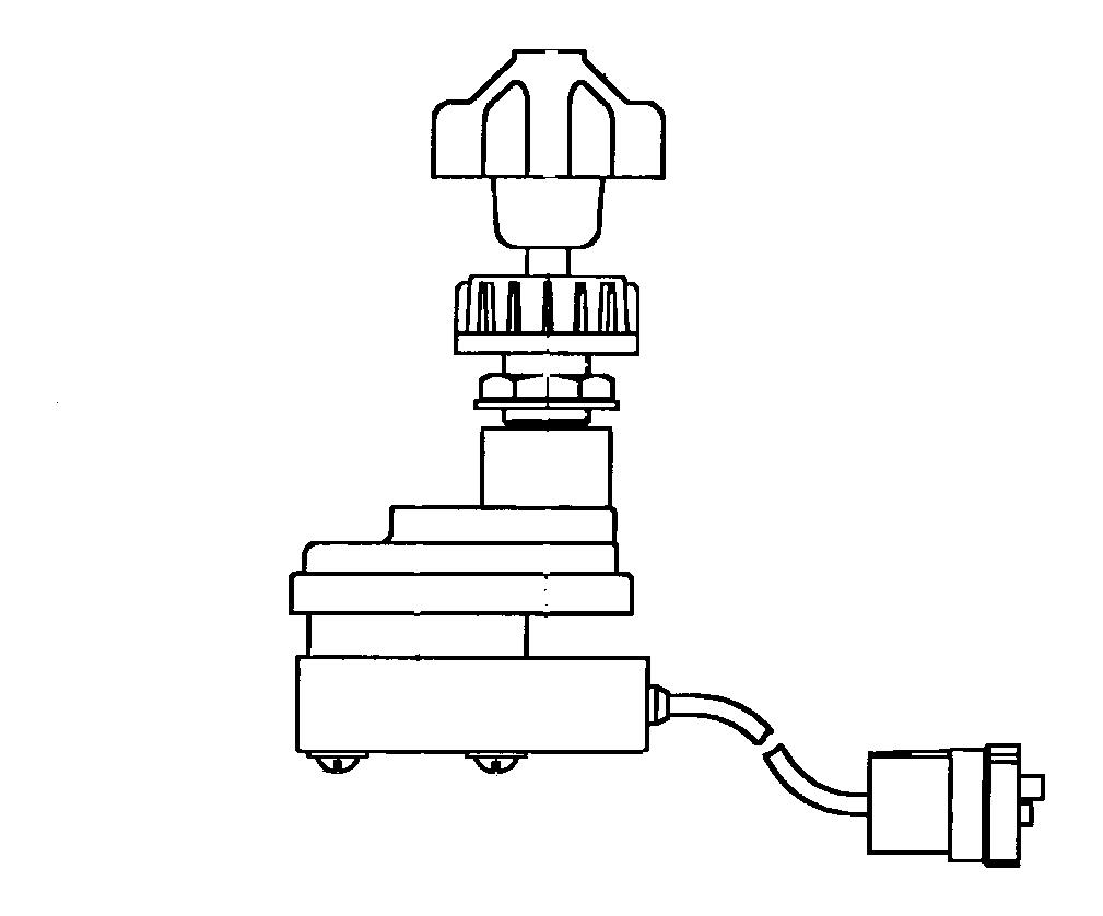
Figure 20 - 204-7949 or 204-7950 Accelerator Pedal Position Sensor with Deutsch DT Connector
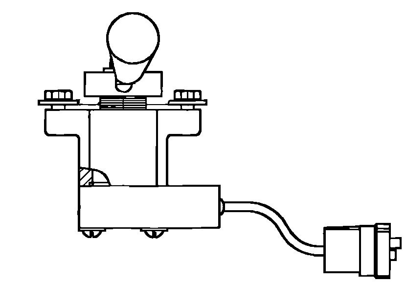
Figure 21 - 204-7951 Accelerator Pedal Position Sensor with Packard Connector The accelerator pedal position sensor is designed to comply with FMVSS124 (Federal Motor Vehicle Safety Standard 124).The sensor also meets the SAE J1843 Recommended Practice. 204-7949, 204-7950, and the 204-7951sensors mount directly to the accelerator pedal.This eliminates the need foraccelerator pedal linkages and OEM adjustments.These sensors are designed to operate from the ECM + 8V supply.The 204-7949 (32 inch [81 cm] harness with Deutsch connector), 204-7950 (6 inch [15 cm] harness with Deutsch connector), and the 204-7951 (6 inch [15 cm] harness with Packard connector) use the same sensor but have different connectors or pigtail lengths as described.
6.1 Accelerator Pedal Position Sensor Electrical Specifications
The sensor output is a constant frequency signal whose pulse width (duty cycle) varies with accelerator pedal position.The Pulse Width Modulated (PWM) signal is expressed as a percentage (percent duty cycle) as showninFigure 21.
25% Duty Cycle
75% Duty Cycle
Figure 22 - Example PWM Signals
6.2 Accelerator Pedal Position Sensor Duty Cycle
The Accelerator Pedal Position Sensor (APP Sensor) mounts directly to the pedal and should not be adjusted by the OEM.The OEM must insure that pedals supplied by the pedal manufacturer meet the following specification forsensor output duty cycle.
The pedal assembly should also conform to SAE J1843. NOTE: The ECM automatically calibrates (auto-cal) new duty cycle values for the Low Idle and High Idle throttlepositions each time the ECM is powered.The ECM initially assumes 22 percent duty cycle is low idle and75percent duty cycle is high idle.As a result, the Throttle Position Status may reach 100 percent well before the accelerator pedal is fully depressed.This is normal operation and will continue until the ECM learns the limits ofthelow and high idle stops.Following some cycling of the accelerator pedal from the low to the high idle positions, the ECM will adjust its calibration automatically, provided the high idle stop position is within the 75to90percent duty cycle range, and the low idle is in the 10 to 22 percent duty cycle range. During normal operation it may initially require more accelerator pedal movement for the Throttle Position Status toincrease above 3 percent (low idle) and the Throttle Position Status may reach the 100 percent (high idle) valueprior to the limit of the high idle position.This is done to ensure the throttle reaches these two critical points for engine operation.As the ECM learns the physical limits, the range is expanded as long as it is within the values specified above.If the Duty Cycle value goes outside of the expected range, a diagnostic code will be activated.
Accelerator pedal position Duty Cycle Low Idle 10% - 20% High Idle 75% - 90%
NOTE: There is no direct correlation between the Sensor Duty Cycle value and a Desired Engine RPM.For example, it is not possible to input a 50% duty cycle value and expect the engine to operate at 1800 rpm. Thisisdue to the Auto-Cal function which constantly calibrates for the low and high idle stop positions.
6.3 ECM +8V Cab Accelerator Pedal Position Sensor Supply
This sensor supply is designed to provide power for connection to OEM installed Cab Accelerator Pedal Position Sensor (+8V).No other vehicle components may be connected to this supply.
6.4 Accelerator Pedal Position Sensor Connections
The 204-7949 accelerator pedal position sensor is designed to operate on 8 Volts DC supplied by the ECM.The ECM supplied +8V, AP Sensor/Switch Sensor Common, and Accelerator Pedal Position wiring must be connected to the control system through an OEM harness.Current draw for the sensor is less than 40 mA. AP Sensor/Switch Sensor Common must not be connected to the vehicle cab ground.Connecting AP Sensor/ Switch Sensor Common to the vehicle cab ground can degrade control system performance.AP Sensor/Switch Sensor Common must be connected to the ECM at the OEM connector (P1 terminal-5) via a dedicated return line. Connector terminal assignments are as follows:
Sensor Terminal Assignment ECM Terminal Assignment Terminal Description Terminal A J1/P1:4 + 8 VDC Terminal B J1/P1:5 AP Sensor Common Terminal C J1/P1:66 Accelerator Pedal Position
6.5 Accelerator Pedal Position Sensor Connectors 6.5.1 Three Terminal Deutsch Mating Connector
The 204-7949 (32 inch [81 cm] harness) and 204-7950 (6 inch [15 cm] harness) Accelerator Pedal Position Sensors require a Deutsch DT06-3S-EP04 (Caterpillar part number 3E-3367) mating connector plug with aDeutsch W3S (Caterpillar part number 3E-3368) connector plug wedge.
Figure 23 - Three Terminal Accelerator Pedal Position Sensor Deutsch DT Connector
6.5.2 Deutsch Connector Wire Gauge Size
The connections may be made with #16 or #18 AWG SAE J1128 type SXL (or GXL) or equivalent wire.
Outside diameter insulation range is 2.24mm to 3.81mm (0.09 to 0.15 in.)
The 204-7951 Accelerator Pedal Position Sensor (6 inch [15 cm] harness) requires a Packard Electric Division 12110293 (Caterpillar part number 124-5641) mating connector.
Figure 24 - Three Terminal Accelerator Pedal Position Sensor Packard Electric Connector
6.5.5 Packard Electric Connector Wire Gauge Size
The connections may be made to 204-7951 with #18 AWG SAE J1128 type SXL (or GXL) or equivalent wire.
Outside diameter insulation should be 2.80mm (0.11in.).
The following table provides terminal part numbers.
Required Connector Parts
Description Usage Part Numbers Caterpillar Part Numbers 3 Terminal Plug and Seal APP Sensor Connector Deutsch DT06-3S-EP04 3E-3367 3 Terminal Plug Wedge APP Sensor Connector Deutsch W3S 3E-3368
Socket Contact #16 OR #18 AWG Wires Deutsch 0462-201-16141 8T-8730 (machined)
Socket Contact #18 AWG Wires Deutsch 1062-16-0122 115-1051 (stamped & formed) 3 Terminal Plugs APP Sensor Connectors Packard 12110293 124-5641
Socket Terminal #18/#20 AWG Wires Packard 12048074 124-5640
6.6 Accelerator Pedal Position Sensor for Remote PTO Applications
Caterpillar recommends the 161-8906 accelerator pedal position sensor for remote PTO applications.The sensor provides the same type of signal as the 204-7949, 204-7950, and the 204-7951 sensors, but requires battery voltage (12 or 24 volt systems) to operate.This Sensor must NOT be connected to the +8V supply intended fortheCab Sensor, nor can the Cab Sensor be connected to a +12 Volt supply.
Figure 25 - 161-8906 Accelerator Position Sensor with Deutsch HD Connector
6.6.1 PTO Accelerator Position Sensor Connector
The 161-8906 is supplied with a 3-terminal Deutsch HD plug connector (HD16-3-96S, Caterpillar P/N 8T-8731). Theconnecting harness will require a Deutsch HD receptacle connector (HD14-3-96P, Caterpillar P/N 8T-8732).
6.6.2 Mounting the Remote Accelerator Position Sensor
The 161-8906 Accelerator Pedal Position Sensor can be attached to either an accelerator pedal assembly (contact the vehicle OEM for parts) or a Caterpillar 107-2281 PTO Accelerator Assembly.The PTO Accelerator Assembly does not include a handle.It may be used in applications where a mechanical linkage is required.The accelerator position sensor mounts directly to the PTO Accelerator Assembly and does not require additional sensor calibration.
Figure 26
Two Remote Accelerator Pedal Position Sensor Assembly packages are available from Caterpillar that include the 161-8906 sensor and mounting hardware.The 134-0597 assembly provides the 161-8906 sensor mounted to a control arm lever.The 134-0670 assembly provides the 161-8906 sensor mounted to an adjustable dial mechanism, which can be automatically reset to the low idle position or locked into place at a specific position. NOTE: The Remote Throttle PTO Configuration requires the Remote Throttle to be returned to the Low Idle position upon engine start up, in order for Remote Throttle control to be provided.If the engine is started with the PTO Switch ON and the Remote Throttle at a position above Low Idle, the engine will be limited to Low Idle until the Throttle is cycled to the low idle position.
(Sensor Not Included)
(Handle Not Included)
134-0597 Remote Accelerator Assembly 134-0670 Remote Accelerator Assembly Figure 27
Input #8 (terminal-68) is available for use as a Remote Accelerator Input for Remote Throttle PTO applications. OEM provided and installed components required: 1) Throttle Sensor 2) Accelerator pedal or other mechanical linkage. Customer Parameter programming required: 3) PTO Configuration programmed to Remote Throttle. 4) PTO On/Off circuit
All signal requirements are identical to those outlined for 204-7949 except the 161-8906 sensor requires connection to battery voltage (12 VDC or 24 VDC) instead of the ECM supplied 8 VDC.
6.6.6 Remote Accelerator Pedal Sensor Common Connections
Three different Sensor Common terminals can be used (J1/P1:3, 5 or 18) to ground the Remote Accelerator Pedal Position Sensor to the ECM.However, Caterpillar recommends that Input J1/P1:3 remain open for aftermarket/body builder installation.