41 minute read
(Fig. 2-62:) Optional equipment


No. Element Function Symbol
165 Warning lamp Slewing motor 1 contaminated Lights up when the slewing motor is contaminated with metal particles.
166 Warning lamp Slewing motor 2 contaminated Lights up when the slewing motor is contaminated with metal particles.
167 Warning lamp free for optional
168 Warning lamp Hydraulic oil filter contaminated Lights up when the flow resistance in the filter is too high. Replace filter elements if the warning lamp fails to go out when the oil is at operating temperature.
169 Warning lamp Min. hydraulic oil level Lights up when the hydraulic oil level in the hydraulic tank is too low.
170 Warning lamp Electronic shovel control ON Lights up when the electronic shovel control is switched on.
171 Indicator light Hydraulic oil tank Lights up when one of the shut-off valves of the hydraulic oil tank is closed When the valve is closed, the electric motor cannot be started. When a shutoff valve is closed with the electric motor running, the motor is stopped.
172 Thermometer Hydraulic oil Indicates hydraulic oil temperature in hydraulic tank.
Putting The Machine Into Operation
Before daily start-up, carry out works in accordance with servicing plan T (cf. Part 3 "Inspection and servicing").
Prior to your dailiy start-up, make sure the machine has been cleaned of combustible and easily flammable substances.
Otherwise, increased fire and explosion hazard will exist.
Service station (tanklift)
The shovel is equipped with a central service station (Fig. 2-63:The service station is attached to the frame and accessible from the ground below the uppercarriage. Express couplings are provided for refilling the following consumables (fluids).
Note:
Connections used may vary depending on how the machine is equipped.
Pos. Fig. 2-63:
Fluid Express coupling for
5 Gearbox oil for pump drive gearbox (optional)
Filling and/or draining
10 Hydraulic oil tank Filling and/or draining
11 Grease for central greasing system Filling
A service vehicle is needed for filling and/or draining of the fluids.
Lowering the service station
Draw out control knob (21, Fig. 2-63:) of valve (22) with rope (25). The service station is brought down to the lower position. Turn knob (21) by 90° and engage.
Raising the service station
Disengage control knob (21) of valve (22), turn by 90° and press in. The service station is raised to the top position.
Refilling and draining
For filling in or for draining fluids, unscrew the cap of the corresponding express coupling (Fig. 2-63:).
Attach express coupling of filling hose from the service vehicle to the corresponding express coupling at the service station. Fill in or drain off fluid. Take off filling hose and refit cap on the express coupling.
Assemblies resp. reservoirs Measuring device Remarks
Pump drive gearbox Dipstick (Fig. 2-64:) Stop filling when the oil reaches the "max" mark on the dipstick (cf. Part 3, chapter "Pump drive gearboxChecking the gearbox oil level/Filling in oil").
Hydraulic oil tank Inspection glass (1, Fig. 2-65:), sign (2. Fig. 2-65: and Fig. 2-66:)
Checking the oil level: Extend the piston rods of stick and bucket cylinders halfway. Stand working equipment on the ground. Check oil level at an oil temperature of ca. 50 °C (122°F), with the electric motor stationary. Fill in oil when the oil level in the inspection glass has dropped below the "min" mark. Stop filling if the oil reaches the "max" mark on the inspection glass or the acoustic warning signal "Travel alarm" sounds (cf. chapter "Hydraulic system - Checking the hydraulic oil level / Refilling hydraulic oil").
Assemblies resp. reservoirs Measuring device Remarks
Grease container –cental lubricating system
BCS display (Fig. 2-67:) BCS display indicates a warning when the grease container is empty.
Fill in grease using express coupling (11, Fig. 2-68:).
Switch on the display system with the toggle switch (23, Fig. 2-68:). Monitoring lamp (22) lits up.
Stop filling when BCS indicates "Grease container filled". The indicator lamp (24) lights up.
On completion of filling, switch the display system off again with the toggle switch (23). Monitoring lamp (22) is off.
Battery main switch, switching on and off
When the shovel is disconnected from the medium voltage (6.3 kV) the electrical system (24V) is supplied with voltage by two batteries. With the battery main switch, the electrical system (24V) is disconnected from the batteries.
The battery main switch is located at the right side wall of the control cabinet (24V). The control cabinet (24V) is mounted in the operator's cab module beneath the operator's cab.
Switching the battery main switch on Insert switching handle into battery main switch (position "0", Fig. 2-69:) and turn it to position "I".
Switching the battery main switch off
Turn switching handle from position "I", Fig. Fig. 2-69: to position "0" and withdraw.
Electrical system (24V), switching on and off
The electrical system is switched on or off with key-switch (32, Fig. 2-70:).
Switching the electrical system (24V) on
Insert key into key-switch (32) and turn to the right.
Now all electronical assemblies of the shovel are supplied with voltage, computer systems are started. A selftest is carried out.
The Board Control System (BCS) displays current operating data as well as detected faults.
If there are no critical faults detected BCS enables starting the electric motor.
If there are critical faults or failings detected BCS disables starting the electric motor and displays corresponding explanatory text.
For more information see "Operating Instructions Board-Control-System".
Switching the electrical system (24V) off
Turn key in key-switch (32) to the left and withdraw
Switching the electric motor on and off
Before switching on the electric motor
Before switching on the electric motor, check that nobody is working on the electrical system or on the shovel itself.
Switch on the electric motor only when all these work on the shovel is finished and all persons leave the danger area.
Switch on battery main switch (see: "Battery main switch, switching on and off").
Switch on electrical system (24V) (see: "Electrical system (24V), switching on and off").
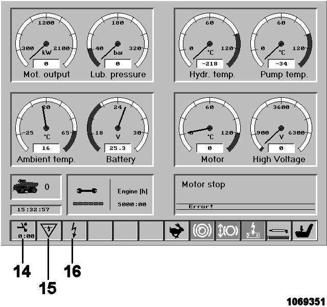
Check telltales (14 and 16, Fig. 2-71:), they must lit up in green colour.
If so, electric motor can be switched on (see: "Switching the electric motor on").
If telltales didn`t lit up in green colour, BCS has detected critical operating conditions or faults which prohibit starting the electric motor. BCS indicates this case with telltales (for instance 15, Fig. 2-71:) as well as by displaying corresponding text.
Switching the electric motor on
Actuate switch-key (51, Fig. 2-72:), the electric motor is switched on.
During starting period the electric motor heavily warm up. Therefore it is not allowed to switch it on and off at will. By means of an electronical time-out circuit (PLC) the electric motor can be switched on only three times a hour (time-out period is 30 minutes).
Switching the electric motor off
During breaks in operation and at the end of each shift, the working equipment must be lowered onto the ground.
The electric motor must NOT be switched off until the equipment is resting on the ground.
To avoid straining the vacuum contactor, the electric motor should be shut down only when load-free, i.e. without any of the hydraulic units being activated at the same time via the control valve.
Actuate switch-key (52, Fig. 2-73:). The electric motor starts running down.
Turn key in key-switch (32) counter-clockwise and withdraw.
The control voltage is switched off. The electric motor only can be switched on again, after the time-out period (30 minutes after last switching on) is over (see: "Time-out before restart", "Before switching on the electric motor" and "Switching on the electric motor").

Time-out before restart
During starting period the electric motor heavily warms up. Therefore it is not allowed to switch it on and off at will. By means of an electronical time-out circuit (PLC) the electric motor can be switched on only three times a hour (time-out period is 30 minutes).
The 30 minutes period means the time from switching on the electric motor up to the next switching on, e. g.
Electric motor is switched on, runs 20 minutes and then is switched off. Now the time-out period is 10 minutes before restart.
After running more than 30 minutes without interruption the electric motor can be switched on without any time-out period.
PLC prohibits switching on the electric motors until they are cooled down.
Monitoring lamp (14, Fig. 2-74:) on the BCS display is flashing in yellow colour until the time-out period is over. The remaining time is displayed also.
Monitoring lamp lit up in green colour when the time-out period is over and PLC enables switching on the electric motor.
Electric motor can not be switched on
If BCS prohibits switching on the electric motor the operator should check the following:
Time-out before restart period still running?
EMERGENCY STOP switch in control column unlocked?
EMERGENCY STOP switch in control cabinet (400V) unlocked?
EMERGENCY STOP pullswitch near the service station unlocked?
Servicing switch unlocked?
Monitoring lamps "6.3 kV OK" and "PHASE SEQUENCE OK" on the control cabinet (400V) and on the control column lighting? If not, the circuit breaker is switched off or the 6.3 kV voltage supply is missing.
Shut-off flaps at the hydraulik oil reservoir closed?
Check BCS display: Faults or explanatory text displayed? If so, give information to the electric maintenance personnel.
If after all of these checks the electric motor cannot be switched on the operator has to inform the specialist personnel for maintenance and service on electric shovels. Only these have the skills to work in a safe way, for trouble shooting and removing the fault.
In case of failure
If failures in the electrical systems occur, BCS displayes warnings and corresponding explanatory text
Failures in electrical systems may exclusively be removed by specialist personnel for maintenance and service on electrical systems. The following faults may be responsible: fault in high-voltage transformer
6.3 kV/ 400V/ 230V transformer overloaded. earth fault.
If BCS display shows "Overcurrent", the operator does not know if an "Earth fault" happens. In worst case the shovel may be energized. The operator must notify the electrician in charge from the shovel superstructure.
The electrician must then cut off the voltage supply from the transformer station and locate and rectify the fault.
Circuit breaker, switching on and off
By means of the circuit breaker the supplied medium voltage 6.3kV can be connected to the shovels electrical system or can be disconnected from it. The circuit breaker is installed in the control cabinet 6.3 kV (Fig. 2-75: and Fig. 2-76:).
Switching the circuit breaker on is possible only when PLC and motor protection relay enable thie function. In this case, monitoring lamp (Fig. 2-76:) lights up.
The circuit breaker is operated with an actuating lever which is stored in a fixture inside the control cabinet 6.3 kV.
Switching on the circuit breaker
Slip actuating lever (Fig. 2-77:) onto the actuating shaft of the circuit breaker. Pull locking element outwards against spring pressure.
Turn actuating lever by ca. 180°upwards (Fig. 2-77:). This tensions the cut-out spring.
Turn actuating lever (Fig. 2-78:) by 180° downwards.
This tensions the cut-in spring and the circuit breaker is switched on.
Engage locking ring.
The indicator lamps "6.3 kV OK" (1, Fig. 2-79:) and "PHASE SEQUENCE OK" (2) comes on at the control cabinet 400V and at the control column in the operator's cab. Withdraw the actuating lever and put it into its fixture.
Switching off the circuit breaker
Slip actuating lever (Fig. 2-80:) onto the actuating shaft of the circuit breaker. Pull locking element outwards against spring pressure.
Using actuating lever (Fig. 2-80:), turn actuating shaft ca. 20°clockwise. This releases the cut-out spring. The circuit breaker is switched off.
The indicator lamps "6.3 kV OK" (1, Fig. 2-79:) and "PHASE SEQUENCE OK" (2) goes out at the control cabinet 400V and at the control column in the operator's cab.
Withdraw the actuating lever and put it into its fixture.
Further detailed information is given in the attached leaflet on circuit breakers.
Motor protection relay, function
The electric motor is equipped with a motor protection relay. The relay is located in the 400 V switch cabinet (Fig. 2-81:).
The relay monitors the operating conditions of the electric motor and protects the motor against faults in the electrical system of the motor
Depending on the nature of the fault, the motor protection relay switches off the power supply of the motor via the vacuum contactor or the power supply of the machine via the switch-disconnector.
At the factory, the motor protection relay is programmed for the following functions: protection against overcurrents, protection against overloading, detection of ground faults, temperature monitoring, restart inhibit, protection against undervoltage, protection against load unbalance (failure of a phase) phase sequence monitoring, change of frequency, run-up period monitoring.
In case a severe fault of the motor system is detected in operation, the motor protection relay is activated and the electric motor shut off automatically. If the motor protection relay detects a severe fault before or during the starting sequence of the electric motor, it prevents the motor from being started. Depending on the type of fault detected, one or more LEDs on the front panel light up (9, Fig. 2-82:).
After rectification of the fault press button (7). The LED is extinguished. The motor protection relay is again operational.
For more information please refer to the the manufacturer's description.
Front panel control and monitoring elements
See Fig. 2-82:
Fig. 2-82:
1 RUN indicator (LED)
2 Display screen (provides information on states of operation)
3 Display screen navigation keys
4 Function key freely programmable (not used for this machine)
5 Control of other equipment (not used for this machine)
6 USB interface for communication with external devices (only for CGM HMS GmbH Service)

7 Reset for LEDs of item 9.
8 Cover for keypad of item 4.Functional description of the LEDs of item 9.
9 LEDs G1 – G8, on after detection of a fault: G1 – Overcurrent
G2 – Undervoltage/overvoltage
G3 – Load unbalance
G4 – Frequency change
G5 – Overload
G6 – Phase sequence fault, ground fault
G7 – Run-up monitoring, restart inhibit G8 – Emergency STOP activated
For more information please refer to the the manufacturer's description.
Warm-up procedure for electric shovels
Operator procedure during start up in extreme cold weather
After starting the electric motor check for any faults on the BCS display.
Make sure the “SERVO” switch (74, Fig. 2-85) is in the OFF position.
Use the “Boom up” (116, Fig. 2-84: backwards) or “Stick out” function (115, Fig. 2-84: forwards) to engage the hydraulic pumps. This will engage the pumps without moving the attachment.
Do so until:
- the hydraulic oil temperature reaches 10°C on the gauge and
- the PTO temperature has reached 5°C.
You can now turn ON the “SERVO” switch (74, Fig. 2-85Fig. 2-86:) and move the attachment in a slow function one at a time.
Do not extend the cylinders fully.
Swing circuit warm-up before you start digging
Make sure the attachment or bucket is on the ground.
Turn “Swing brake” switch OFF (82, Fig. 2-86:).
Turn “SERVO” switch ON (74).
Use “Swing left” or “Swing right” function (115, Fig. 2-84:) slowly. This will heat the swing hydraulic circuit quickly.
Once the swing temperature is warm you can lift the attachment and swing the shovel in a slow 360°left then right.
Air conditioner (option)
Ventilation / Heating
The air needed for ventilation and/or heating is sucked in from outside the cab by a blower and ducted to the air outlets. If necessary, the air in the cab is sucked in through the and recirculated.
The air conditioner control elements are located at the left side of the control column (Fig. 2-86:). Do not switch the air conditioner to "cooling“ when the back-up heating (optional) is on.
Control panel (Sigma)
(see Fig. 2-86:)
1 Rotary switch Selects the intensity level of the blower (3 levels).
2 Rotary switch Selects the desired control function (heating, cooling, ventilation, defrosting).
3 Thermostat Sets the desired temperature inside the cab.
TRAVELLING THE MACHINE Travelling, Safety Instructions
Have the attachment raised only so far as to permit the machine to be driven under overhead power lines without any risk. Close the cab door.
If the machine is fitted with a safety belt for the operator, fasten the belt.
If the superstructure is turned by more than 90° from the BASIC POSITION, the shovel travels in the opposite direction to that selected.
If the position of the superstructure in relation to the undercarriage is not exactly known, touch the accelerator
Lightly to see which direction the machine takes, before initiating the full travelling movement. Warn persons in the immediate vicinity by sounding the horn before setting off.
Never travel across slopes.
Take the utmost care on slippery, greasy ground.
Running-in specifications for components of the crawler tracks:
Prior to initial commissioning and/or after repair work, run in the idlers, track rollers and support rollers as follow:
Raise the equipment (Fig. 2-87:)
Travel the shovel in reverse approx. 50 m (164ft).
Travel the shovel in forwards approx. 50 m (164ft).
Stop the shovel.
Measure the temperature at each dler, track roller and support roller with an infrared thermometer. (at a temperature of approx. 100°C (212°F) wait for idlers, track rollers and support rollers to cool down).
Repeat this running-in procedure up to 10x. Check all idlers, track rollers and support rollers for leaks.
The electric motor must be at operating temperature before being subjected to full load.
If the machine is to be travelled a longer distance, the superstructure must be secured against turning by means of the superstructure holding brake.
Trailing cable
Never touch the trailing cable. Risk of voltage transfer, if the trailing cable insulation is defective!
Change the position of the trailing cable only by means of a cable hook.
Travelling Superstructure basic position
Travel direction and sense of actuation of pedals (112 and 113, Fig. 2-89:) are identical only when the shovel is in its BASIC POSITION (Fig. 2-88:).
Travelling forwards/backwards
Travelling forwards: depress pedals (112 and 113) forwards.
The shovel travels in the direction of the idler (2, Fig. 2-88:).
Travelling backwards: depress pedals (112 and 113, Fig. 2-89:) backwards.
The shovel travels in the direction of the drive sprocket (4,Fig. 2-88:).
During travelling, an acoustic warning signal sounds (Travel Alarm).
If the superstructure is slewed out of its basic position by more than 90° (Fig. 2-90:), the shovel moves in a direction opposite to that expected when pedals (112 and 113, Fig. 2-89:) are depressed.
The pedals return automatically to their "0" positions when released.
Reverse the shovel only over short distances and with the assistance of marshallers because of restricted rear-view conditions. Do not travel across slopes.
When travelling uphill or downhill, the travel gears must always be at the rear. Travel only in the basic position of the shovel and only forwards. Be extremely careful on slippery and greasy ground.
If the operator is not completely sure of the position of the superstructure with regard to the undercarriage, pedals (112 and 113) should be depressed slightly in order to find out which way the shovel moves before initiating the full travelling movement.
All instructions with regard to travelling speed regulation and travel direction control are applicable only as long as the crawler tracks have sufficient grip and do not slip.
Regulating the travelling speed
Travelling on level ground
Regulate the travelling speed with pedals (112 and 113, Fig. 2-91:) and
Switch (71, Fig. 2-92:) to the right (slow gear)
All forward/reverse travel movements are possible with this gear.
Switch (71, Fig. 2-92:) to the left (fast gear)
The shovel can be travelled only parallel forwards with this fast gear.
The travel gearbox changes automatically into the 1st gear as soon as another travelling function (e.g. reversing, cornering) is initiated.
Change speed range only when the shovel is stationary.
Travelling uphill and downhill
Read and observe the "TravellingSafety instructions" chapter.
Depress pedals (112 and 113, Fig. 2-91:) fully to the limit stop. When travelling downhill, the travel retarder valve acts as a speed limiter. The travel retarder valve works correctly only if pedals (112 and 113) are fully depressed down to the limit stop.
Should the travelling speed become too high when travelling downhill release pedals (112 and 113) to stop the shovel.
Cornering
To take a right-hand corner forwards depress only pedal (112, Fig. 2-93:) forwards. To take a lefthand corner forwards depress only pedal (113) forwards.
Turning
To turn to the right depress pedal (112) forwards and pedal (113) backwards.
To turn to the left depress pedal (113) forwards and pedal (112) backwards.
Never use the working equipment to raise one side of the undercarriage and then turn the undercarriage by initiating the slewing and/or the travelling function.
This way of working is contrary to the shovel'sdesignated use.
There is a risk of accident. Moreover, the tracks, slewing gear, roller bearing slewing ring or bucket back-wall and the front part of the bucket are subjected to inadmissibly high stresses.
Note
Change the position of the undercarriage - parallel or perpendicular to the working face - only by cornering forwards/backwards (Fig. 2-94:).
Cornering to the left: forwards from pos. 1 to pos. 2 backwards from pos. 2 to pos. 3 forwards from pos. 3 to pos. 4
The same procedure should be adopted if the shovel is to be travelled out of depressions (Fig. 2-95:):
Cornering to the left from pos. 1 to pos. 2
Cornering to the right from pos. 2 to pos. 3
Travelling over long distances
Travel only forwards with the shovel in its basic position.
Travelling backwards over longer distances could result in damaging parts of the undercarriage or the travel gear. Read and observe the "Travelling –Safety instructions" chapter.
When travelling, pay attention to sufficient headroom, e. g. under cable bridges or high-tension cables.
Keep the loading bucket close to the ground. For a more uniform loading of the tracks, the equipment must, however, be kept at a steep angle (Fig. 2-96:).
Lower the equipment when travelling underneath obstacles.
If the equipment position must be changed: stop the shovel, change the position, continue to travel.
After travelling for 15 minutes without interruption, stop the shovel and check the temperatureof the track rollers.
If the temperature does not exceed approx. 100° C: (212°F) continue travelling.
In case of higher temperatures: Stop travelling. Resume travelling only after the track rollers have cooled down to approx. 40°C (104°F).
Loading bucket equipment (Fig. 2-96:):
Fully extend boom cylinder (1).
Extend bucket cylinder 2.
Extend stick cylinder 3.
Retract bucket cylinder 2 and stick cylinder (3) to such an extent as to reach the position of the equipment (Fig. 2-96:).
Emergency machine drive Moving the shovel after failure of the hydraulics
The weight of the shovel, the resistance of the crawler tracks and the high reduction in the travel gearboxes make towing or pushing of the shovel in the event of a failure or of defects in the hydraulic system impossible.
Required equipment
a self-propelled machine with a dual-circuit hydraulic system max. working pressure 380 bars min. working pressure 220 bars pump discharge rate 150 l/min
These are minimum values. The pump discharge rate indicated corresponds to an shovel travelling speed of ca. 3 m/min.
4 high-pressure hoses ca. 11 m long; DN 40 1 ½“ SAE Connection at one end; ready for connection to the auxiliary machine at the other.
4 plugs (high-pressure type) for 6000 PSI 1 ½“ SAE connections.
The shovel can therefore only be moved with the help of another machine (Fig. 2-97:) (wheel loader or grader). The machine used as auxiliary machine must be equipped with a dual-circuit hydraulic system.
Positioning of the machines
The auxiliary machine is driven close to the RH 120-E from behind (Fig. 2-97:).
Loosen the high-pressure lines (1, 2, 3 and 4, Fig. 2-98) and close the open ends of the hoses. Connect the hoses from the auxiliary machine to the ports of the "travel hydraulics" of the shovel.
High-pressure hoses (1 and 2) - circuit 1 on auxiliary machine
High-pressure hoses (3 and 4) - circuit 2 on auxiliary machine
Emergency travel
Start up the engine of the auxiliary machine. The brakes of the RH 120-E are released by travel pressure.
Initiate the travelling movements carefully with the control levers. Adjust the direction and travelling speed of both tracks accordingly. Shift the control lever to the final position. Make sure the auxiliary machine is able to "follow"
The RH 120-E can be steered as usual by releasing the one or the other control lever briefly. Drive the shovel out of the hazard zone only.
Locking the superstructure
The shovel is equipped with two superstructure holding brakes. The superstructure holding brakes are used to block the superstructure and the undercarriage.
The superstructure holding brakes are parking brakes.
Do not actuate the switch unless the superstructure is stationary. Do not use this switch while the superstructure is still in motion. Risk of damage to the brakes and the slewing gears.
To activate the holding brakes, press switch (82, Fig. 2-99:) when the excavator is parked, when travelling over longer distances.
Track parking brake
The hydraulic shovel is equipped with four travelling gear brakes which are integrated in the travel drives.
The travelling gear brakes are parking brakes. They protect the hydraulic shovel from rolling forwards or backwards. When the machine is parked, travel brakes are activated automatically. The brakes are deactivated during operation of the machine.
Note:
As travel brakes are deactivated, machine could slightly move in direction of excavating during operation.
Whenever loading operation is interrupted, stand working equipment on the ground. This avoids slight movement of the machine and possible consequential damage of lowered ladder, in case ignition remains engaged.
For Service and Maintenance purposes the travelling gear brakes can also be applied with switch (72, Fig. 2-99:).
Actuate this switch only when the hydraulic shovel is stationary. Do not use this switch while the hydraulic shovel is still in motion. Risk of damage to the brakes and the travel gearboxes. Press the switch face with the symbol (72): The parking brake is applied permanently. The hydraulic shovel cannot be moved.
For more detailed information refer to the Service Manual, chapters eight and nine.
TRANSPORTING THE MACHINE Transport - Safety instructions
The machine must be loaded and transported only after all safety regulations have been observed and complied with.
Entrust loading and transporting of the machine to a company experienced in the transport of heavy equipment.
The responsability for loading and transporting lies with the transport company or their representative. Remove oil, grease, soil, mud, snow, ice and other materials from the shovel's crawler tracks and from ramps and loading platforms of the transport vehicle to minimize slipping.
Secure the transport vehicle against rolling away. Use only tying equipment of sufficient strength (the weights and dimensions of the shovel are set out in the "Technical specifications").
Transport
The dimensions and the service weight of the fully assembled shovel do not allow the shovel to be transported in an undismantled state on a low-bed trailer over public roads.
Therefore, the following components and modules must be dismantled beforehand.
Suspensions points as well as the center of gravity are marked on the modules (see example, Fig. 2-101:).
Dimensions and weights of the machines modules can be found in the annex, chapter “Technical Data” as well as in the “Service Manual”.
WORKING OPERATION - SAFETY INSTRUCTIONS
Read the sections "Fundamental safety instructions" and "Operation, safety instructions" carefully and observe the instructions given in them.
Inspect the site for underground gas, power and water lines before starting work. Any damage to such lines is a risk to life!
Clean off any earth, mud, snow, ice, grease and oil adhering to your working footwear before operating the machine. There is otherwise a risk of slipping off the pedals and initiating inadvertent movements.
Sound the horn to warn persons in the immediate vicinity before starting work.
Stop work if anyone is in the hazard range of the machine. Make sure they have left the hazard range before resuming work.
Never operate the machine unless it is standing on a reasonably horizontal, flat surface. The stability of the machine is otherwise at risk.
Ensure that the attachment has adequate clearance below overhead power lines and structures. Trenches and working faces may give way. Keep well clear of them.
Do not operate the machine, when several track rollers or support rollers have been removed; when one or several slewing gearboxes have failed or been removed; when one or several teeth on the backhoe or on the shovel are worn or missing; when parts of the hardfacing layer on the backhoe or on the shovel are worn or missing. Working under these circumstances results in heavy wear and possibly in severe damage and thus in high repair costs.
Such circumstances are considered by CGM HMS GmbH GmbH as "abusive utilization".
CGM HMS GmbH GmbH refuses to assume the guarantee for damage and consequential damage caused by an abusive utilization of the machine.
Running-in instructions for hydraulic cylinders
Compression of an oil/air compound in a hydraulic cylinder may result in detonations which might damage pistons and sealing rings.
Prior to initial commissioning and/or after repairs, run in the hydraulic cylinders as follows:
Switch on the electric motor.
The pressure-limiting valve in the hydraulic system must not respond
In the first two working cycles, retract and extend the pistons of the hydraulic cylinders to max. ½ to ¾ (not to the limit stop).
Never change direction suddenly. The waiting time between changes of direction must be at least 4 seconds.
In the next eight working cycles, retract and extend the pistons of the hydraulic cylinders to the limit stop. The waiting time between changes of direction must be at least 4 seconds.
When all hydraulic cylinders have been run in, the excavator can operate at a higher engine speed.
Working equipment, avoid extreme positions
Parts of the attachment may damage the machine if they are moved into extreme positions (see illustrations Fig. 2-102: and Fig. 2-103:).
Work carefully, avoiding extreme positions of this kind.
WORKING OPERATION Before starting work
Prior to initial commissioning and after repairs on the central lubricating system or the hydraulic cylinders, move the unloaded equipment for abt. 5 minutes.
This is required to ensure an adequate supply of grease to the cylinder bearings when the work starts.
Warming up
At low outside temperatures it is necessary to run the hydraulic system up to operating temperature. The temperatures at which warming up is necessary depend on the type of hydraulic oil used; see also "Oils for hydraulic systems".
Switch on the electric motor and start to perform no-load working movements for abt. 10 minutes with the shovel.
Swinging the superstructure
The superstructure can only be swung if the superstructure holding brake is released.
To swing the superstructure to the right: shift control lever (115) to the right.
To swing the superstructure to the left: shift control lever (115) to the left.
After releasing, the control lever returns automatically to position "0". But the superstructures motion will not be braked automatically then. To bring the superstructure to standstill, shift control lever (115) into the opposite direction of superstructures motion (countering).
Braking the superstructure
After releasing, the control lever returns automatically to position "0". But the superstructures motion will not be braked automatically then.
The superstructure is braked only by setting control lever (115) into the opposite direction (countering). In an emergency apply parking brake with switch (82, Fig. 2-105:)
Switching on the electronic shovel control
You can only move the working equipment after the electronic shovel control is switched on via switch (74, Fig. 2-104:) and the switch inside the operator’s seat (105).
Electronic shovel control activated - operator is sitting on his seat.
Electronic shovel control deactivated - operator's seat is empty.
Working
When released, all control levers for working operation return automatically to position "0".
Level a surface only in the bucket's digging direction. Never "beat" or "sweep" with the bucket.
Close bucket completely before beginning to dig. Do not level off a surface with the front shell of the bucket open.
Raising and lowering the boom
To raise the boom: pull control lever (116, Fig. 2-106:) backwards.
To lower the boom: push control lever (116) forwards.
To lower the boom with pressure: depress button (103) and push control lever (116) forwards.
Extending and retracting the bucket stick
To extend the stick: push control lever (115) forwards.
To retract the stick: pull control lever (115) backwards.
To retract the stick with pressure: (only on bottom-dump bucket equipment) depress button (102) and push control lever (115) backwards.
Filling and emptying the bucket
To fill/tip back the bucket: shift control lever (116) to the left.
To empty the bucket by dumping/tipping: shift control lever (116) to the right.
Opening and closing the bottom-dump bucket
To open the bucket: press pedal (111) forwards / resp. press button (117) to the left.
To close the bucket: press pedal (111) backwards resp. press button (117) to the right.
Emergency lowering of the working equipment
With the electric-motor not functional, the working equipment can be lowered to the ground as follows:
Switch on electrical system (24V) with keyoperated switch (32, Fig. 2-107:).
Actuate switch (91) and hold.
Push control lever (116, Fig. 2-108:) forwards.
After daily operation Parking the machine
Park the machine on level and stable ground. This is particularly important in winter to avoid freezing of the tracks.
Stand the working equipment on the ground.
Switch off the electric motor.
Shift both control levers into all directions todepressurize the hydraulic cylinders.
Withdraw the key from the electrical systemkey-switch.
Set the battery main switch to OFF.
Close the cab windows.
Lock the cab doors and all lockable hatches and covers on the machine.
Clean the machine of coarse dirt as well as of combustible and easily flammable substances, if possible with a stream jet (rubber parts and electric components with compressed air - refer to information label) Otherwise, the fire and explosion hazard will exist.
Inspect the hydraulic system, the track rollers, support rollers, idlers and gearboxes visually for leaks.
Escaping oil pollutes the environment.
Repair leaks immediately (or have them repaired). Report oil accidents to the user of the machine. Check the superstructure, undercarriage and the working equipment for damage and all steel components for cracks or fractures. Report detected damage immediately to the user.
Clean off gross dirt, ice and snow from the fins and the fan wheel of the hydraulic oil cooler
ASSEMBLING WORKING EQUIPMENT - SAFETY INSTRUCTIONS Personel
Assembly work may be carried out only by operating or maintenance personnel who have the necessary know-how at their disposal.
If such know-how is lacking, meticulous instruction must be given by experienced personnel, e.g. from CGM HMS GmbH.
The operating manual, and in particular the section headed "Fundamental Safety Instructions", must have been read and understood.
Only such persons may start up the machine during assembly work in order to adjust the attachments.
Incorrect operation of the machine or the attachments may give rise to life-threatening situations.
Personal protective gear and working clothes
Wear closely fitting working clothing when working on the machine. Loose, wide garments may catch on machine parts and result in injury.
Wear your personal protective equipment: a safety helmet, safety goggles, safety footwear and gloves.
When carrying out work on the working equipment, f.ex. on the monobloc boom (Fig. 2-109), use a fall arrester. Falling down from great hight may cause severe injuries. Connect the fall arrester to the safety line on the boom (arrow, Fig. 2-109).
Tools and auxiliaries
Tools, hoists, slings, trestles and other devices must be in a reliable, safe state.
Metal splinters may cause injury when accessory bolts are being driven in or out. A brass or copper mandrel should therefore be used for this purpose, and goggles must be worn.
Use only the steps, platforms and handrails when climbing onto or off the machine.
Always keep steps and platforms in a non-slip state. Remove any oil, grease, earth, clay, snow, ice and other foreign matter immediately.
Securing the working equipment
Stand working equipment on the ground in such a way that no movements can be made if mechanical or hydraulic connections become detached. Secure any equipment or component which is to be mounted or dismantled, or whose position is to be changed, with hoists or appropriate slinging/supporting devices to prevent them from moving, slipping or falling inadvertently.
Securing the machine
Carry out work on the attachment only if the machine is secured as described in the "Securing the machine" section.
Selecting the attachments
The machine can be equipped with various attachments. The components of the attachments are assembled with hydraulic cylinders and connectors. Components can be combined in various ways for optimum adaptation of the attachments to the specific application.
Operate the machine only with the equipment and component combinations expressly approved by CGM HMS GmbH for this type of machine.
Never install and commission other equipment and component combinations without CGM HMS GmbH first having inspected and approved the project in writing.
Protective roof against falling objects
The machine is equipped with an integrated cabprotection roof (FOPS).
Securing the machine Risk of injury
The machine must not be started by unauthorized persons. Therefore, secure the machine. Observe the accident prevention regulations. Protective shrouds of moving machine parts may only be opened or removed when the drive unit is stationary and protected against inadvertent starting.
Before carrying out fitting works, the machine and the equipment must be protected against inadvertent starting by placing chocks under the tracks and by standing the working equipment on the ground.
Hydraulic and lubricating systems
Depressurize pipeline systems, on which work is to be carried out, by appropriate measures.
Close all open bores, pipe and hose connections with pressure-resistant plugs.
Refill collected hydraulic oil back into the hydraulic system only through the return-flow filters. Dispose of non re-usable oils without polluting the environment.
All components of CGM HMS GmbH machines have been carefully purpose-coordinated. Troublefree operation and a long service life can only be achieved with original CGM HMS GmbH spare parts.
Respect the sequence of working operations when fitting or replacing the attachments. The sequence has been determined and tested by qualified experts.
Secure the machine as described below: before carrying out any fitting and modification work on the working equipment, before carrying out any servicing and repair work on the machine.
Park the machine on level and stable ground. Lock the superstructure. Stand the working equipment on the ground. Switch off the electric motor. Depressurize the hydraulic system. Withdraw the key from the key-switch.
CORROSION PROTECTION FOR PINS AND BEARINGS (BUSHINGS AND HUBS)
Use GLEITMO 815 anti-corrosive agent only.
Other agents are not approved by CGM HMS GmbH.
All pins and bearings (bushings and hubs) of the working equipment or in equipment componenents must be treated GLEITMO 815 anti-corrosive agent before fitting.
GLEITMO 815: permits easy fitting and dismantling, protects against rust, oxidation and similar wear, prevents seizing and fretting corrosion in nonmoving parts of bearings.
This is achieved by aluminium and copper particles forming a protective layer on the metal. This layer removes surface irregularities and does not sweat, seize or harden.
Part number of GLEITMO 815 is 2764305. Available from CGM HMS GmbH Spare-Parts Service.
Application of GLEITMO 815
Clean off grease, oil, dirt and corrosion protection agents from pins and bearings using white spirit or diesel fuel.
Rust patches must be thoroughly removed, if any.
All parts must present a dry, bright metal surface.
Apply a thin layer of GLEITMO 815 on pins and all bearings using a brush or a spray can. Pin shafts and bearings must be completely covered by the protective layer.
If the protective layer of a pin already treated with GLEITMO 815 is damaged, these areas must be touched up before fitting the part.
Fitting and securing of pins
If the pin is too heavy to be fitted manually, apply GLEITMO 815 at first only on abt. A quarter of the pin’s length Then position pin by means of a lifting gearready for fitting. Apply GLEITMO 815 on the remaining length of pin shaft, fit pin and secure.
ON-BOARD CRANE (OPTIONAL)
The on-board crane is designed for lifting heavy parts only. Do not lift persons.
Observe all national directives as well as specific regulations relevant to crane operation.
Personel
Crane work may be carried out only by operators who have the necessary know-how and the permission to operate cranes.
If such know-how or such permission is lacking, meticulous instruction must be given by experienced personnel, e.g. from CGM HMS. Incorrect operation of the crane may give rise to life-threatening situations.
On-board crane, monitoring, warning and control elements
(Fig. 2-110:)
On-board crane, putting into operation
Risk of serious injuries due to movements of the crane.
Put the crane into operation only after all persons have left the danger area. Do not exceed the maximum lifting capacity (observe the lift capacity chart attached to the boom).
Prior to each deployment:
Carry out all maintenance work as listed in the “Inspection and Servicing Plans “T” and “W”.
To start the drive unit:
Turn key-switch (5, Fig. 2-110:) to position ON.
Press button (6), engine will start.
The crane control unit is equipped with an Emergency OFF push switch (11).
In case of emergency push switch, the engine of the drive unit comes to standstill.
After finishing work block the boom, then stop the engine (see chapter “On-board crane, - blocking the boom in position of rest”).
On-board crane, drive unit
The drive unit (Fig. 2-111:) supplies the crane with hydraulic power. So the on-board crane is functional without the shovel’s engines running.
The drive unit comprises the diesel engine, fuel tank, starter batteries and the hydraulic system. The drive unit is equipped with an Emergency OFF push switch (arrow, Fig. 2-111:).
In case of emergency push switch, the engine of the drive unit comes to standstill.
On-Board crane, – blocking the boom in position of rest
Movements and accelerations produced by working operations of the machine can cause damage to the swing drive of the on-board crane, if the crane is not blocked.
The hydraulic on-board crane must therefore be blocked in its position of rest.
Risk of serious injuries due to movements of the crane.
Put the crane into operation only after all persons have left the danger area.
To block the boom:
Retract the boom completely.
Swing the boom in the direction of the blocking device (Fig. 2-112:) and lower it.
Withdraw the cotter pin at the tip of the boom. Extend the boom carefully until the tip engages the blocking device (arrow, Fig. 2-112:).
Reinsert and lock the the cotter pin.
On-board crane, checking Extract from the inspection and testing regulations
The on-board crane is approved in accordance with the Accident Prevention Regulations for Cranes (BGV D6, applicable only in Germany).
The on-board crane must be inspected regularly in accordance with the regulations in force in the country of use.
The inspections must be requested by the user of the crane. The expert or specialist entrusted with the inspection can be appointed at the user’s discretion.
The user must ensure, however, that the appointed person meets the requirements.
The user is obliged to make available all documents required for the inspection and to ensure the smooth running of the inspection. He is furthermore obliged to provide, if required, crane operators and auxiliary personnel and the required test loads.
The result of the inspection is to be documented in an inspection record signed by the inspector.
The inspection record serves as proof on the part of the user that the inspections have been carried out. The inspection record must contain all data required for crane identification and for the performance of further regular inspections.
Monitoring cameras
This excavator is equipped with two monitoring cameras: one mounted on the counterweight, looking backwards; one mounted on the hydraulic oil cooler module, looking to the right.
The two cameras and the belonging LCD-diplay are operational after the electrical system of the machine has been activated with the key operated switch.
Both cameras transmit their images to the same LCD-display. The display is mounted near the control column.
For toggling between the camera images beeing displayed, press the key in the left joystick (arrow, Fig. 2-113:).
Additional information can be found in the manuals of the camera manufacturer (see Volume 5 of the Technical Documentation “Components”).
Part 2 OPERATION
Operating personnel +
Inspection and servicing personnel +
Repair personnel
Operating personnel
The operating personnel must have knowhow relevant to the operation and the application of this or comparable machines.
Part 3 INSPECTION AND SERVICING
Inspection and servicing personnel
The inspection and servicing personnel must have know-how relevant to the inspection and servicing of this or comparable machines.
Part 4 REPAIR WORK
Repair personnel
The repair personnel must have know-how and experience relevant to the repair of this or comparable machines.
Part 5 ANNEX
Operating personnel +
Inspection and servicing personnel +
Repair personnel
Part 6 INDEX Operating personnel +
Inspection and servicing personnel +
Repair personnel
Safety Instructions For Shovels With Electric Motor
Maintenance and inspection work on electrical systems may only be performed by qualified electricians or by workshops employing such personnel.
A qualified electrician for the purpose of this regulation is a person who has the corresponding technical training, know-how and experience as well as knowledge of the pertinent prescriptions and who is therefore in a position to judge the work entrusted to him and the potential dangers in connection therewith.
Before carrying out any maintenance and inspection work on the electrical system, the following precautions must be taken:
In the transformer station
Cut out the supply voltage.
Secure against switching on; apply a warning sign.
Check that the electrical system is off circuit.
Connect to earth and short-circuit.
Protect adjacent and live parts against accidental contact.
On the shovel
Cut out the switch-disconnector (see the " Switching off the circuit breaker " chapter in part 2 of the present operating instructions)
Secure the circuit breaker against switching on, e.g. seal in the actuating lever in a cabinet. Apply a warning sign.
Remove the cover (1, Fig. 3-1:).
Check that the electrical system is off circuit and dead.
Connect to earth and short-circuit: (connect the earthing and short-circuiting line (8, Fig. 3-2:) in the following order to points (1 – 4): first to the fixed point (1), then one after another to the earthing points (2, 3 and 4).
Slide partition (6, Fig. 3-3:) into guide (7).
Connect the earthing kit (8) to the earthing points (2, 3 and 4) only by means of extension (5). The earthing points may still carry residual voltages.
After inspection and maintenance at the electrical system, the following works must be performed:
On the hydraulic shovel
Disconnect the earthing and short-circuiting line (8, Fig. 3-4:): first from the earthing points (2, 3 and 4) by means of extension (5), then from the fixed point (1).
Withdraw the partition (6, Fig. 3-5:).
Refit the cover (1, Fig. 3-6:).
In the transformer station
Disconnect the earthing and short-circuiting line.
Unlock the safety device preventing switch-on; remove the warning sign. Remove the partitions. Switch on the supply voltage.
On the hydraulic shovel
Remove the warning sign. Cut out the switch-disconnector (see the " Switching off the circuit breaker " chapter in part 2 of the present operating instructions).
INSPECTION AND SERVICINGSAFETY INSTRUCTIONS Operating manual
No inspection and servicing work must be carried out until the operating manual has been read and understood.
Pay special attention to: Fundamental safety instructions" and all warnings and safety instructions attached to the machine. The operating manual lists all jobs to be done. The descriptions of job sequences, however, provide only
Experienced personnel with the necessary instructions.
The operating manual must be kept with the machine at all times.
Inspection and servicing personnel
Inspection and servicing personnel must have the necessary know-how on the inspection and servicing of this or comparable machines. The necessary know-how can be acquired in a several day's instruction, e.g. by an CGM HMS GmbH mechanic or by attending an CGM HMS GmbH training course.
Personal protective equipment and working clothing
Wear closely fitting working clothing when working on the machine. Loose, wide garments may catch on machine parts and result in injury.
Wear a safety helmet, safety footwear, gloves and, in the event of high noise levels, ear protectors.
Securing the working equipment
Stand working equipment on the ground in such a way that no movements can be made if mechanical or hydraulical connections become detached. Secure any equipment or component which is to be mounted or dismantled, or whose position is to be changed, with hoists or appropriate slinging / supporting devices to prevent them from moving, slipping or falling inadvertently.
Securing the machine
Carry out servicing work only if the machine is secured as described in the section "Securing the machine".
Climbing onto and off the machine
Use only the ladders, steps, platforms and handrails provided when climbing onto or off the machine.
Always keep ladders, steps, platforms and handrails in a non-slip, safe state and remove any oil, grease, soil, clay, snow, ice and other foreign matter immediately.
Always face the machine when climbing on and off.
Checking the state of tools
Use only fully functional, reliable tools. Select the right tool for the job. Wrenches of the wrong size, for example, may slip and cause injury.
Cleaning jobs
Prior to commencing work, clean your working area, if necessary and possible, with a stream jet (rubber parts and electric components with compressed air - refer to information label).
Use only lint-free cleaning rags when working on the hydraulic system.
Cleaning agents and solvents may give off harmful, readily flammable vapours. Never work with such agents except on well ventilated premises; never inhale the vapours and never smoke. Prevent solvents and cleaning agents from coming into contact with your skin.
Wear gloves.
Observe the instructions on the packaging.
Handling flammable liquids
When handling flammable liquids: never smoke, keep away from unshielded light sources and naked flames,
Consumables often have low flash points and are readily ignited. Never attempt to extinguish burning liquids with water.
Use: dry powder, carbon dioxide or foam extinguishers.
Water used for extinguishing purposes would vapourize instantaneously on contact with burning substances and spread burning oil, for example, over a wide area. Water generates short circuits in the electrical system, possibly producing hazards. Notify the fire brigade.
Fastening and securing elements
Check fastening and securing elements, e.g. bolts, nuts, washers, before using them again. Replace any damaged parts.
Spare parts
Use only the original sparts parts of CGM HMS GmbH
They are the only ones to fulfill the technical specifications of the machine.
Handling oils and greases
Hot lubricant or hydraulic oil emerging uncontrolled from the system may result in severe burns.
Never set foot withing reach of the emerging oil jet. Avoid contact with the skin. Wear gloves and firm protective clothing.
Used oil may be harmful to the skin.
Clean soiled skin thoroughly with warm soapy water and apply a barrier cream. Never use fuels or solvents for cleaning the skin.
If you have swallowed any oil, avoid vomiting but consult a doctor immediately.
Visisble oil losses
Have any visible leakage repaired immediately. Escaping oil is an environmental hazard.
Soak up any oil that has escaped with a binding agent.
Sweep up binding agent and dispose of it separately from other waste.
Relieving residual pressure in the hydraulic system
Only unpressurized hydraulic systems may be opened. Even when a machine is parked on a horizontal surface with ist attachments supported on the ground and its electric motor switched off, there may still be substantial residual pressure in parts of the hydraulic system, e.g. primary pressure from the last hydraulic movements prior to stopping the machine.
Residual pressure is reduced only gradually. If an intervention into the hydraulic system is to be undertaken immediately after stopping, the system must be depressurzized:
(do not leave the operator's seat)
Stand working equipment on the ground
Switch off the electric motor
Move all control levers and pedals repeatedly into all ndirections.
Screwed connections, piping, hydraulic hoses
Repair any leakage in the piping and hose system immediately.
A fine, highly pressurized jet of hydraulic oil can penetrate the skin.
Never search for leakages with the fingers, but use a piece of cardboard and always wear goggles. If oil has penetrated into the skin, consult a doctor immediately.
Never repair damaged piping; always replace them.
Replace hydraulic hoses immediately on detecting any damage or moist areas.
Tighten leaking screw plugs only when the system is depressurized.
Escaping oil is an environmental hazard.
Non-polluting disposal
Dispose of oils, greases, cooling liquids, detergents, solvents and oil-containing components, such as filters, cleaning rags, replaced wearing parts and unusable machine parts, without polluting the environment and separately from other waste.
Do not dispose of these substances together with household wastes.
Fill these substances into the containers provided for such purposes.
Like any other oil, also bio-degradable, "environmental-friendly" hydraulic oil must be disposed of separately.
Do not allow oils and oily wastes to penetrate into the soil or into water. They are an environmental hazard
Seals
Individual spares may contain asbestos. Such spares or their packaging are marked with:
Never process spares containing asbestos mechanically. Inhaling asbestos dust is a health hazard.
Clean sealing faces prior to assembly.
Handling batteries
Battery Posts, terminals and related accessories contain lead and lead compounds, chemicals known to cause cancer and reproductive harm. Wash hands after handling
Batteries give off explosive gases.
Never handle batteries close to naked flames and unshielded light sources, never smoke.
Battery acid is toxic and corrosive.
Avoid any contact with the skin, mouth, eyes and clothing. Avoid spilling battery acid or inhaling the vapours.
Wear gloves, firm protective clothing and goggles when handling batteries.
If the skin is splashed with acid, rinse thoroughly with running water and consult a doctor.
If the eyes are splashed with acid, rinse thoroughly with running water and consult a doctor immediately.
Never set tools down on the battery. They may induce a short circuit, causing irreparable damage to the battery and injuring persons.
Never wear metal necklaces, bracelets or watchstraps when working on the battery. The metal parts may induce a short-circuit resulting in burns.
Dispose of used batteries separately from other waste in the interests of environmental protection.
Before working on the electrical system
Before performing work on the electrical system where tools, spare parts, etc. can come into contact with electrical conductors or contacts, the battery must be disconnected.
Disconnect first the negative and then the positive terminal.
After the work:
Reconnect first the positive and then the negative terminal.
Selecting oils and greases
Use the recommended qualities only, matching viscosities with the temperature level.
Filters
Replace / clean all filter elements or filter cartridges within the specified periods.
All filters are coordinated carefully with the equipment. Original CGM HMS GmbH parts must be used to ensure smooth running and a long service life of the electric motor and the hydraulic units.
Sealing elements
When dismantling parts, watch for sealing elements.
Check sealing elements prior to installation and replace any that are even slightly damaged. When assembling, ensure a perfect fit.
Oil-level check and oil change
Position the machine horizontally. Change the oil when the machine is at operating temperature. Warm oil flows better and carries suspended particles.
Lubricating
Clean the lubricating nipple, then lubricate as scheduled.
After servicing
To prevent corrosion, coat all bright metal parts with a grease film.
On completing work, re-install all protective devices.
Never switch on the electric motor while work is being done on the machine.
Carry out performance tests with the machine.
Fire And Explosion Hazard
Safety instructions
Prior to commencing work, obtain information on the national and corporate rules for the prevention of accidents.
Pay particular attention to hazards caused by combustible and easily flammable substances.on the safe handling of the fire extinguishers to be used.
Avoid smoking and open fire on, next to and below the shovel.
Combustible and easily flammable substances or liquids increase the fire and explosion hazard. Do not store or handle any flammable substances during operation.
Clean the shovel thoroughly, if possible, with a steam jet (rubber parts and electric components with compressed air - refer to information label), when, for example, oil, grease, solvent or cleaner was spilled.
Such substances may spontaneously ignite if they get into the vicinity of hot units or objects. Even battery gases can ignite in open flames or fire.
Avoid parking the shovel in places where combustible substances such as coal dust or tar are present.
open or smouldering fire may occur.
Remove the shovel from such an area where combustible or easily flammable liquids have spilled from the shovel onto the ground.
Flying sparks (caused by welding, flame cutting, grinding, electrical short-circuit) may cause fire on the ground that can spread to the shovel.
Place suitable fire guardings (fire barriers) if open fire or flying sparks cannot be avoided during repair work.
Apply special protection to cables, cable ducts as well as to hose and pipe lines.
If necessary, also cover the ground with fireprotective blankets.
Ensure sufficient ventilation.
Clean the shovel before starting a job.
Do not keep any fire extinguishers that are not suitable or have not been tested.
Do not extinguish flammable liquids with water. Use: dry-powder, carbon-dioxide or foam extinguishing compounds.
When getting into contact with burning substances, the fire-fighting water would abruptly evaporate and distribute the substance such as burning oil over a wide area. Water causes short-circuits in the electrical system thus possibly entailing new hazards.
Danger To Life
Call the fire brigade. Have all your welding, flame cutting and grinding work approved.
INSPECTION AND SERVICING PLANS - INSTRUCTIONS Intervals
The inspection and Servicing plan lists all jobs which have to be done on the machine at regular intervals.
The individual inspection and Servicing plans are marked with letters providing a link between the operating hours (OH) recorded by the hours-run meter of the machine and the inspection and sServicing plans.
Plan Do all jobs ....
V ...once prior to initial commissioning.
N ...after initial commissioning and during the running-in period (after 100OH).
T ...every 10 OH or every working shift 1)
W ...every 60 OH or weekly .2
B ...after every 500 OH.
C ...after every 1000 OH.
D ...after every 5000 OH.
E ...after every 10000 OH.
OH = Bh = Operating hours
Oils / Greases
For the specification of oils and greases to be used refer to the "Lubricants" section.
The numerals mentioned in the "Oil / Grease" column in the inspection and Servicing plans have the following meaning:
I Oils for combustion engines and compressors
II Oils for hydraulic systems
IIIa, b, c Oils for gearboxes
V Greases for bearings and slewing rings
Cleaning jobs
Cleaning jobs, especially on cooling systems, must be done at shorter intervals if the machine is exposed to severe dust build-up.
Components
The maintenance intervals for components, e.g. electric motor and gearboxes, are listed in the following CGM HMS GmbH maintenance schedules. It is possible that the manufacturer's documentation for these components states intervals deviating from the above-mentioned intervals.
In such case, only the maintenance intervals specified by CGM HMS GmbH shall apply.
Plan V
Plan V - Once prior to initial commissioning
OMM 6030AC, 6030ACFS(3 847 030.00)-EN