21 minute read
ACCIDENT PREVENTION REGULATIONS FOR ELECTRICALLY POWERED SHOVELS


The safety and accident-prevention regulations valid in the respective country must be observed.
The following requirements are based on extracts from the German accident prevention regulations "Electrical Systems (BGV A3)".
The installation, modification and repair of the electromechanical component of electrical systems and components must be delegated only to qualified electricians or firms employing such experts.
A "qualified electrician" in the context of this regulation is a person who, on the basis of specialized training, know-how and experience as well as knowledge of the relevant regulations, is in a position to judge the extent of the work assigned to him and to recognize any potential hazards.
The machine owner/contractor must inform all persons working on electrical installations and components or in the vicinity of components conducting electricity during operation, or who are responsible for the operation of electrical systems, of the potential danger of electricity and must instruct them on the accident prevention regulations relevant to their work. Instruction in safety measures is to be repeated at intervals appropriate to the operating conditions. If necessary, special working regulations must be displayed.
The shovel and its electrical systems must be adequately protected against other potential hazards of electricity, e.g. fire and explosion.
Electrical systems and components must be protected against electric shock in the case of a fault, e.g. short circuit to exposed conductive part.
Any parts of the electrical system conducting current when in operation must be housed in lock-up switchgear cabinets. Hazard warning signs are displayed on these lock-up cabinets.
Voltage Hazard
The switchgear cabinets must be secured against unauthorized opening. The key must be kept by the electrician in charge.
Electrical systems and components must not be used unless they comply with the operational and local safety requirements. They must be in an orderly state and must be kept in such a state.
Any defects or malfunctions occurring in electrical systems or components must be reported to the electrician in charge.
Before switching on any systems, the shovel operator must check that no one is working on the machine or its electrical systems.
The heavy-duty power cable must never be driven over, buried or ripped away. The shovel equipment must never be set down on the power cable. When the shovel is being moved, the cable must never be pulled or dragged over the ground.
Whenever work is being carried out on electrically powered shovels, the general rules of engineeringespecially those concerning low and medium voltage - must be observed. Regulations such as those issued by the German VDE, e.g. specification VDE 0100, should be observed. Observe all the related laws and rules in your state or country.
Before commencing any work on electrical systems and components, the electrician in charge (or an electrician appointed by him) must switch the power off all circuits and lock them in the OFF state as follows:
Switch voltage OFF all systems.
Check with voltage detectors that all systems are voltage-free.
Lock switches/systems to prevent them from being switched ON.
The above procedures must be carried out in the given sequence.
The machine contractor must provide all the necessary protective equipment and adopt the necessary safety procedures. He must ensure that the safety equipment is used and the safety procedures observed.
The shovel operator and all personnel working on the shovel must use the protective equipment and carry out the specified safety procedures. It is absolutely forbidden to work on any systems or components while they are conducting current. Fatal injury can occur.
If work has to be done in special cases on systems or components conducting current, appropriate safety measures must be taken. Work must not be done on "live" systems and components except by the electrician in charge. The machine contractor must also be notified.
The shovel and its electrical systems must not be switched on again until the above safety procedures have been cancelled and all working areas are prepared for the resumption of operations. Start-up can be ordered only by the person in charge (qualified electrician). Time-based switch-on agreements are absolutely forbidden.
Safety instructions for shovels with electric motor
Before carrying out any maintenance and repair work on the electrical system, the following precautions must be taken:
In the transformer station
Switch off the supply voltage
Lock the safety device preventing switch-on; apply a warning sign
Check that the electrical system is off circuit and dead
Connect to earth and short-circuit
Protect adjacent and live parts against accidental contact
On
The Shovel
Switch off the switch-disconnector
Lock the safety device preventing switch-on; apply a warning sign
Remove the cover
Check that the electrical system is off circuit and dead
Connect to earth and short-circuit
Slide the partition into the disconnector housing
Fire And Explosion Hazard
Prior to commencing work, obtain informationon the national and corporate rules for the prevention of accidents. Pay particular attention to hazards caused by combustible and easily flammable substances.on the safe handling of the fire extinguishers to be used.
Avoid smoking and open fire on, next to and below the shovel.
Combustible and easily flammable substances or liquids increase the fire and explosion hazard. Do not store or handle any flammable substances during operation.
Clean the shovel thoroughly, if possible, with a steam jet (rubber parts and electric components with compressed air - refer to information label), when, for example, oil, grease, fuel or cleaner was spilled.
Such substances may spontaneously ignite if they get into the vicinity of hot units or objects such as turbo superchargers.
Even battery gases can ignite in open flames or fire. Avoid parking the shovel in places where combustible substances such as coal dust or tar are present.
open or smouldering fire may occur.
Remove the shovel from such an area where combustible or easily flammable liquids have spilled from the shovel onto the ground.
Flying sparks (caused by welding, flame cutting, grinding, electrical short-circuit) may cause fire on the ground that can spread to the shovel.
Place suitable fire guardings (fire barriers) if open fire or flying sparks cannot be avoided during repair work.
Apply special protection to cables, cable ducts as well as to hose and pipe lines.
If necessary, also cover the ground with fireprotective blankets. Ensure sufficient ventilation.
Clean the shovel before starting a job.
Do not keep any fire extinguishers that are not suitable or have not been tested.
Do not extinguish flammable liquids with water. Use: dry-powder, carbon-dioxide or foam extinguishing compounds. When getting into contact with burning substances, the fire-fighting water would abruptly evaporate and distribute the substance such as oil over a wide area. Water causes short-circuits in the electrical system thus possibly entailing new hazards.
Danger To Life
Call the fire brigade. Have all your welding, flame cutting and grinding work approved.
Part 1 INTRODUCTION
FUNDAMENTAL SAFETY INSTRUCTIONS
Part 2 OPERATION
Operating personnel
Inspection and servicing personnel +
Repair personnel
Operating personnel
The operating personnel must have knowhow relevant to the operation and the application of this or comparable machines.
Part 3
INSPECTION AND SERVICING
Part 4 REPAIR WORK
Inspection and servicing personnel
The inspection and servicing personnel must have know-how relevant to the inspection and servicing of this or comparable machines.
Repair personnel
The repair personnel must have know-how and experience relevant to the repair of this or comparable machines.
Part 5 ANNEX
Part 6 INDEX
Operating personnel
Inspection and servicing personnel
Repair personnel
Operating personnel
Inspection and servicing personnel
Repair personnel
OPERATION - SAFETY INSTRUCTIONS
Operating instructions
Never operate the machine before having read and understood the operating instructions.
Pay special attention to
the "Fundamental Safety Instructions" and to all warning and instruction signs attached to the machine.
Familiarize yourself with the layout, the functioning and the sense of actuation of the control elements prior to starting up the machine. Activate the control elements from the operator's seat only.
Keep the operating instructions with the machine at all times.
Operating personnel
The operating personnel must be fully informed of the operation and application of this or comparable machines.
The necessary know-how can be acquired in several days' instruction, e.g. by an CGM HMS GmbH mechanic or by attending an CGM HMS GmbH operator's training course.
Personal protective gear and working clothing
Wear a safety helmet and working footwear with non-slip soles. Smooth soles may slip from steps and pedals resulting in injury or incorrect operation.
Wear closely fitting working clothing when operating the machine. Loose, wide garments may result in control levers being inadvertently activated
Safety belt
For machines with a safety belt for operating personnel:
Check the safety belt attached to the operator's seat. In the event of damage or after an accident, have it replaced immediately.
Apply the safety belt before starting work.
State of the machine
Operate the machine only in a safe state and only in accordance with its designated use. Always observe the safety instructions.
Always have inspection and maintenance work carried out on schedule.
Operate the machine only with the equipment and component combinations approved by CGM HMS GmbH. Clear-cut data are given in the technical specification.
Never install and commission other equipment and component combinations without CGM HMS GmbH having first inspected and approved the project.
Before starting work or travelling with the machine, check that the braking, signalling and lighting systems are fully functional.
Poor visibility may result in accidents. Always clean the windows and the glass covers of all lamps before starting the machine.
Check that all warning and instruction signs attached to the machine are present and legible.
Entering and leaving the machine
Always face the machine when entering or leaving it.
Use only the ladders, steps, platforms and grab handles provided when entering and leaving the machine.
Always keep ladders, steps and platforms in a non-slip, safe state and remove any oil, grease, soil, snow, ice and other foreign matter immediately.
Hazard range
The hazard range is that zone around the machine in which persons are within reach of loads or attachments falling as a result of operational movements by the machine, of its equipment and attachments or of swinging loads.
Persons within the hazard zone
Always use the horn to warn persons in the immediate vicinity of the machine before starting up the machine.
Ensure that no one sets foot in the hazard zone of the machine. Interrupt work until such persons have left the hazard zone.
Marshallers
The marshaller must keep outside the hazard zone.
Have a marshaller to assist you: when you have no clear overview over the hazard zone of the machine, when reversing, when shunting.
Use only those communication signals which you and the marshaller understand, or use aids for communication (e.g. walkie-talkie/camera). Calls cannot be understood by the marshaller because of the noise made by the machine during operation.
Keep in constant contact with the marshaller. Stop the machine immediately if you lose contact with the marshaller.
Securing the machine
Secure the machine as described under "Securing the machine" before: mounting or dismantling the attachment, parking the machine after daily operation, carrying out any servicing or repair work.
Operating Instructions, where to store it in the operator’s cab
One copy of the Operating Instructions for the machine must be available in the operator’s cab during operation.
The binder with the Operators Instructions can be stored in the tray (Fig. 2-1:).
Fire And Explosion Hazard
Safety instructions
Prior to commencing work, obtain information on the national and corporate rules for the prevention of accidents.
Pay particular attention to hazards caused by combustible and easily flammable substances.on the safe handling of the fire extinguishers to be used.
Avoid smoking and open fire on, next to and below the shovel.
Combustible and easily flammable substances or liquids increase the fire and explosion hazard. Do not store or handle any flammable substances during operation.
Clean the shovel thoroughly, if possible, with a steam jet (rubber parts and electric components with compressed air - refer to information label), when, for example, oil, grease, solvent or cleaner was spilled.
Such substances may spontaneously ignite if they get into the vicinity of hot units or objects. Even battery gases can ignite in open flames or fire.
Avoid parking the shovel in places where combustible substances such as coal dust or tar are present.
open or smouldering fire may occur.
Remove the shovel from such an area where combustible or easily flammable liquids have spilled from the shovel onto the ground.
Flying sparks (caused by welding, flame cutting, grinding, electrical short-circuit) may cause fire on the ground that can spread to the shovel.
Place suitable fire guardings (fire barriers) if open fire or flying sparks cannot be avoided during repair work.
Apply special protection to cables, cable ducts as well as to hose and pipe lines.
If necessary, also cover the ground with fireprotective blankets.
Ensure sufficient ventilation.
Clean the shovel before starting a job.
Do not keep any fire extinguishers that are not suitable or have not been tested.
Do not extinguish flammable liquids with water. Use: dry-powder, carbon-dioxide or foam extinguishing compounds.
When getting into contact with burning substances, the fire-fighting water would abruptly evaporate and distribute the substance such as burning oil over a wide area. Water causes short-circuits in the electrical system thus possibly entailing new hazards.
Danger To Life
Call the fire brigade. Have all your welding, flame cutting and grinding work approved.
Description Of The Shovel
Shovel layout see Fig. 2-2:
Undercarriage
1 - Track drive
2 - Idler
3 - Track roller
4 - support roller
5 - Crawler track
6 - Track tensioner
7 - Slewing ring
8 - Ladder
9 - Slip ring assembly
10 - Cable guide for drag cable
Superstructure
11 - Elektric motor
12 - Switchgear cabinets (DER I and II, medium voltage, circuit breaker)
13 - Switchgear cabinet
15 - Switchgear cabinet and battery charger
17 - Hydraulic oil reservoir
35 - Fire-extinguisher
36 - Batteries
37 - Control-cabinet with CMS
38 - Control-cabinet (24 V) with battery main switch
39 – Control-cabinet, pre-heating system
40 – Control cabinet, reactive currant compensation (optional)
41 - Service station
42 – On-board crane (optional)
44 - Grease container of central lubricating system
46 - Ladder
47 - Ladder
49 - Counterweight
Loading bucket
51 - Boom
52 - TriPower linkage
53 - Stick
54 - Bottom-dump bucket
55 - Boom cylinder
56 - Stick cylinder
57 - Tipping cylinder
58 - Bottom-dump cylinder
64 - Control valves
65 - Quick-action valve
Undercarriage
The undercarriage of the hydraulic shovel serves as a stable base and for travelling. The crawler tracks are driven hydraulically with oil motors and travel gearboxes. Undercarriage and superstructure are connected by means of a slewing ring.
Superstructure
The superstructure accommodates the drive and part of the hydraulic and electrical equipment.
Drive
The drive unit comprises electric motor, pump drive gearboxes, hydraulic pumps, hydraulic cylinders and hydraulic motors.
Hydraulic system
All working and travelling movements are performed hydraulically. The movements are controlled by servovalves. The working commands are initiated by hand and transmitted to the valves via control circuits. The oil supply from the superstructure to the undercarriage is ensured by the rotor. The hydraulic system is overload-protected by pressure-relief valves. The hydraulic pumps are supplied with oil from a hydraulic reservoir.
Pump Managing System (PMS)
The Pump Managing System (PMS) with overlimit regulation ensures optimum utilization of the installed or preset engine power. The electronic pump demand control prevents the machine from demanding more hydraulic power than the electric motor can furnish. A microprocessor ensures that the hydraulic output power of the pump is optimally suited to the actual operation conditions.
The PMS box (load-limit regulator) is installed in a control cabinet in the operator's cab.
Stored Program Control (SPC)
The SPC controls the functions: Switch on electric motor, Switch off electric motor Stop, Central lubricating system, Further auxiliary functions.
Further information is given in the Service Manual “Stored-program control”.
Control Management System (CMS)
The CMS is an electrohydraulic servocontrol. Together with the PMS, it provides for optimum interaction between drive hydraulic circuit and working movements.
The required working movements are recognized by microcontroller-assisted scanning of the operating elements (hand levers, pedals) and transmitted to electrohydraulic valves. In the system sequence, the drive regulation is first activated to provide hydraulic working energy. Only then are working movements enabled. Further information is given in the Service Manual.
Demand control / Zero-flow regulation
In the fine-control range, swivelling of the hydraulic pumps, and thus the variation of oil flow, are proportional to control lever and pedal valve travel. This means that during the work, the pumps supply only as much hydraulic oil as required to perform the working movement. In the neutral position of the control levers, the pumps are automatically swivelled to zeroflow.
These special features offer the following advantages: minimum power losses, reduced temperature of the hydraulic oil and greater service life of hydraulic pumps and electric motor.
Board-Control-System (BCS)
The BCS is a data-evaluating and dataprocessing system whose function is to collect, evaluate and store data about the shovel's operating status and to display these to the operator. The BCS is based on a micro-processor. The measured values (actual values) supplied by sensors and transducers installed in the shovel are compared to preset nominal values. Out-oflimit conditions are displayed in the form of error messages in the cab.
Critical operating conditions are additionally indicated by optical and acoustic warning signals. Further dedails are set out in the Board-ControlSystem operating instructions.
Power supply
The electric power is supplied to the shovel through the drag cable (1, Fig. 2-3:) and connection box (3).
The drag cable is guided by a cable guide (2). The power is then transmitted via the slip ring assembly (4) to the circuit breaker in the switchgear cabinet (Fig. 2-4:).
The drag cable can be wound on a cable reel (optional).
Signs
Warning and instruction signs
Observe the warning and instruction signs attached to the machine.
Keep the signs legible and clean. Replace signs immediately if they have become illegible.
New warning and instruction signs can be ordered from the CGM HMS GmbH Spare Parts Service. The ordering spare part numbers are set out in the spare-parts list of the machine.
Fig. 2-5: - Fig 2-10: show the location of warning and instruction signs on the machine. The numbers in brackets, for example (23), tell the item number in the resp. spare parts group.
Machine number
The identification plate (Fig. 2-13) with the machine number is attached to the front side of the A-frame (arrow, Fig. 2-14).
Electric motor number
The serial number plate (1, Fig. 2-13:) for the electric motor is located on the electric motor.
Component numbers
Other larger units also have identification plates indicating, among other things, their serial number. On steel components, the CGM HMS GmbH part number or the serial number may be stamped into the metal at a clearly visible place.
Entering and leaving the machine, Safety instructions
Risk of injury due to slipping. Clean off oil, grease, soil, mud, snow, ice and other substances from footwear, grab handles, ladders and steps.
Keep ladders, steps, platforms and grab handles in a non-slippery condition.
For entering and leaving use only the ladders, steps, platforms and grab handles provided (cf. illustration in Fig. 2-14:).
Always face the machine when entering or leaving it.
Access lighting
The access can be illuminated in the dark. The access lighting is switched on:
When you stand beside the shovel: By a pull switch (2, Fig. 2-15:) operated with a string from the ground. The lighting system switch is located under the counterweight.
When you are in the cab:
With switch (5, Fig. 2-16:).
The access lighting is activated for three minutes and then switched off automatically.
Swinging ladder
Raising resp. lowering the swinging ladder (Fig. 2-17:).
Lowering the swinging ladder (from the upper carriage)
Start electric motor.
Push lever (1, Fig. 2-18:) on control valve (2) downwards to position “ II “.
The swinging ladder is lowered (Fig. 2-17:).
The swinging ladder can also be lowered when the electric motor ist stopped.
Raising the swinging ladder (from the upper carriage)
Start electric motor.
Pull lever (1, , Fig. 2-18:) on control valve (2) upwards to position “ I “
The swinging ladder is raised (Fig. 2-19:).
Lowering the swinging ladder (from the bottom) Pull down rope (3, Fig. 2-20:).
The swinging ladder is lowered (Fig. 2-17:).
The upper carriage can only be swung when the folding ladder is raised completely (Fig. 2-19:).
Folding ladder (optional)
Raising resp. lowering the folding ladder (Fig. 2-21:).
Lowering the folding ladder (from the upper carriage)
Start electric motor.
Push lever (1, Fig. 2-22:) on control valve (2) downwards to position “ II “.
The folding ladder is lowered (Fig. 2-21:).
The folding ladder can also be lowered when the electric motor is stopped.
Raising the folding ladder (from the upper carriage)
Start electric motor.
Pull lever (1, Fig. 2-22:) on control valve (2) upwards to position “ I “
The folding ladder is raised (Fig. 2-23:).
Lowering the folding ladder (from the bottom) Pull down rope (3, Fig. 2-24:).
The folding ladder is lowered (Fig. 2-21:).
The upper carriage can only be swung when the folding ladder is raised completely (Fig. 2-23:).
Cab interior lamp
The interior lamp is switched on and off with switch (Fig. 2-25:).
Switch position 0 - lamp off, 1 - lamp on.
The interior lamp is also switched on and off with switches (arrow, Fig. 2-26:) and / or (96, Fig. 2-27:).
The interior lamp can be used even if the electrical system is switched off.
Therefore, switch off the interior lamp when leaving the machine. The batteries may be discharged if the interior lamp is left on for prolonged periods.
Servicing lighting
Switch on the lamps in the modules with switches (95, Fig. 2-28: and arrow, Fig. 2-29:).
Switch (95, Fig. 2-29:) is located in the control column in the operator's cab.
Switch (arrow, Fig. 2-29:) is located beside the cab door.
There are also switches build in the modules.
Illuminating the control column
The control column front could be illuminated with a lamp (30, Fig. 2-30:).
Turn lamp head from "0" to "I" to switch the lamp on.
EMERGENCY STOP switch
The entire electrical system beginning at the output side of the circuit breaker switch is switched off by the EMERGENCY STOP switches. The electric motor wil be shut off.
Medium voltage 6.3 kV is still alive at the input side of the circuit breaker switch (in control column medium voltage 6.3 kV).
To switch off the whole machine from any electric power, electric power must be switched off at the power supply station where the supply cable is connected.
The battery voltage of 24V still remain, it can be switched off with the key operated switch in the control column or with the battery main switch (see "Electrical system (24V) switching on / off" and "Battery main switch").
In an emergency, actuate one of the EMERGENCY STOP switches.
The EMERGENCY STOP switches are located in the control column in the operator's cab (31, Fig. 2-31:), in the front of the 400V control cabinet in the counterweight (3, Fig. 2-32:), near the service lift (6, Fig. 2-33:). The pull switch is is operated by a string (5).
The electrical system can be switched on after the EMERGENCY STOP switches are activated, to do so, pull out switches (Pull switch Fig. 2-33: must be pushed in).
Servicing switch
Before starting live-line servicing work e.g. measuring and testing with voltage applied, press switch (4, Fig. 2-34:) and secure it with a padlock. Pressing the switch transmits a signal to the PLC. The electric motor can not be switched on.
Windscreen washer
The reservoir of the windscreen washing system (1, Fig. 2-35:) is installed in the cab module. For the reservoir capacity refer to the "Refilling quantitiesOther" table.
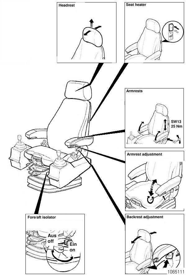
Operator's seat
The operator's seat (Fig. 2-36: and Fig. 2-37:) can be adjusted in several positions.
Never adjust the seat while driving. Concentrate on the road to avoid accidents.
Before carrying out any seat adjustments stop the machine and set the control levers to "0"
Fire extinguisher
The shovel is equipped with two four extinguishers. The conventional one is located near the operators cab (Fig. 2-38:), the carbon dioxide fire extinguishers are located near the electric motor and switching cabinets.
Handling
The shovel operator and the maintenance personnel must informthemselves about how to handle the fire-extinguisher in order to be able to act fast and efficiently in case of beginning fires. Such instruction should be given by a qualified instructor.
Extinguishing agent
The conventional fire-extinguisher is filled with 12 kg (26.4lb) Glutex. This extinguishing agent is used for fighting fires of classes A, B and C. Fires are extinguished fast, perfectly and without residues. The carbon dioxide fire extinguishers are intended for fighting fires of electrical parts.
Pull out securing pin (2, Fig. 2-39:). Strike knob (3) hard, then release again. Operate the extinguishing gun. After fire-fighting, the extinguisher must be refilled Immediately and prepared ready for use.
Inspection
Have the extinguisher inspected at regular intervals by an expert. This is required by local authorities and insurance companies and is in the interest of your own safety.
Have the fire-extinguisher checked at the prescribed intervals by authorized testing agencies.
Automatic fire-extinguishing system (optional)
The automatic fire-extinguishing system prevents fire from spreading.
It is, however, assumed that the machine is thoroughly cleaned of combustible and easily flammable substances.
The shovel operator and the maintenance personnel must familiarize themselves with the automatic fire-extinguishing system.
Such instruction should be given by a qualified instructor.
The fire-extinguishing system is activated automatically in an emergency.
Individual extinguishing circuits can be activated manually.
Inspection
Have the extinguishing system inspected regularly by an expert. This is required by authorities and insurance companies and is in the interest of your own safety.
Trainer's / instructor's seat
For operator training / instructing purposes it is often required that a trainer / instructor accompanies the operator in the cab.
For the safety of the trainer / instructor during shovel operation the cab is equipped with a second seat. This seat is installed behind the operator's seat (arrow, Fig. 2-40:).
Sit down on this seat and do not forget to fasten the seat-belt (if installed).
Do not leave this seat during the training / instruction session and /or as long as the machine is in operation.
Emergency escape device (optional)
See Description of the supplier.
Important hints
Before using operator shall have received adequate training.
The harness must be used by one person only. He is responsible for the appropriate use and maintenance.
Visual inspection is recommended prior to each use; if necessary it must be checked by an expert. Harness must be checked annualy (every 12 month) by an expert.
Taking on harness
Take harness out of handbag (15, Fig. 2-44:).
Pull loop (6) of the back support (1) between your legs to the front (Fig. 2-46:).
Pull loop (5, Fig. 2-47:) through loop (6).
Take on shoulder belts (2 and 3, Fig. 2-45:).
Pull loop (4, Fig. 2-47:) through loop (5). Press the hooking safety device (17, Fig. 2-47:) of the snap hook (16).
Pull back support (1, Fig. 2-45:) behind your body (Fig. 2-46:). The loops (4 and 5) are in front of your body.
Hang up loop (4, Fig. Fig. 2-49:) into snap hook (16).
If you have the harness put on in such a way in case of danger you can escape from the shovel (Fig. Fig. 2-51:).
Release hooking safety device (17, Fig. 2-50:).
MONITORING, WARNING AND CONTROL ELEMENTS
(Fig.
2-53)
No. Element Function Symbol
30 Lamp Illuminates the front side of the control column.
31 Pushswitch Emergency OFF
The entire electrical system is interrupted in all poles by the on-board circuit breaker. Even after actuation of the EMERGENCY STOP switch, medium voltage (6.3 KV / 6,6kV) is present (primarily) from the transformer station via drag cable and slip ring assembly to the circuit breaker.
32 Key-switch
33 Buzzer
Switches the low voltage system on and off.
Gives an acoustic warning signal if a fault is reported:
Electric motor
– winding temperature too high
– bearing temperature too high bord transformer temperature too high
Hydraulic oil level too low
Distributor gearbox temperature too high
Swing pump temperature (1 and / or 2; too high
Swing gearbox temperature (1 and / or 2) too high
Fault in lubricating system
Lower the equipment to the ground and switch off electric motor immediately if the buzzer (33) sounds and the BCS indicates a fault. The buzzer (33) continues to sound until the fault has been retified.
No. Element Function Symbol
33 Buzzer (continued)
Gives an acoustic warning signal if a fault is reported:
Distributor gearbox contaminated
Working pump (1, 2, 3, and / or 4; left and / or right) contaminated
Swing motor (1 and / or 2) contaminated
Swing circuit temperature (1 and / or 2) too high
Lubricating system pressure too low
Grease level in lubricating system too low
On-board voltage 24 V too low
The buzzer (33) continues to sound until the fault has been retified.
34 Buzzer
Gives an acoutic warning signal when the stick/boom angle to too small.
35 Terminals For electronic machine diagnostics.
36 Antenna (Optional)
37 Radio (Optional)
No. Element Function Symbol
41 Indicator lamp Medium voltage Lamp is lit up when the circuit breaker is switched on. Medium voltage 6.3 kV applied.
42 Indicator lamp Rotary field monitoring Lamp is lit up when the rotary field (phasing) is correct.
51 Button Electric motor ON Switches on the electric motor.
52 Button Electric motor OFF Switches off the electric motor.
CW:
The
Actuate
No. Element Function Symbol
81 Switch Not connected.
82 Switch Superstructure holding brake Blocks the superstructure.
Actuate switch only when the shovel is stationary. Do not use as service brake.
83 Switch Windscreen wiper Activates permanent / intermittent wiping.
84 Switch Screen washer Activates the wipe / wash function.
85 Switch Floodlamps Switches on the floodlamps on the operator´s cab.
86 Switch Floodlamps Switches on the floodlamps on the operator´s cab roof.
87 Switch Floodlamps Switches on the floodlamps on the hydraulic oil cooler.
88 Switch Floodlamps Switches on the floodlamps on the counterweight.
When switched it is possible to swing the uppercarriage and to drive the shovel even when the hydraulic ladder or the service station is in the lower position.
of damaging the ladder or the service station!
Be careful and swing the uppercarriage and drive the shovel very slowly and only a short way.
Actuate
Actuate
Lifts and lowers the bucket / backhoe bucket stick; Swings and brakes the superstructure. 116 lever Raises and lowers the boom; Tipping and rearward tilting of bucket resp. backhoe bucket. 117 Button Bottom-dump bucket
To the left - opens the bottom-dump bucket. To the right – closes the bottom-dump bucket. 118 Button
By-pass for the automatically switch off for stick- and /or backhoe cylinders (Option)
To the left – automatically stopped stickand/or backhoe cylinders can be driven slowly to the limit stopps. To the right – Not connected.