4 minute read
13.HYDRAULIC SYSTEM OF PLACING BOOM


Rotate the slewing bearing on the undercarriage and leave it hanging above the supporting surface, without resting it. As a guide, screw in at least three new screws (4) with relevant spacers (6). Carefully rest the slewing bearing and disconnect the hoist from the slewing bearing. Screw in all remaining new screws with the relevant spacers and cross-tighten them using a torque wrench. Tightening torque: WX145 = 270 Nm (199.14 lbf·ft) WX165 - WX185 = 280 Nm (206.51 lbf·ft) Mark the screws (4) already tightened. Apply the adhesive, as described, also to the supporting surface of the upper structure. Apply grease in a level coat to the teeth of the slewing bearing, so that the gaps between the teeth are completely filled. Rotate the upper structure on the undercarriage and leave it hanging above the slewing bearing without resting it. Carefully continue lowering the upper structure, inserting the pinion between the teeth. As a guide, screw in at least three new screws (3) with relevant spacers (5). Carefully release the upper structure. Screw in all remaining new screws (3) with the relevant spacers (5) and cross-tighten them using a torque wrench. Tightening torque: WX145 = 270 Nm (199.14 lbf·ft) WX165 - WX185 = 280 Nm (206.51 lbf·ft) Mark the screws (3) already tightened. Connect all hydraulic hoses and electric harnesses again to the rotary control valve and to the rotor. Remove the ropes from the upper structure. Fill and bleed air from the hydraulic system. Operate the machine and check all hydraulic hoses for tightness. The adhesive between the slewing bearing and the upper structure and between the slewing bearing and the undercarriage increases the load capacity of the screwed connection and contemporarily serves as a seal between the gaps. The adhesive hardens when exposed to air. A definitive rigidity is obtained after ca. six hours. Fully load the machine only after this time has elapsed.
3. ROTATION GEARMOTOR
The rotation device consists of an hydraulic motor (1) and a gearbox (2). The hydraulic motor consists of an axial-piston motor. The gearbox is used to rotate the upper structure by means of the coupling of the relevant pinion (3) with the internal teeth of the slewing bearing. The rotation device is installed on the main frame of the upper structure.
3.1 TECHNICAL SPECIFICATIONS
DIMENSIONS
DATA
WX145 WX165 WX185
Model S7/27/K45D Total ratio 23 27 Dry weight 114.5 kg (252 lb) 116.7 kg (257 lb) Engine A2FM45 Maximum differential pressure of the hydraulic motor 390 bar (5656.46 psi) Output torque 7 kNm (5163 lbs·ft) Minimum / maximum service pressure 14/80 Nm (10.32/59 lbf·ft) Nut torque 4050 Nm (2987.12 lbf·ft) Brake YES Maximum braking torque 475 Nm (350.34 lbf·ft) Number of inside discs 5 Number of outside discs 6 Thickness of inside discs 2.3 mm (0.09 in) Thickness of outside discs 1.1 mm (0.04 in) Maximum wear of complete discs pack 2.0 mm (0.07) Maximum piston stroke (wear) 3.1 mm (0.12) Rated stroke of new brake piston 1.1 mm (0.04 in) Oil capacity 3.5 litres (0.9 gal)
LUBRICATION
The gearmotor has two screw plugs (1) and (2) for oil filling and a plug (3) to be unscrewed for draining.
TIGHTENING TORQUES
3.2 DISASSEMBLY AND ASSEMBLY
DISASSEMBLY
Park the machine on a level and firm surface. Lower the attachment to the ground. Lower the blade and the stabilizers to the ground. Engage the parking brake. Lock the upper structure. Stop the engine. Move both hydraulic control levers in all directions, to release possible residual pressure inside the hydraulic system. Disconnect the pilot control. Place some wedges under the wheels so as to prevent the machine from moving. Mark and disconnect all hydraulic hoses. Disconnect the hose of the expansion tank (2) and remove the speed sensor (3) from the rotation gearbox (1). Close all openings on hoses and rotation gearbox with plugs in order to prevent dirt from entering. Using ropes, hook the slewing bearing (1) by means of eyebolts (5) and connect to a crane. Mark the position of the rotation gearbox. Unscrew and remove the screws (4). Using the crane, lift and remove the slewing bearing (1). The slewing bearing is glued to the supporting surface. To detach the glue, slightly hit the borders of the flange with a hammer.

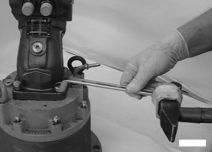
ASSEMBLY
Using a solvent, accurately clean the supporting surfaces of the rotation gearbox and of the upper structure’s frame from paint and grease. Then check for possible damage. The metal of the supporting surfaces must be bright, clean and degreased. Apply an adhesive strip with a thickness of approximately 1mm in the form of a ring around the hole of each fastening screw. The adhesive must be applied at a certain distance from the holes, in order to prevent that, when coupling the two surfaces, the adhesive enters the threaded holes. The adhesive must only be applied when the gearbox is ready to be installed. Using the ropes connected to the eyebolts (5), hook the gearbox to the crane, bring it to mounting position and rest it without moving it. Screw in the screws (4) and cross-tighten them, marking the screws already tightened. Tightening torque: WX145 = 270 Nm (199.14 lbf·ft) WX165 - WX185 = 250 Nm (184.39 lbf·ft) Connect all hydraulic hoses again. Assemble speed sensor (3). Connect the hose of the expansion tank (2) and fill oil into the gearbox. Bleed air from the hydraulic system.
3.3 DISASSEMBLY AND ASSEMBLY
MOTOR AND BRAKE
Disassembly
Unscrew and remove the screws (2).