3 minute read
12.HYDRAULIC SYSTEM OF DIPPER
2. SLEWING BEARING
The slewing bearing consists of an external ring integral to the upper structure, an internal ring integral to the undercarriage and a single (WX185) or double (WX145 - WX165) series of balls. The pinion of the rotation gearbox, controlled by the rotation motor by means of the gears of the gearbox itself, rotates around its own axis and makes a revolution around the centre of the internal ring of the slewing bearing, thus enabling the upper structure to rotate independently from the undercarriage.
TECHNICAL SPECIFICATIONS
WX145 - WX165
Teeth Module................................................................10 Number of teeth..................................................88 Pressure angle...................................................20°
WX185
Teeth Module.................................................................10 Number of teeth.................................................110 Pressure angle...................................................25°

DISASSEMBLY
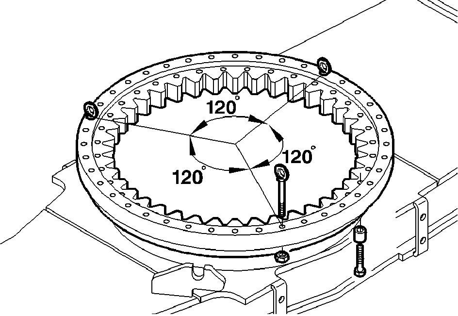
Park the machine on a level and firm surface. Lower the attachment to the ground. Lower the blade and the stabilizers to the ground. Engage the parking brake. Lock the upper structure. Stop the engine. Place some wedges under the wheels so as to prevent the machine from moving. Move both hydraulic control levers in all directions, to release possible residual pressure inside the hydraulic system. For slewing bearing disassembly, it is necessary to remove the upper structure. Disconnect all hydraulic hoses and electric harnesses from the rotary control valve and from the rotor. Close all openings on pipes and rotary control valve with plugs in order to prevent dirt from entering. By using chains or ropes (with a carrying capacity of 20000 kg (44000 lb)), sling the upper structure in its front and rear part. Hook these ropes to two cranes (with a lifting capacity of ~20000 kg (44000 lb) each) and slowly tension them without lifting the upper structure. Please remember that the internal ring (1) of the slewing bearing is fastened to the undercarriage and that the external ring (2) is fastened to the upper structure. Loosen and remove the screws (3) from the slewing bearing’s external ring (2). Keep the spacers (5) because they will be reused. Now the upper structure is detached from the undercarriage. Carefully lift the upper structure, until the pinion of the rotation gearbox is freed. Turn the upper structure away from the undercarriage. Using a hoist, hook the slewing bearing (7). For this operation, insert 3 threaded eyebolts (8), staggered by 120°, into the holes, fastening them with the nuts (9). Loosen and remove the screws (4) and keep the spacers (6) as they will be reused. Lift the slewing bearing (7) and remove it from the undercarriage.


ASSEMBLY
When the slewing bearing is new, eliminate the anticorrosive protection coat. Carefully clean all supporting surfaces of the undercarriage and the upper structure. The metal of the supporting surfaces must be bright, clean and degreased. Eliminate projections and burrs. Clean the holes of the undercarriage. Carefully clean the threaded holes of the upper structure and check the threads. If damaged, pass them again with the screw tap. Apply the adhesive to the supporting surface of the undercarriage. For this operation, use a painting roller, a hard brush or a plastic spatula. Do not let the adhesive enter the holes. Adhesive on threads causes higher friction and, therefore, an alteration of the tightening torque. Hook the new slewing bearing to the hoist. Rotate the internal and the external ring so that the mark (S) on the external ring is at 90° to the travel direction, and the mark (S) on the internal ring is on the opposite side.


