10 minute read
1 10] Flywheel damper ................................................................... 19.1

![1 10] Parking brake parking lock ...................................................... 33.1](https://static.isu.pub/fe/default-story-images/news.jpg)
General specification - Machine control panel
Dashboard and control panel
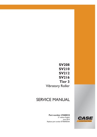
SS13G1 11 1 Dashboard and control panel identification
Item Designation Item Designation
1 Ignition switch 11 Engine Control Unit (ECU) diagnostics socket 8 Engine speed selector Switch panel 9 Power V iew display Indicator lamps
Hydraulic oil temperature gauge Fuses
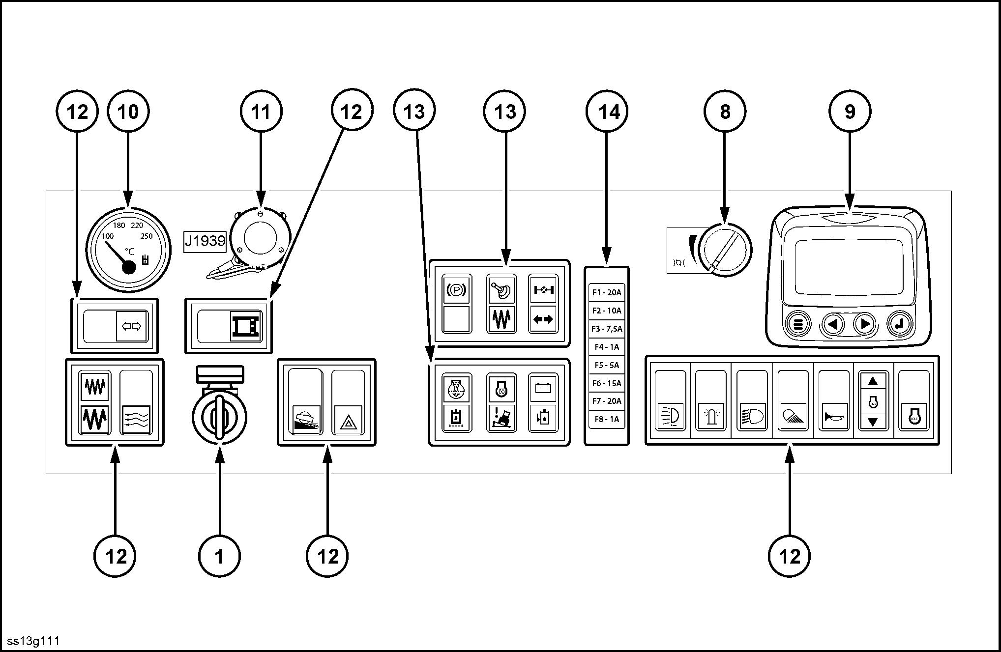
(1) Ignition switch
With the key in the ignition switch, the following occurs: • Position 0 - Electric power is available for the lights, cab / hood raising, and the cab climate control system. • Position I - The dashboard controls are operable. • Position - The engine will start.
NOTE: The ignition key is also used lock and unlock the cab doors, the service hatch underneath the cab, and the tool kit.
SS12J281 2
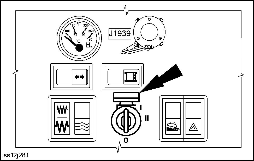
(8) Engine speed selector
T urn the selector dial adjust the engine speed from maximum minimum speed settings.
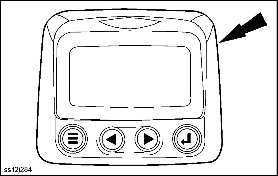
(9) Power V iew display
The Power V iew display is a multifunctional display that provides information the operator such the fuel level, engine hours, engine RPM, coolant temperature, and several other engine function parameters. The display can adjusted the operator ’s preference.
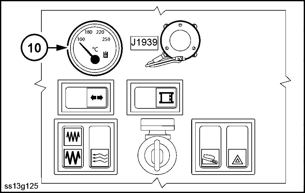
(10) Hydraulic oil temperature gauge
This indicates hydraulic oil temperature during operation. The optimal operating temperature is °C ( 122 140 °F ).
Oil viscosity class Highest permissible temperature
100 °C ( 194 °F ) °C ( 194 °F ) °C ( 176 °F ) °C ( 158 °F )
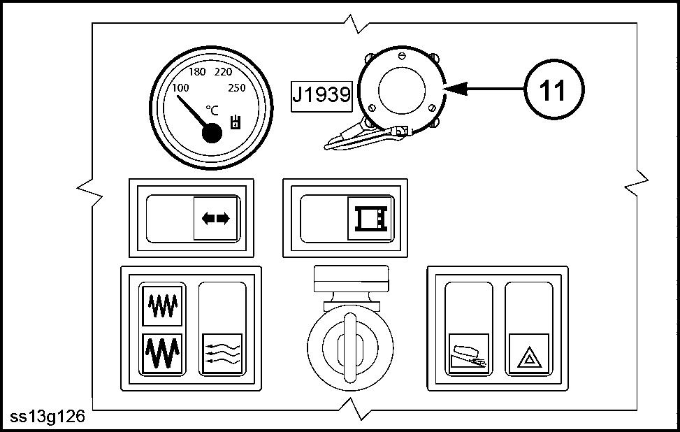
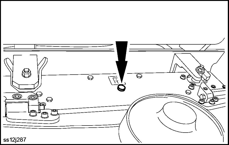
(1 Diagnostic port
Use the diagnostic port access the Engine Control Unit (ECU), engine actuator units, fault diagnostics, and parameter adjustments. NOTE: The ECU is designed process data about engine function and control engine operation.
SS12J283 3
SS12J284 4
SS13G125 5
SS13G126 6
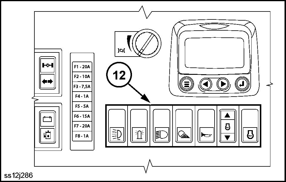
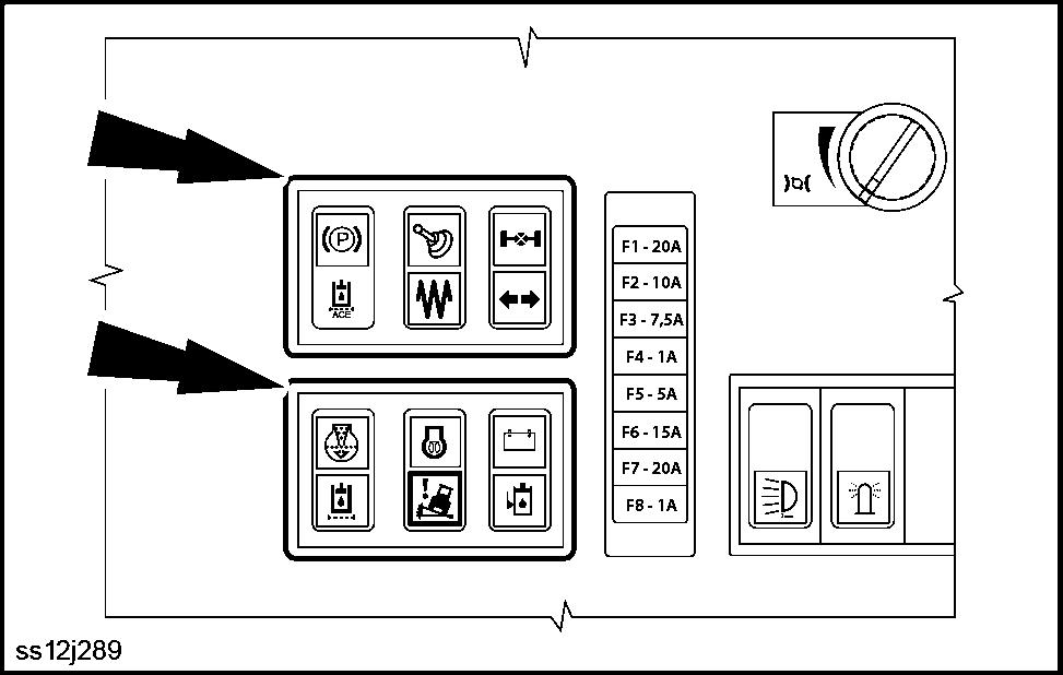
(12) Switch panel
Auxiliary lights (option)
Press the icon turn the auxiliary lights. Press the blank side the switch turn OFF the auxiliary lights.
SS12J286 7
Fender lights (front and rear) and headlights
This is a three position switch: • T position - Press the blank side the switch turn OFF the fender lights and headlights. • Middle position - Press the icon turn the fender lights and illuminate the dashboard control panel • Bottom position - Press the icon turn headlights.
Rear lights
Press the icon turn the rear work lights. Press the blank side the switch turn OFF the rear work lights.
Horn
Press and hold the icon sound the horn. Release the switch deactivate the horn.
Engine idle adjustment
Engine idle speed can adjusted from 800 - 1000 RPM . NOTE: The default setting is 850 RPM and the manufacturer recommends against adjustment for the reason that other machine parameters are set based off the default idle setting.
Engine idle switch
This switch must before starting the engine. NOTE: This protects the engine from starting high RPMs typically used during machine operation.
Beacon
To use the beacon: • Plug the beacon cable into the socket the rear the machine. • Press the icon turn the beacon. • Press the blank side the switch turn the beacon
OFF .
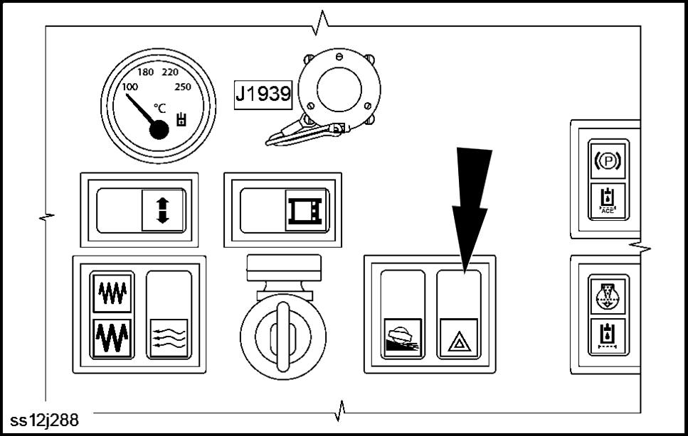
Hazard warning lights
Engage hazards warn others possible hazardous situations near the machine. • Press the icon turn the hazard lights. • Press the blank side turn OFF the hazard lights.
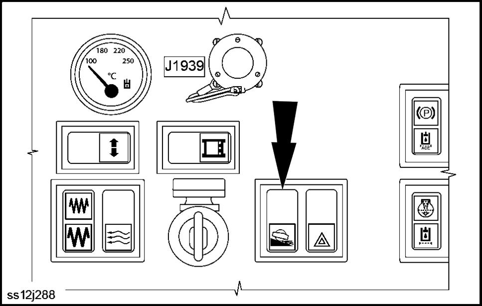
Drum slip limitation switch (option)
Use only move the machine onto the loading area a transport vehicle. • Press the icon turn the drum slip limitation. • Press the blank side the switch turn OFF the drum slip limitation.
NOTE: the machine is equipped with the drum slip limitation option, then the automated Anti - Slip Control (ASC) feature will not activate.
NOTE: When the drum slip limitation feature is ON, the vibration feature is blocked.
NOTE: The drum slip limitation will not activate if the
machine is in transport speed mode . T urn the transport speed switch OFF before using the drum slip limitation function.
SS12J287 8
SS12J288 9
SS12J288 10
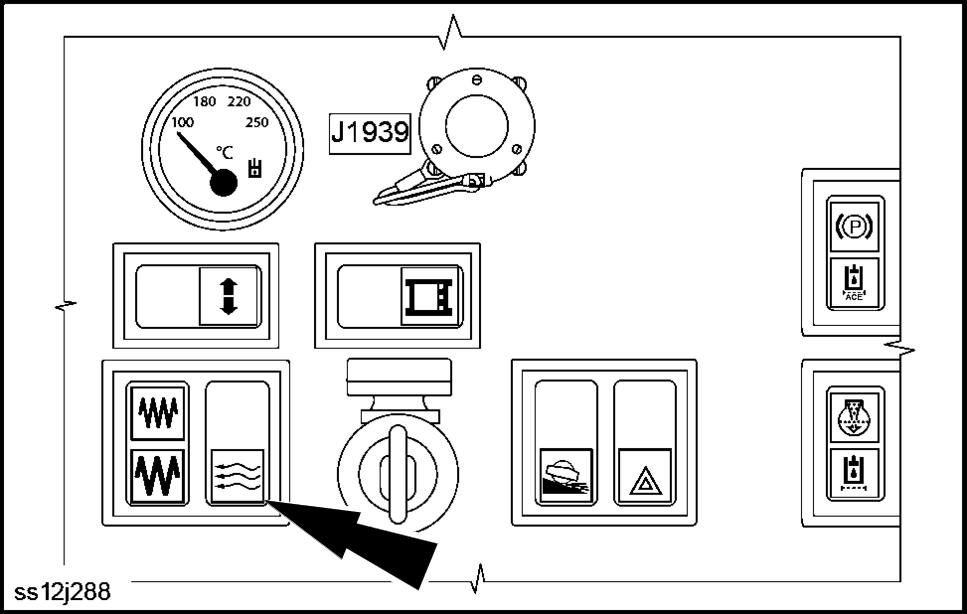
V ibration selector
The vibration selector switch has three positions: • T position - High frequency , low amplitude. Recom-
mended for granular materials. • Middle position - OFF , neither vibration option is selected. • Bottom position - Low frequency , high amplitude. Recommended for cohesive materials.
NOTE: Engage the vibration selection before the machine starts move and stop the machine before changing the vibration selection.
NOTICE: is not recommended engage change the vibration selection while the machine is moving.
Damage the machine hydraulic components may occur that will shorten the life the components.
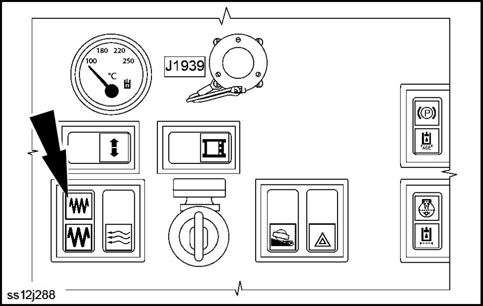
Fan switch (cab only)
The three position fan switch will enhance air flow inside the cab. • T position - f • Middle position - Fan is high • Bottom position - Fan is low
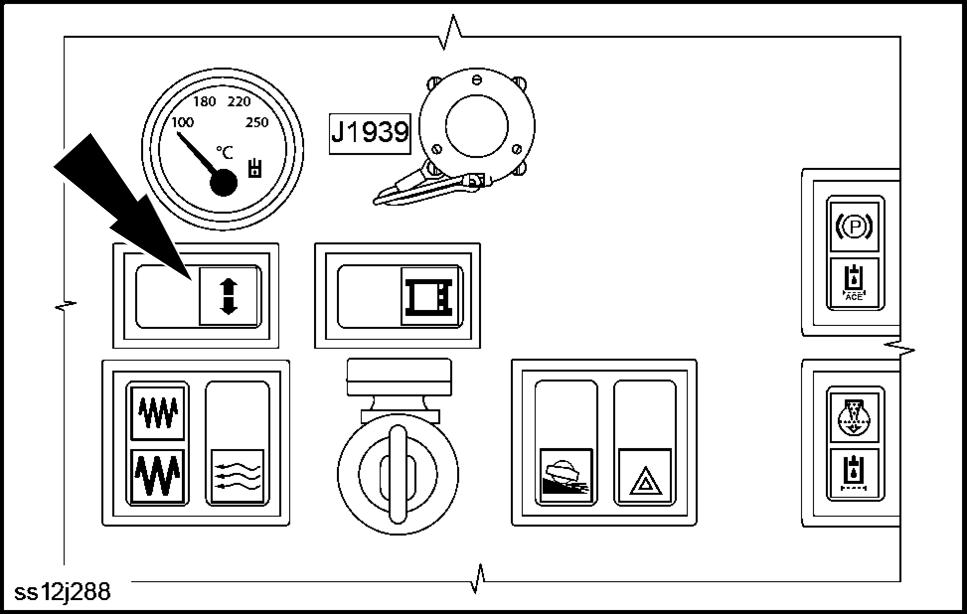
T urn signals - direction indicators
Use the turn signals inform other motorist which direction you intend turn the machine. • Press the right side the switch when turning the right. • Press the left side the switch when turning the left.
SS12J288 11
SS12J288 12
SS12J288 13
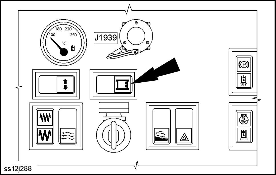
Compaction meter switch
NOTE: The Operator's Manual for the Compaction Meter is supplied separately .
(13) Indicator lamps
Parking brake
The indicator lamp is lit when the parking brake is engaged.
V ibration
The indicator lamp is lit when vibration is ON.
SS12J288 14

SS12J289 15
Direction indicators
The indicator lamp flashes and f when the turn signal is ON. NOTICE: Rapid flashing indicates a failure (defective bulb).
T ravel controller - neutral (idle) position
The indicator lamp is lit when the travel controller is in the neutral position. NOTICE: Make sure the travel controller is in neutral before starting the engine.
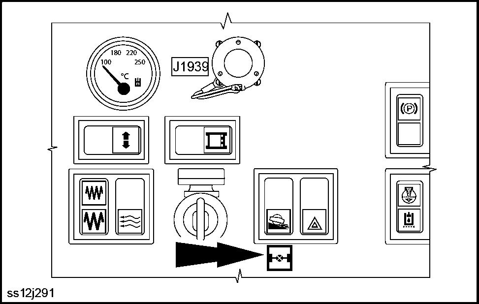
NOTE: The Anti - Slip Control feature is standard equipment the SV208 and SV210. is optional the SV212 and SV216 models.
Anti - Slip Control (ASC)
The Anti - Slip Control (ASC) indicator lamp is when the ACS system senses a lack traction. As a result the inter - axle dif ferential lock is engaged. When traction is regained the ACS disengages and lamp turns OFF . NOTE: The SV208 and SV210 operators not control the ASC feature, however the ACS feature will not engage when the drum slip limitation is active if the transport speed switch is active. NOTE: The SV212 and SV216 operators must press the ASC button (arrow) activate and deactivate this feature.
SS12J291 16
W ARNING
Roll - over hazard! Observe the maximum permissible gradient when driving uphill and across the slope. The values given may lower depending traction conditions and the actual machine weight. Failure comply could result death serious injury .
W1067A
ROPS - Roll Over Preventative System
SS12J289 17
A flickering ROPS indicator lamp with acoustic alarm indicates that the machine is a hazardous angle during cross travel a slope. V ibration mode will disengage and will not turn until the machine is a safe angle.
Engine preheating
When lit, the engine is preheating because low ambient temperatures. W ait until the engine preheat lamp is f before attempting start the engine.
Hydraulic oil filter clogged
When lit, the hydraulic oil filter clogged. NOTICE: Replace the hydraulic oil filter immediately .
Hydraulic oil level
SS12J289 18
When the hydraulic oil level indicator lamp is on, the hydraulic oil level in the tank is below the minimum required level. The machine will stop and the engine stalls. NOTICE: The engine can started once the defect has been repaired and oil in the hydraulic tank has been filled its recommended level.
Air filter clogged
When lit, the air filter is clogged. NOTICE: Replace the air filter immediately .
Battery lamp
When lit, the machine is using battery power . The light must turn OFF once the machine’ s engine is started. the light remains lit while the engine is running, the machine is experiencing a charging issue.
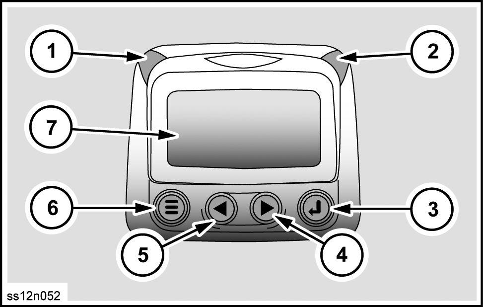
Multifunctional display
Item Designation
1 W ARNING - amber LED lights
Alarm for engine failure minimal fuel level in tank. 2 SHUTDOWN Alarm for major red LED engine lights malfunction.
3 ENTER Selects the Menu parameter , and conceals displays active error codes.
4 RIGHT arrow button - moves cursor right Illuminates data the display moves the parameter option the right down.
5 LEFT arrow button - moves cursor down left
Illuminates data the display moves the parameter option the left up. 6 MENU To enter selection exit button Menu. 7 Display
SS12N052 19
NOTICE: the red LED turns - reduce engine power , stop the machine immediately a safe place, and shut off the engine. not operate the machine unless the defect has been repaired! NOTICE: The amber LED light indicates engine failure. Reduce engine power , stop the machine immediately a safe place, and shut off the engine. not operate the machine unless the defect has been repaired!
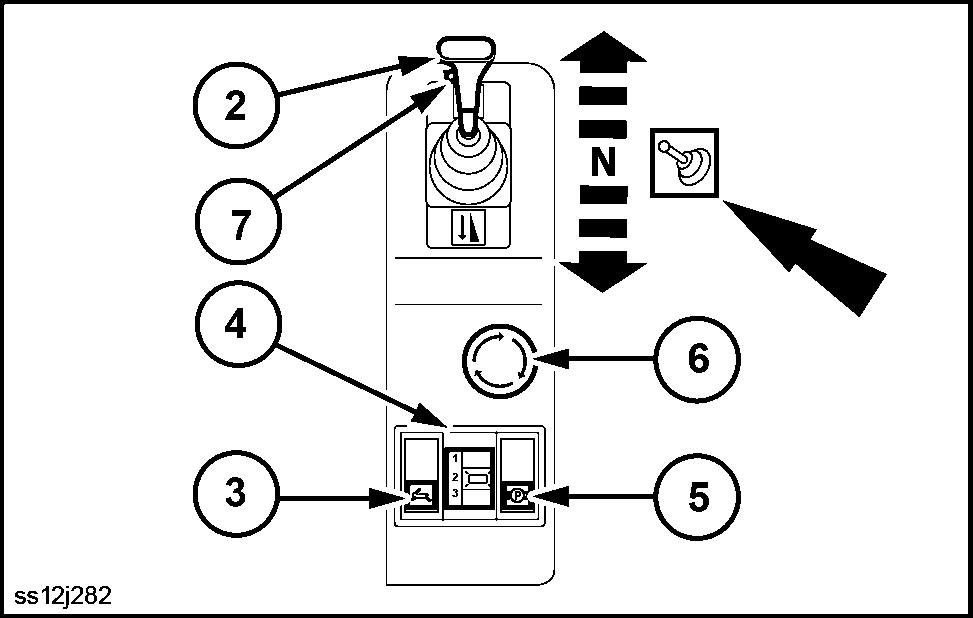
Right - hand side controls
(2) T ravel controller
This travel controller is used adjust driving direction and speed. Driving speed corresponds the degree which the travel controller is moved from the neutral (N) position. The travel controller locks into the position it is moved to. With the travel controller in the neutral (N) position the operator may turn the vibrations OFF with the button (7) located the travel controller . NOTICE: Move the travel controller the neutral (N) position before starting the engine.
SS12J282 20
(3) T ransport speed switch
With transport speed switch the machine will reach maximum speed reduced tractive force when the travel controller is moved completely forward backward. NOTE: The operator may press the transport speed switch while the machine is moving. NOTICE: not turn off the transport speed high speed. Sudden deceleration (retardation) will occur followed impact within the hydraulic system. T urn off the transport speed low speeds when the machine is stationary .
(4) Speed selector
Select from three operating speeds while driving. NOTE: The speed selection is ignored when the transport speed switch (3) is ON.
(5) Parking brake
Press engage disengage the parking brake. NOTE: the machine is stationary and the operator stands from the seat without first engaging the parking brake; the machine will brake automatically and the engine will shut OFF after 8 s.
(6) Emergency stop button
emergency situations press the emergency stop button. The machine immediately comes a standstill, the engine shuts down, and the parking brake engages. the emergency stop button is pressed. The button remains engaged and the machine will not start until it is disengaged. To disengage, turn the push button clockwise approximately 1/4 turn until it releases. NOTICE: Only press the emergency stop button in emergency situation.
(7) V ibration button
Press the vibration button the travel controller engage disengage vibrations. V ibrations can turned while driving.
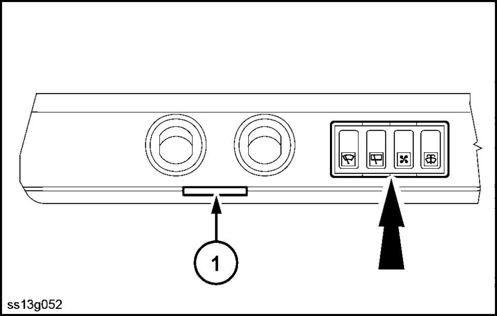
Overhead controls
Front Wiper switch
Rear Wiper switch
Fan switch – fan induces ambient air
Windshield W asher switch
Item Designation
1 Cab light
SS13G052 21