38 minute read
Modular distributor


sideshift lock control of the arm on the frame
Sideshift control (5a / 5b) in distributors is directly integrated in the distributor and is equipped with piloted one-way valve. With control in “sideshift locked” position, the one-way valve prevents the opening of the 4 hydraulic vices that lock the sliding of the mobile frame along the sliding guides, ensuring the continuous clamping. The clamping pressure of the 4 vices is maintained constant, through the intervention of the maximum pressure valve available on the distributor. By rotating the lever (5) to “sideshift unlocked” position and activating any distributor lever, the system pressure activates the one-way valve opening (through piloting), allowing unlocking hydraulic vices.
Replacement of bucket or tools
Position the equipment on the ground on a flat surface so that it does not overturn after the extraction of pins that fix it to the arm and proceed as follows: - Stop the machine, engage the parking brake. - Depressurize the auxiliary hydraulic system of the backhoe, operating the distributor lever that controls it. Depressurize and disconnect the machine auxiliary hydraulic system and remove the keys from the dashboard.
Danger During these operations it is compulsory to use safety clothing (goggles, helmet, protection gloves and safety footwear).
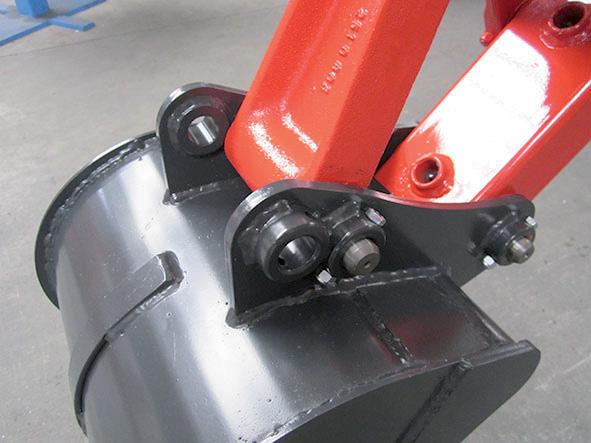
- If the equipment is connected to the backhoe auxiliary hydraulic circuit, disconnect hydraulic pipes of the equipment from fittings (4-5) placed on the swinging arm of the backhoe. Close with suitable plugs the equipment pipes and the fittings (6-7) on the arm. - Unscrew and remove screws (1) that lock pins (2-3). - Extract the two lateral pins (2-3) that fix the equipment to the arm. If pins resist, use a plastic hammer and a punch obtained from a brass or aluminium bar to avoid the deformation of pins and the accidental ejection of splinters.
Danger Do not allow any person to stand in the area of possible falling of the equipment.
- Climb into the driver’s seat of the machine and start its engine. - Carefully lift the arm till extracting it completely from the equipment. Pay the maximum attention not to drag or drop the equipment. - Move the backhoe arm and reach fixing points of the accessory you intend to use and, slowly moving the arm and the bucket cylinder match their connection points. - Engage the parking brake and stop the machine, or stay at the control position with the parking brake engaged and seek the assistance of another expert equipped with safety clothes (gloves, safety footwear, etc.). - Insert the pins (2-3) using a plastic hammer and lock them with their screws.
Danger Never align holes using your fingers: use a suitable centring device.
1
2
3
4-5 6-7
auxiliary hydraulic circuit connection (Deluxe line only)
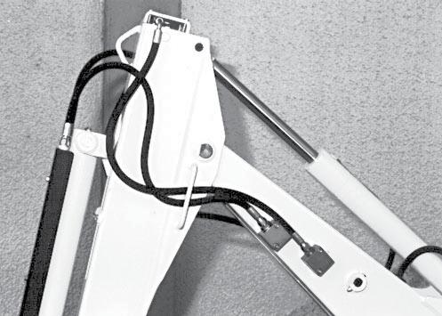
If the accessory applied must work with the hydraulic circuit, it is necessary to connect delivery and return pipes to the respective fittings of the backhoe auxiliary circuit (provided as optional), operating as follows: - Lay the tool on the floor, stop the machine and engage the parking brake. - Discharge the pressure of the auxiliary hydraulic system of the backhoe, operating on the lever that controls it. Depressurize and disconnect the working machine auxiliary hydraulic system and remove the keys from the dashboard. - Wear goggles and safety clothing (overalls, gloves, etc.). - Unscrew plugs from fittings (1-2) of the auxiliary circuit placed on two sides of the backhoe swinging arm and remove plugs placed at the end of the hydraulic pipes of the accessory. - Connect pipes of the accessory hydraulic system to fittings (1-2) respecting the circuit delivery and return. The Delivery must be connected to the fitting coming from block (3 or 4) indicated with “in” , while the Return must be connected to the pipe coming from the block indicated with “OUt”. - Climb into the driver’s seat of the machine and operate it in empty conditions for several minutes using all cylinders to bleed the hydraulic system from remaining air. - Using the “Auxiliary Control” lever of the distributor the accessory installed can be activated.
attention the use of the demolition hammer is extremely hard for the hydraulic system of the working machine. We recommend to carry out the installation of the demolition hammer at an authorised workshop and to intervene on the machine, which will be able to optimize the hydraulic system to make this use less hard.
attention When using the demolition hammer, the telescopic swinging arm must always be retracted and locked with the proper pin and the relevant safety pin.
1-2
3-4 5-6
7-8
Troubleshooting
Problem Main causes remedy
Controls do not respond Hydraulic system pipes not connected. Connect pipes. Power take-off not connected (Farming version). Connect power take-off. Auxiliary circuit not connected. Activate hydraulic circuit. Machine hydraulic system damaged. Refer to a workshop authorised to repair the machine. Hydraulic pump damaged. Replace pump. Low oil. Add oil up to the right level. Jerky movement of cylinders. Air in the hydraulic system. Make the machine operate empty for several minutes, using all cylinders (one at a time) to bleed the hydraulic circuit from remaining air.
Arm and/or stabilisers move without activating controls. oil overheat.
Worn cylinder gaskets. Replace gaskets.
Dirty filter. Replace filter.
Squeezed tubes. Check and change.
Low oil. Add oil.
oil leakage.
Slack fitting.
Tighten fitting. Worn gasket. Replace gasket. Poor bucket penetration. Machine hydraulic system damaged. Refer to a workshop authorised to repair the machine.
Worn hydraulic pump. Low fluid level. Replace pump. Restore fluid level.
Maximum pressure valve with out of calibration or worn. Check the calibration of the maximum pressure valve at an Authorised Workshop.
Dirty filter. Oil leakage.
Clean filter. Find leakage and remove it. Worn cylinder gasket. Replace gasket. Translation locked. Translation stop cylinders locked. Lift and open the arm with empty bucket and activate the relevant impulse cylinders to shake the mobile frame that should release the translation stop cylinders.
One-way valve of the hydraulic vice system out of order. Replace valve.
The mobile frame moves along longitudinal members of the frame.
Translation lock not activated. Place the diverter lever to "Translation locked" position. Oil leakage from relevant circuit. Check and remove the leakage. Worn cylinder gaskets. Replace gaskets.
General precautions
Before proceeding with use of the equipment you must have read and understood the previous chapters and in particular section “C - Safety”. If there are still some doubts, refer directly to the Manufacturer’s assistance service. Also read carefully the use and maintenance instructions of the operating machine on which the equipment is installed. The machine must only be used by qualified staff, which is aware of the position and function of all controls and the instructions given on the various plates. Uemme guarantees perfect mixing with a load equal to hole capacity (see “Technical specifications”)
Inspections and examinations before starting
For a correct use and compliance with the safety parameters, the following inspections must be carried out before every operation: - Correct hitching of equipment to operating machine.
Attention All blocking joint pins must have their cotters ensuring a correct coupling.
- Check integrity of the hydraulic hoses and any oil seepage from hoses and fittings. - Inspection of the carpentry and detection of possible fissures and cracks, paying special attention to the welded areas (discontinuities and cracks in paint that could anticipate damages to the structure). - Integrity and legibility of diagrams, symbols and warnings present on the equipment. - Safety devices correct operation.
Also check: - that the various parts intended to be greased have been lubricated. - that protections have been correctly fitted; - the conditions and tightening of the various parts; - that the envisioned daily maintenance operations have been carried out.
Attention When restarting work after a stop or after having moved away from the equipment temporarily, make sure that the devices which were set before going away have not been modified or that the equipment has not undergone vandalism or tampering.
Danger Before starting any operation, make sure that nobody is present within machine working area.
Pre-warn of the start of manoeuvres with relevant signals and make persons and animals present in the machine work area move away. Check the integrity of the control indications. Check the hydraulic oil level of the operating machine (see relevant Use and Maintenance Manual).
Attention If breakage, even partial, of equipment components is detected, immediately contact a workshop authorised by the Manufacturer, in order to perform the necessary repair operations before using the machine.
Attention It is strictly forbidden to perform makeshift repairs in order to start work.
During use
- It is strictly forbidden to lean on moving parts. - Do not use the equipment for any purpose other than that intended by the Manufacturer. - Always check in a precautionary manner that the operation of the equipment and of its units, even auxiliary, do not trigger dangerous situations for persons, objects or animals. - Get individual protecting systems foreseen by the prevailing accident prevention standards. - In case of risk forecast, stop the operations and start working again only after all risk conditions have been eliminated. - Before beginning work, inspect the operating area to pre-emptively ascertain the presence of obstacles.
Avoid hitting against obstacles since they could damage the equipment or jeopardise the stability of the operating machine.
Attention Pre-emptively check for the presence of pipes or manhole covers, as well as ground loading capacity.
- Put the equipment in transport position, even for brief journeys (see “Road circulation”). - In case of operation on inclined ground always turn the bucket upstream; otherwise the stability of the machine is prejudiced. - Always climb up or downhill with the bucket lowered and facing the hill. - Never exceed the maximum gradients allowed by the Manufacturer of the operating machine.
Danger During the job, always keep the machine manoeuvre area under control and prevent persons and animals from approaching. stop the operating machine immediately if safety standards are not respected.
- Make sure you have full vision of the operating area.
Make sure that lighting is sufficient in the event of night-time work.
If necessary, indicate the work area using the relevant signs. - Do not work close to open excavations, without respecting the minimum safety distances. - Activate controls only from the control position of the machine, or from the backhoe’s seat when available and the work allows it. If there is a minimum risk of overturning, of rockfall or fall of material, it is strictly forbidden to use the control station on the external seat. - Before moving backhoe arms, engage parking brake of the machine, remove safety locks of the arms and lower stabilizing feet. - Get stabiliser plates down, lying on the ground, without discharging the tyres of the machine, to avoid the excessive raising of it. This is extremely important to avoid losing the tyre grip which improves the stability, i.e. relying only on stabilisers to carry the load and the machine.
- Do not activate the backhoe before having checked that stabilisers are positioned on a solid and compact ground. Check the degree of stability according to the operating conditions.
If the ground on which stabilisers lean is not compact or is soft, it is necessary to increase the support surface of stabiliser plates, interposing proper plates to increase the support, or hardwood planks. - Before handling the backhoe, make sure that connection pins of the arm and of the equipment and pins that fix the backhoe to the machine are correctly inserted and kept by proper cotters or safety locks. Moreover make sure that the wedges or pins of the quick coupling devices between backhoe and machine are perfectly inserted inside their seats. - Avoid sudden movements, act smoothly and gradually on control levers. - Rotate with suspended loads, not dragging on the ground. - Do not work close to power and telephone lines, without respecting the minimum safety distances. - Inform about the operation start with specific signals. - Avoid to rotate the arm over working or transit zones. If that cannot be avoided, inform about the operation start with specific signals. - Excessive heating of the oil provokes damage to hydraulic circuit gaskets and the deterioration of the fluid. Heating may be caused by an extended working with jack at end of stroke or by an excessive pump flow rate. In the first case, just avoid to operate controls always at end of stroke, while in the latter case it is necessary to decrease the engine rpm of the machine. - Before starting operations, make sure you have full vision of the operating area. Make sure that lighting is sufficient in the event of night-time work. Always signal the working area with proper signs. - Do not perform adjustments or interventions on the equipment while it is working.
Danger Do not dig too close or under the stabilisers. Do not dig near underground power lines. Be careful when lifting the stabilizing feet, because in some cases they represent the only reliable support against the machine overturning during digging operations.
Attention Check preventively for the presence of pipes or manhole covers, as well as ground solidity. Always put the control lever of the direction inverter or gearbox in “NeUTRAL” position when working with the backhoe. While working always keep the working area under control and prevent people from approaching. If safety provisions are not respected stop work immediately. At the end of the work, before leaving the machine, place the machine and backhoe in a flat place, with limited access to unauthorised people, and lean firmly on the ground the stabilisers and the bucket. stop the machine and engage the parking brake. Never leave the ignition key on the machine.
Climbing onto and off of the operating machine
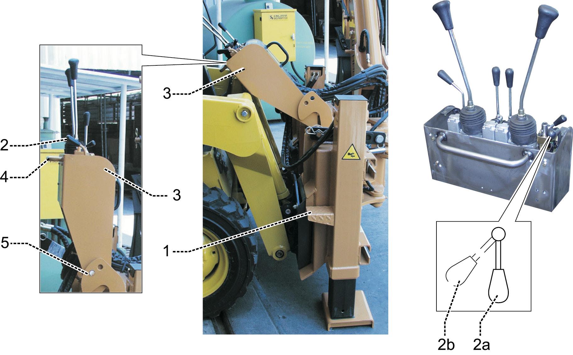
On the right side of the backhoe (and in some models also on the left side, when there is enough space) there are footboards (1) to facilitate access to the driving position of the machine. Always go up and down from the right side of the machine, paying maximum attention not to stumble in the hydraulic pipes that supply the circuit of the backhoe. - Turn the lever (2) clockwise (2b), until the control unit (3) is unlocked. Grasp the handle (4) and lift in vertical position the distributor support (control inside the cab), to provoke the intervention of the snap locking device (5) that locks it in vertical position and the lever (2) gets back to position (2a). - Enter in the cab of the machine and, before sitting in the driver seat, grasp the handle (4), rotate the lever (2) clockwise (2b), that unlocks the snap locking device, and lower the control unit (3) supporting it, to avoid accidental shocks to the lower limbs. - To get off the machine turn the lever (2) clockwise (2b), until the control unit (3) is unlocked. Grasp the handle (4) and lift in vertical position the control unit, to provoke the intervention of the snap locking device (5) that locks it in vertical position and the lever (2) gets back to position (2a).
Danger Do not climb onto or off of the machine using systems other than those prescribed by the Manufacturer (such as the wheels of the machine or other supports as a step). Always use the slip-proof steps or platforms provided by the Manufacturer of the machine and equipment.
Road circulation
When riding on the road, strictly comply with regulations in force regarding road transportation in the country where you are operating. - Make sure that oil does not leak on the road. - Turn the equipment in such a way for the driver of the operating machine to see well. - Do not circulate on roads if the application is not type-approved in the ways envisioned and recorded in the operating machine log book. - If the machine-equipment coupling is type-approved to circulate on roads, respect the following provisions unless they do not oppose those indicated on the type-approval certificate (or similar document): • Yellow rotary light present on the operating machine. • Move at a moderate speed, paying attention to pedestrians, bicycles and obstacles. • Block any pins present with the relevant safety cotters. • Position the signal devices (profiles or reflecting panels for projecting loads, retro reflectors, lights, etc.), which are requested by the standards in force or indicated on the type-approval certificate. - Circulating on roads or on public land, as long as it is allowed, the regulations prescribed by the Highway Code in force in the country of use must be respected. - During road circulation, pay great attention close to inhabited areas, crossroads, bridges, subways, level crossings etc.
Attention If the equipment is not type-approved for road circulation, it must be disconnected from the machine and loaded onto a suitable means of transport.
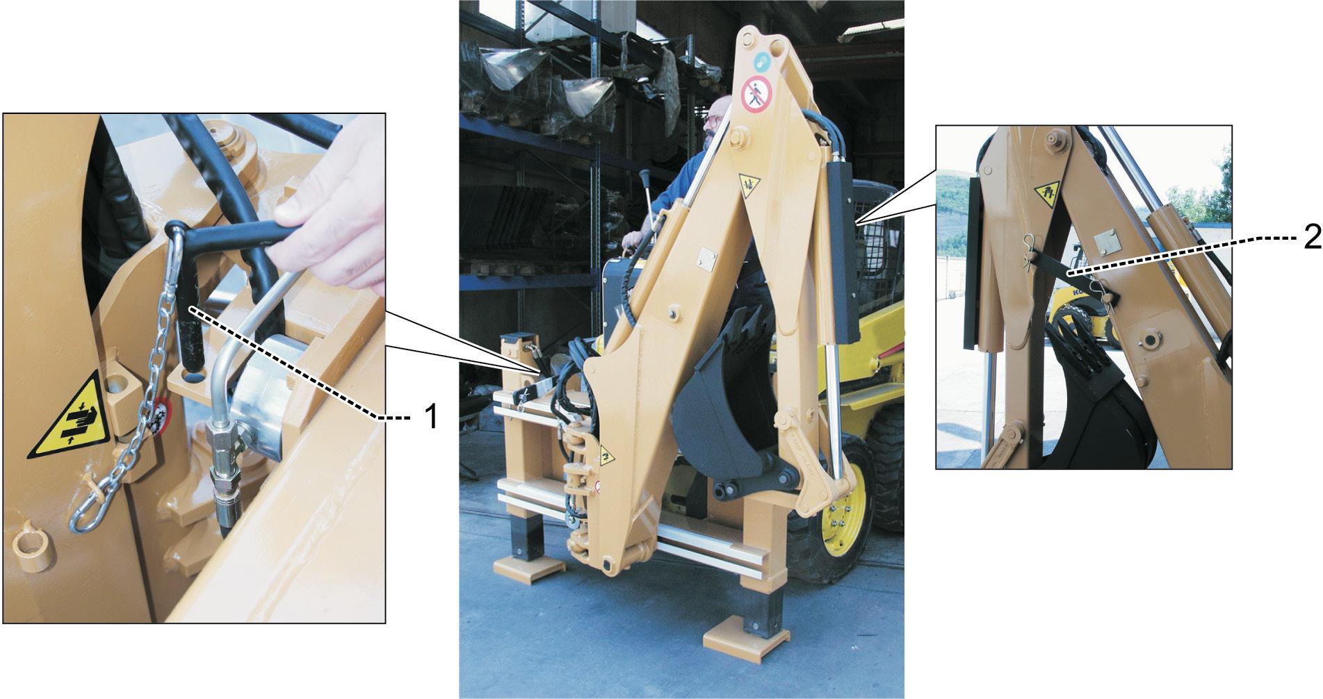
Close and lock the backhoe proceeding as follows: - translate the backhoe art to end of stroke on the right side of the frame and lock the translation; - Completely close the bucket and the swinging arm; - lock the swinging arm with the main arm installing the red connecting rod (2) on the proper pins; - Completely lift the main arm, rotate it completely to the left and lock it into position by inserting the red pin (1); - lift the stabilizing feet to the highest position; - fix the connecting rod (2) and the pin (1) with proper safety cotters.
Recommendations for using the equipment in cold climates
If the equipment must be used in cold climates, with the temperature between -10°C and +5°C, it is very important: - Check that the hydraulic oil contained in the machine is suitable for these temperatures (see lubricant table, if provided with the working machine). - Before starting the equipment, start the working machine and operate one at a time all the controls for several minutes always at empty conditions to bring the hydraulic system to the correct temperature.
Operating speed
Operating speed of the backhoe depends on the number of engine rpm. Oil flow must not exceed the value indicated in chapter “D - Technical Specifications”, according to the backhoe model. Conform the engine speed (on average about 1800 rpm) in order not to exceed this flow. Excessive speed with consequent increase of the pump flow, causes the overheating of the hydraulic fluid, forced to flow through the outlet of the distributor maximum pressure valve.
stabilisation of the backhoe
Stabilising feet installed on the backhoe are independent and equipped with large road pads, to ensure maximum stability. After having reached the working area, position the backhoe in order to make the work easier, without compromising safety. Respect minimum distances required (from digs, ditches, power lines, etc.), choose the point where stabilisers must be placed, so that the ground is levelled and solid, then proceed as follows: - lower stabilisers feet one at a time alternatively, operating the relevant distributor levers; - level the backhoe, without taking the wheels of the tractor or of the machine off the ground, since they contribute to stability; - in case of works on slopes, level the machine always keeping one of the two rear wheels in contact with the ground.
Danger If the ground is not solid enough, increase the support surface of stabilisers, interposing between stabilizing feet and the ground, proper plates of stable material (hardwood planks, etc.), ensuring that the foot leans in the centre of the plate. Always respect general safety rules in force in each country, before stabilizing and using the backhoe.
Dig
In special cases (limited manoeuvre spaces, particular conformation of the ground, etc.) it may be necessary to change the mode of use of the backhoe described in this chapter. In these cases the experience of the operator and the compliance with safety rules will be decisive to choose the most appropriate manoeuvres. - stabilize the machine as indicated in the previous chapter; - operating the relevant control, open the bucket so that teeth are aligned with the swinging arm; - open arms and lean on the ground the bucket teeth in the point to dig. The best results are obtained with the main arm and the swinging arm forming an angle of about 120°; - operating on the arm controls make the bucket penetrate the ground. A better penetration force can be obtained by combining the movement of the swinging arm with the movement of the main arm; - with the bucket into the ground simultaneously close the swinging arm and the bucket, until the bucket is full. If the bucket stops, slightly lift the first arm and keep on filling the bucket; - lift the bucket over the top of the dig, adapting its position, in order not to drop the material collected, then rotate the arm and empty the bucket on the pile of removed material or on the mean of transport of the material, dropping the material at the minimum distance; - repeat the previous operations, until the work is completed.
Danger During digging there is always a risk of landslides or landslips. Always check the conditions of the ground and of the material piled up. Prop up where necessary to prevent landslides or landslips, paying the maximum attention in critical cases (dig near previous excavations filled with filling material; digging of degraded material or poorly compact; digging in areas prone to vibrations, caused by other working machines, train paths, busy roads; digging in wet areas or with seepage of water, etc.).
Arm translation
The lateral motion of the arm with respect to the backhoe frame must be carried out with stabilized machine, proceeding as follows: - rotate the translation control to “Translation unlocked” position to activate the release of vices that lock the arm base on the frame sliding guides; - open and shake the arm until the hydraulic vices release; - rotate 90° the arm in the desired translation direction; . lay firmly the bucket to the ground, fixing teeth in the ground; - moving the main arm and the swinging arm, drag the arm base to the desired position; - rotate the translation control to “Locked translation” position, making the arm base moving together with the backhoe. - operate the bucket or main arm control until you reach the end of stroke of the cylinder involved. In this way you activate the maximum pressure valve that ensures the locking of hydraulic vices with the maximum pressure of the system.
Attention It is strictly forbidden to operate with the translation unlocked.
Foreword – General warnings
Attention All the operations described in this section are the responsibility of maintenance operators, qualified and trained personnel for this purpose.
Danger Even if not expressly instructed, it is imperative that the machine is cut off from all power supplies before any maintenance work (part replacement, repairs, cleaning, lubrication, etc.) is performed.
Make sure that no other persons are present close to the equipment during use and maintenance.
Attention Wear suitable Personal Protective Equipment before carrying out maintenance operations.
Maintenance operations must be carried out at least at the recommended intervals, although the exact frequency depends on the conditions of use of the machine. During maintenance, repair, cleaning and adjustment operations, indicate machine standstill in a visible manner using a sign positioned in the driver’s seat or on the distributor indicating “WORK IN PROGRESS”.
LAVORI IN CORSO NON EFFETTUARE MANOVRE
Attention Before starting the machine up again, correctly refit and tighten all the parts which have been removed (in particular fixed and moving covers and safety components).
Any operation NOT listed below must be performed by specialised personnel authorised by the Manufacturer.
Danger Read the “Safety” section of this manual in its entirety before starting work.
- Methodical and accurate maintenance reduces the risk of damage or accidents and preserves the equipment over time. - The main cause of accidents is due to: • lack of oil and grease; • dirt accumulated on the various units or components; • safety devices out of order; hydraulic system failure (worn flexible hoses, loose fittings; etc.); • errors made during maintenance.
- If some operations require the operating machine arms to be lifted, these must be suitably locked in position with relevant stays. - Never postpone maintenance or repair operations. - Always follow maintenance and repair procedures requesting previous authorisation. - Stop the engine and make sure that the pressure has been discharged from all systems before removing casing, guards and covers.
See the machine Use and Maintenance Manual. - Use the relevant handholds and steps to climb on and off of the machine. - Do not wear rings, watches, jewellery, open and loose clothing, e.g. ties, ripped items, scarves, unbuttoned jackets or overalls with open zips that may become entangled in moving parts.
It is advised to use approved items for accident-prevention purposes: helmets, slip-proof shoes, protective gloves, anti-drumming hearing protection, reflecting jackets, anti-dust masks, breathing apparatus, safety goggles, when the job requires the same.
Consult the employer for the safety prescriptions in force and use of the accident-prevention devices. - Do not go under the equipment when this is just lifted. - If it is absolutely necessary to lift the equipment disconnected from the working machine, use suitable means (see “Lifting and handling”). After having lifted it, always insert a stand or tail prop, leaving the lifting means always in traction. - Never introduce your head, body, limbs, hands, feet or fingers into a shearing area, without guards, without first having locked tightly any parts that can move. - Never align holes or slots using your fingers; use a suitable centring device. - When using compressed air to clean parts, use protective goggles with side visors. Limit pressure to a maximum of 2 bar. - Never use petrol or solvents or other flammable liquids for cleaning. Use authorised, non-flammable and non-toxic solvents available on the market. - Do not lubricate, repair or adjust the equipment when it is working, unless expressly requested in the Use and Maintenance Manual. - Never use tools improperly or in bad conditions, e.g. pliers instead of the special spanners etc. - Keep the maintenance area clean and dry, and immediately dry any traces of water and oil. - The leaks of pressurised fluid through small holes are almost invisible and can be strong enough to hole your skin.
Before checking for leaks, protect your eyes with protective goggles with side visors.
Do not use your hands, but use a piece of cardboard or wood, to detect suspected leaks of pressurised liquid. Wounds caused with pressurised fluid can cause serious infections. In this case, consult a doctor immediately. - Do not gather oily or greasy cloths as they constitute a fire risk.
These cloths must be deposited in a closed metal container. - Immediately replace any Danger, Attention or Instruction warning plate that is no longer readable or missing.
Attention Never perform jobs with the removal or deposit of material (welding, drilling, sanding) without the Manufacturer’s authorisation and instructions.
- At the end of maintenance or repair operations, before starting the machine, check that no tools or other material are left inside the compartments containing moving parts or close to moving parts. - Always ensure that both the machine and relevant accessories are in good order.
Danger - Before restarting the machine ensure that all maintenance operations have been completed correctly and that starting of the machine will not result in any risk conditions. - immediately after having completed the operation, restore and check the safety devices that were removed during the maintenance or repair operation.
Attention All untreated surfaces (guides, racks, etc.) should be cleaned and then lubricated.
Key to symbols used in the chapter:
Brush greasing
Inject grease through the grease nipple Grease by means of a grease gun
consultation of technical documents
Before performing maintenance work on the machine, read the technical documentation supplied by the Manufacturer and the suppliers of individual commercial parts of the machine. In particular consult: - the “operating instructions”; - the “user instructions for the operating machine”; - the diagrams of the electrical, hydraulic, pneumatic systems, etc. In any case work on the machine only if you are in possession of adequate technical know-how. The Manufacturer’s technical service is at your complete disposal for any information concerning maintenance work to be carried out on the parts supplied.
Attention in case of operating faults, do not attempt to solve any anomalous situations that may occur using makeshift means.
Spare parts
The use of non-authentic spare parts may cause machine malfunctions, which in turn may lead to hazardous situations for the operator and any individuals working near the machine.
Attention Always use authentic spare parts.
Layout of equipment
- Before carrying out any maintenance operations, place the backhoe as follows: - stabilising feet placed on the ground; - bucket completely open placed on the ground; - tractor gear lever or direction inverter on neutral position; - parking brake engaged and wedges under the wheels; - engine stationary; - ignition key removed from the dashboard. If the equipment must be disconnected from the operating machine, see “Equipment removal”.
Pollution hazard it is prohibited to disperse old brushes, rubber or plastic components, solvents, oil and lubricants into the environment. collect and dispose of these components according to the provisions in force in each country.
Scheduled maintenance
Daily checks
- Check the oil level in the tank or in the machine tank as indicated in the respective user manual. - Check the flexible hoses, the fittings and the other components of the hydraulic system so as to prevent breakage and pressurised oil leaks. Eliminate any leaks in the hydraulic system. - Check that all the guards are correctly installed and that the safety devices are efficiently operating. - Check that the structure of the equipment and of the respective accessories is in good conditions and shows no signs of cracks or deformations. - Check that the backhoe can be easily activated and that controls go back easily to neutral position. - Wipe all unpainted parts with a cloth soaked in oil. - Wash the equipment. - Refill with grease all the greasers available on the backhoe.
Every 200 operating hours or every month
- Check the integrity of seals available on the backhoe. If necessary refer to our Service Department to restore missing or damaged seals. - Check tightening of bolts that connect the different parts of the backhoe. - Check tightening of hose and pipe fittings. - Check securing devices and other safety devices. - Check that safety stickers and instruction plates are available and legible. If not, replace them or attach the missing ones. - Clean filters of the hydraulic system. - Check oil level. - Check multiplier oil level (if available). - Check integrity of hydraulic pipes protective sheaths. In case of excessive breakage or tear, replace them with Original Spare Parts.
- Perform an operation test of the backhoe, listening that there are no abnormal noises.
Otherwise, determine the cause and eliminate the problem.
Every 200 operating hours or every year
- Clean the backhoe. - Contact a Workshop Authorised by the Manufacturer to have an operation and safety check performed. - Check the equipment used. - Replace completely the hydraulic fluid in the backhoes equipped with control unit. - Replace the drain filter of hydraulic fluid (if available).
Check of hydraulic fluid level
- Place the machine on a flat surface, extend to the maximum all cylinders available on the backhoe, stop the machine and engage the parking brake. Check the hydraulic fluid level, as indicated in the “Use and Maintenance Manual” of the working machine and in case fill in with oil of the same type.
Attention Do not mix oils of different brand or type, use the same type of oil contained in the tank.
Lubrication
Preliminary information
Pollution hazard It is prohibited to disperse waste oil into the environment. Place oily cloths, lubricants, solvents and filtering cartridges inside suitable containers and dispose of them in compliance with the provisions and Standards in force in each single country.
Attention Do not mix different types of oil, restore the level of lubricants exclusively with lubricants of the same type as those contained in the respective tanks. Only use the lubricants recommended by the Manufacturer or the corresponding lubricants indicated in the relative table.
Danger Only use the greases indicated. Other products may be incompatible with the product used by the manufacturer for the first greasing. incompatible greases that are mixed or used at a second stage can develop substances affecting machine operation with potentially serious safety consequences.
Lubricating grease comparative table
Grease tOtAL MOBiL ESSO AGiP iP BP
HERELDA 2 FARM T.GREASE CAZAR K2 GREASE 16 AUTO GR CH GREASE A
Grease
MULTIS EP 2 MOBILUX EP 2 Protective oil OSYRIS ACR MOBILARMA 246 BEACON EP 2
GR MU EP 2 ARTHESIA GR EP 2 RUSBAN 398 RUSTIA 82 IDEX FLUID PM GR 2 ENERGREASE NM EP 2 C.P.F. 21
Lubricating points
Lubrication intervals scheduled by the Manufacturer are:
- Grease every 8 working hours or every day using a pump for greasers.
- Brush grease at least once a day.
- Check the level once a month and change the oil about every 1200 working hours.
- Check daily and if necessary restore the level of hydraulic fluid in the machine with fluid of the same type of the one contained in the tank. When scheduled, change the hydraulic fluid.
Attention in heavy duty work and environmental conditions, shorten the frequency of the lubrication intervals.
Supply grease nipples
Top-up the greasers present on the equipment as follows: - Always clean the greasing heads to prevent the infiltration of dirt. - Feed all greasers using a standard grease pump. Fill the type of grease described in the “Lubricants correspondence table”. Clean the excess waste grease using a cloth.
Attention in heavy duty work and environmental conditions, shorten the frequency of the lubrication intervals.
tightening torque table
Unless differently indicated, tighten the screws present on the backhoe using the tightening torque values (Nm) indicated in the following table.
Dimensions of the screws 8.8 Tightening torques (Nm) class 10.9
12.9
M4 2.7 3.8 4.6 M5 5.5 8.0 9.5 M6 9.5 13.0 16.0 M8 23.0 32.0 39.0 M10 46.0 64.0 77.0 M12 80.0 110.0 135.0 M14 125.0 180.0 215.0 M 16 195.0 275.0 330.0 M18 270.0 390.0 455.0 M20 385.0 540.0 650.0 M22 510.0 720.0 870.0 M24 660.0 930.0 1100.0 M27 980.0 1400.0 1650.0 M30 1350.0 1850.0 2250.0
Ordering spare parts
Consult the specific spare parts catalogue when you need to order spare parts. Spare parts must be ordered from the retailer or assistance centre and the orders must include the following indications: - Type and model of equipment. - Part number of the requested part.
If you do not have this number, list the number of the table in which the corresponding reference is provided. - Name of the part and desired quantity. - Preferred transportation means. If this item is not specified, the retailer or assistance centre, though dedicating special care to this service, will not respond to shipping delays due to force majeure.
Shipping costs are always charged to the addressee.
Placing the machine out of service for a prolonged period of disuse
In the event of prolonged disuse perform the following operations on the machine: - Thorough cleaning. - Get the equipment in transport configuration. - Lubrication of all moving parts. - Anti-rust surface treatment on all unpainted metal parts (apply oil or MoS2 spray). - Cover the machine with a waterproof tarpaulin to protect it from dust and damp. - Store in a dry and protected place with access limited to authorised persons only.
Service life
The actual service life of the equipment, if all the checks, the envisioned maintenance operations and inspections are carried out, is 10 years from its first start up. After this period of time the use of the equipment is prohibited if not overhauled and checked by the Manufacturer. Further overhauls must be carried out every 2 years.
control register
Storage instructions
This Control register must be considered as a part of the equipment and must accompany it during its whole life until its final dismantling.
instructions for the drawing up
These instructions are supplied according to the provisions known when the equipment was first placed on the market. The register is arranged to take note of the following events regarding the useful life of the equipment according to the layouts proposed: • Transfers of ownership • Replacing mechanisms, structural elements, safety devices and relative components. • Serious failures and their repairs. • Maintenance and periodical checks.
note Whether the sheets of the present register were not enough, add the necessary sheets, drawn according to the schedules here indicated. The user must include the identification data of the equipment on the additional sheets. These sheets will be an integral part of the present register.
Authorised persons
This documentation must be drawn up by the owner of the equipment, or by someone directly delegated by him, as must the tests to be carried out by specialised personnel; verification calculations (stability, secondary frame, etc.) must be carried out by legally qualified persons.
Storage of the control register
This Register, summarising the essential technical features and data of the equipment, must be kept for the entire working life of the equipment. The subsequent checks to be carried out within the legally envisioned times and methods and the execution of the servicing checks must also be recorded on it, as well as the inspections before commissioning. The inspections and any extraordinary checks to be carried out in case of constructive changes, structural repairs or use change compared to that established by the manufacturer must also be recorded.
Identification of equipment
Equipment model: ................................................................................................................... Serial number and year of manufacture: ................................................................................ Type and frame n° of operating machine: ..............................................................................
Manufacturer information: U.EMME s.r.l.
Via dell’artigianato 19 - 47015 Modigliana (FC) Tel. +39 0546 941725 - Fax +39 0546 940050 e-mail: info@uemme.com www.uemme.com
note For all technical data of the equipment and operating instructions, refer to the “Use and maintenance manual” this register is attached to.
Operating machine
- Manufacturer: ......................................................................................................................
- Frame Number: . .................................................................................................................
- Plate: ...................................................................................................................................
equipment:
- Manufacturer: ......................................................................................................................
- Type: ............................................ Year of manufacture: ..................................................
- Date of commissioning: ......................................................................................................
- Serial No.: ...........................................................................................................................
- CE Declaration of Conformity: ............................................................................................
inStaLLeD SaFetY DeViceS
q YES......................................................................................................................................
q NO
Operating machine cOntrOL StatiOn
q .............................................................................................................................................
StreSS checK
q YES
q NO
attachmentS
q Use and maintenance manual: ..........................................................................................
q Check register: ...................................................................................................................
q ................................................: ...........................................................................................
q ................................................: ...........................................................................................
Place ..................................................................................................... Date ........................
Equipment delivery to first owner
The equipment and the optionals listed below have been delivered from the Company U.Emme to the Company:
according to the conditions established in the contract.
Machine Serial No. Year of manufacture
Date.......................
transferring the property
On ............................................
The ownership of the concerned equipment is transferred to the Firm/Company: ...............
We certify that, on the above-written date, the technical, dimensional and functional features of the concerned equipment comply with those intended originally and that any variations have been transcribed in this Register.
Seller Buyer
Mechanism replacement
Date: ................................................. Replaced element ...................................................... Manufacturer...................................... Supplier ...................................................................... Reason for the replacement: ...................................................................................................
The representative of the company responsible for the replacement The user
Structural elements replacement
Date: ................................................. Replaced element ...................................................... Manufacturer...................................... Supplier ...................................................................... Reason for the replacement: ...................................................................................................
The representative of the company responsible for the replacement The user
Safety device and relevant component replacement
Date: ................................................. Replaced element ...................................................... Manufacturer...................................... Supplier ...................................................................... Reason for the replacement: ...................................................................................................
The representative of the company responsible for the replacement The user
Serious failures and their repairs
Failure description: .................................................................................................................
................................................................................................................................................. Causes: ...................................................................................................................................
................................................................................................................................................. Performed repair: ....................................................................................................................
................................................................................................................................................. Place and Date: ......................................................................................................................
The representative of the company responsible for the replacement The user
Periodical inspections
The user must respect the maintenance and surveillance programme described in this user’s manual. The person responsible for the equipment must report, in the following pages, the check and maintenance operations for the periodical inspections on the equipment. The check must be carried out in relation to the use intensity of the equipment and the particular work environment. All routine and extraordinary maintenance operations must be transcribed in the following servicing checks, specifying the operation carried out, the date, the work hours and who carried them out (operator, qualified workshop and manufacturer). The equipment must be taken for a check at an Authorised workshop at least once a year. The correct use of the equipment is the sole responsibility of the final user, responsible for choosing the product for dimensions and capacities, being the dealer unable to guarantee that the equipment is suitable for its effective use without knowing the same that, however, must fall within the use limits envisioned by the use and maintenance manual. For maintenance operations, please refer to section M - maintenance of the equipment.
inspections
General
In order to assure the safe functioning of the equipment, the correct working and functioning conditions must be maintained. Therefore a regular check is necessary. Inspections must be scheduled by the user.
inspection before use
Before use the operator must check the equipment.
intervals between inspections
Depending on the duration and operating conditions and work place, the equipment must be inspected how and when required, but at least once a year.
Description of action Executor Operating hours Date Signature
q iDentiFicatiOn pLateS
q capacitY/FLOW rate pLateS
q LOaDLeSS Operating teStS
q Operating teStS at pLate LOaD VaLueS
q Wear, cLearanceS
q DeFOrmatiOnS
EVERY YEAR
Various: ....................................................................................................................................
Comments and notes: .............................................................................................................
Date....................................................................
Authorised workshop The machine manager
Forms for periodical inspections
Comments: ...............................................................................................................................
Name / Company of Inspector: ..............................................................................................
The periodical inspection has / has not been carried out. Faults have / have not been detected: see test result (*)
Date....................... Signature...................................................................................................
The periodical inspection has / has not been carried out. Faults have / have not been detected: see test result (*)
Date....................... Signature...................................................................................................
The periodical inspection has / has not been carried out. Faults have / have not been detected: see test result (*)
Date....................... Signature...................................................................................................
The periodical inspection has / has not been carried out. Faults have / have not been detected: see test result (*)
Date....................... Signature...................................................................................................
(*) Delete unwanted part.
Warning
The equipment does not require particular attention for disposal because more than 90% (in weight) is made up from materials that can be re-cycled. Scrapping must be performed using safety measures taking into account the logistic, environmental and wear conditions of the equipment itself. Nonetheless, follow the general rules below: - Wear protective clothing and accessories (helmet, safety footwear, gloves, safety goggles and face mask if necessary) approved in accordance with the prevailing accident-prevention standards. - Disconnect the machine from all energy sources. - Use suitable lifting means as indicated in the “Transport” section of the “Lifting systems” chapter.
Attention The machinery must be demolished and disposed of by specialized, qualified technicians in accordance with all rules on the scrapping of industrial products.
hydraulic diagram
hydraulic system with 6-element distributor and 3-way external tap
Ref. Description
1 working machine auxiliary delivery 2 working machine auxiliary return 3 Delivery quick coupling 4 Return quick coupling 5 Translation lock diverter 6 Non-return valve 7 Hydraulically piloted check valve 8 6-element distributor C1 Translation lock cylinder C2 Main arm cylinder C3 Left rotation cylinder C4 Right rotation cylinder C5 Left stabilizing cylinder C6 Right stabilizing cylinder C7 Swinging arm cylinder C8 Bucket cylinder
P Pressure inlet Pa Diverter pressure P1 Maximum pressure valve calibration pressure
S Unloading Sa Diverter discharge
Y Use of translation lock cylinders A… Distributors upper use B… Distributors lower use
Q.ty
-
1 1 1 1 2 1 4 1 1 1 1 1 1 1
1
hydraulic system with 7-element distributor and 3-way external tap
Ref. Description
1 Operating machine auxiliary flow 2 Operating machine auxiliary return 3 Flow quick coupling 4 Return quick coupling 5 Translation lock diverter 6 Non-return valve 7 Hydraulically piloted check valve 8 7-element distributor AUX Auxiliary (optional)* C1 Translation lock cylinder C2 Main arm cylinder C3 Left rotation cylinder C4 Right rotation cylinder C5 Left stabilizing cylinder C6 Right stabilizing cylinder C7 Swinging arm cylinder C8 Bucket cylinder
P Pressure inlet P1 Maximum pressure valve calibration pressure
S Unloading
Y Use of translation lock cylinders A… Distributors upper use B… Distributors lower use
note * the auxiliary hydraulic circuit is an optional device supplied on demand. Q.ty
-
1 1 1 1 2 1 1 4 1 1 1 1 1 1 1
1

CNH Industrial France
16-18 rue des Rochettes 91150 Morigny - Champigny, France