11 minute read
INSTRUMENT PANEL INDICATORS


RAISE EQUIPMENT SLOWLY

TURN MACHINE LEFT SWING BLADE LEFT To stop movement, stop moving hand and make a fist. LOWER EQUIPMENT SLOWLY
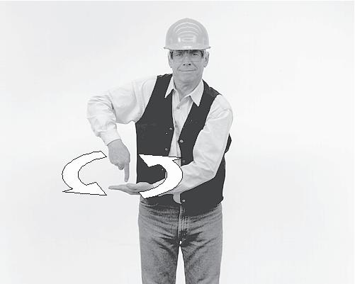

TURN MACHINE RIGHT SWING BLADE RIGHT To stop movement, stop moving hand and make a fist.
32
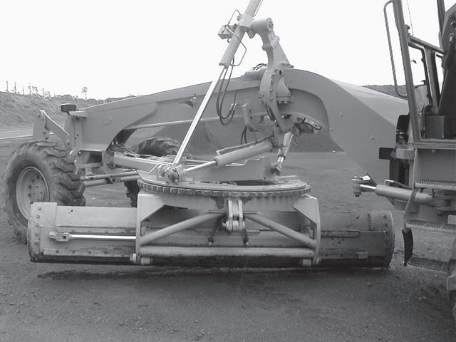
OPERATOR’S COMPARTMENT
WARNING: When the terms right and left are used in this manual, the reference point is the operator`s post (seat) in driving position, looking toward the front part of the machine.
Some of the following descriptions and instructions refer to optional items. Consult your CASE dealer with respect to the optional equipment available for your machine. To facilitate reading and learning about the instruments and controls of this machine, it has been separated in 6 groups, as shown in the figure. GROUP 1 Implement control levers (left side). Implement control levers (right side). GROUP 2 Steering wheel, console, pedals and hourmeter. GROUP 3 Dashboard, transmission control lever, throttle control lever, fuse box and master switch. GROUP 4 Operator’s seat and parking brake. GROUP 5 Cab
33
FRONT CONSOLE
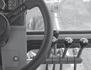
GROUP 1
Implement control levers (left side)
1 2

4
5
3
1. BLADE LIFT LEVER (LEFT END)
This lever is used to lower or raise the left end of the blade. Move the lever forward to lower or rearward to raise the blade. After reaching the desired height, release the lever to return it the neutral position.
2. FRONT SCARIFIER/BLADE OR RIPPER LEVER
This lever is used to lower or raise the front scarifier/blade or ripper. Move the lever forward to lower or rearward to raise. After reaching the desired height, release the lever to return it the neutral position.
3. BLADE SIDE SHIFT LEVER
This lever shifts the blade to the right or left. Push the lever forward to shift the blade to the left or pull it rearward to move the blade to the right. After shifting the blade to the desired position, release the lever to return it the neutral position.
4. BLADE PITCH LEVER
This lever allows the change of the blade pitch angle. Push the control lever forward (increase) or pull it rearward (decrease) until the desired pitch angle is achieved. Release the lever to return it the neutral position.
5. CIRCLE TURN LEVER
This lever is used to return the circle in clockwise or counterclockwise rotations. Push the lever forward to rotate counterclockwise or pull it rearward to rotate the circle clockwise. After moving the circle to the desired position, release the lever to return it the desired position.
Implement control levers (right side)
7
6 8 9
6. CIRCLE SIDE SHIFT LEVER
This lever is used to move the circle to the right or to the left. Move the lever forward to shift the circle to the left or rearward to shift the circle to the right. After moving the circle to the desired position, release the lever to return it to the neutral position.
7. ARTICULATION LEVER
Move the lever forward for left articulation or rearward for right articulation until the desired articulation angle is achieved. Release the lever to return it to the neutral position.
34
8. FRONT WHEEL LEAN LEVER
The front wheel lean lever leans the front wheels to the left or to the right to maintain stability when grading or ditching and to reduce turning radius. Move the lever forward to lean the wheels to the left or rearward to lean the wheels to the right. After reaching the desired position, release the lever to return it to the neutral position.
9. BLADE LIFT LEVER
This lever is used to lower or raise the right end of the blade. Move the lever forward to lower or rearward to raise the blade. After reaching the desired height, release the lever to return it to the neutral position.
10. WARNING FLASHER
10

GROUP 2
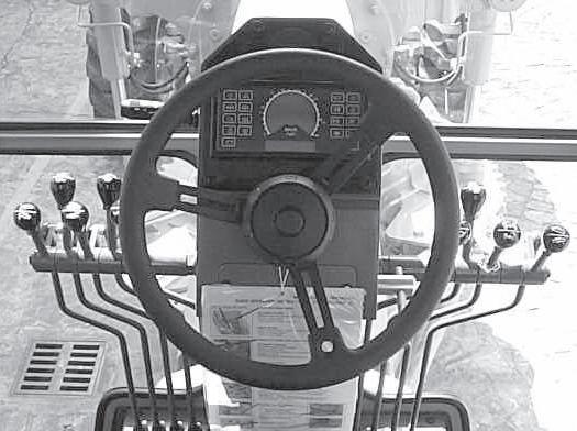
Steering wheel, console and pedals
1 4
5 7
3
2 6
1. FLOODLIGHTS, HEADLIGHTS LOW AND HIGH
BEAM, DIRECTIONAL LIGHTS AND HORN
LEVER 2. STEERING WHEEL 3. ELECTRONIC MONITOR, SPEEDOMETER,
HOURMETER AND ENGINE RPM DIGITAL
DISPLAYS 4. DIFFERENTIAL LOCK (OPTIONAL) 5. GEAR/ERROR DISPLAY 6. STEERING WHEEL TILT LEVER 7. HOURMETER
8. INCHING PEDAL 9. CONSOLE TILT PEDAL 10.BRAKE PEDAL 11.ACCELERATOR/DECELERATOR PEDAL
To activate the warning flasher press the button located on the right side of the front plastic console. To turn it off, press it once again.
8 9 10 11

35
1. FLOODLIGHTS, HEADLIGHTS LOW AND HIGH BEAM, TURNING SIGNALS AND HORN LEVER

To turn on the Parking Lights: rotate the light switch on the end of the directional signal lever one position. To turn on the Driving Lights: rotate the light switch on the end of the directional signal lever two positions.

To Operate the High and Low Beams: Move the lever up (vertically) one position (with the light switch rotated to the “ON” position) and the hibeam lights come on. Move the lever up (vertically) two positions (with the light switch rotated to the “ON” position) and the low-beam lights come on. Move the lever up (vertically) to the top momentary position and release the lever (with the light switch rotated to the “ON” position) and the hi-beam lights will flash and return to the lowbeam position. To sound the horn: push in on the end of the directional signal lever. To activate the right directional signal, push the directional signal lever away from the operator seat. To activate the left directional signal, pull the directional signal lever towards the operator seat.
2. STEERING WHEEL
The steering wheel is attached to an orbitrol steering control unit. The orbitrol is a combination valve and oil pump which is responsible for the supply of oil to the steering cylinder. The steering wheel may be tilted to achieve a better operator’s working position using steering wheel tilt lever.
36
3. ELECTRONIC MONITOR, SPEEDOMETER, HOURMETER AND ENGINE RPM DISPLAY DIGITALS
The control panel indicates any problem in machine function. For easy identification the signals are transmitted by activating a light emitting diode - LED. This electronic monitor permits the operator to monitor all the machine functions from the work station. FUNCTIONAL DESCRIPTION Electronic monitor check: 1. With engine shut-off and ignition key switch in the RUN position all the circuits are turned on.
The LED indicator lights flash in all functions for few seconds (test phase). IMPORTANT: When starting the engine and the key goes to START position the electronic monitor will turn OFF. Only the parking brake light will stay ON if activated. When the ignition key goes to run position the electronic monitor will do the check again.
2. After the test phase the following indicators will be turned off until the engine is kept turned off: • Low battery charge, E; • Low transmission oil pressure, F; • Low engine oil pressure, G; • Low brake oil pressure, H; • Parking brake, when the lever is pulled up, D.
All the LED’s indicators listed above will turn off except parking brake D (when activeted), and brake pressure H. 3. If any faults occur (for the functions described on this monitor), the corresponding LED light and the red warning light will flash followed by an audible warning (see item 4).
37
4. The following LED’s indicators do not activate the audible warning: • Parking brake, D; • Steering secondary (optional), P; • Differential lock , T; • General warning light, L; • High beam, N; • Turn signals, O and M. 5. Differential lock functions only with the parking brake disengaged and only in 1st to 7th gears. 6. Q - Speedometer registers the travel speed.
R - Indicates the engine RPM during operation.
S - Not available.
INSTRUMENT PANEL INDICATORS
A. ENGINE WATER TEMPERATURE When the light is ON, it means that the engine coolant has overheated which could be caused by: • Lack of coolant in the system • Radiator cooling fins clogged • Radiator circuit clogged • Fan hydraulic drive system malfunction • Defective thermostat. B. HYDRAULIC OIL TEMPERATURE When the light is ON, it means that the oil is overheated which could be caused by: • Use of oil with improper viscosity • Low oil level. C. TRANSMISSION OIL TEMPERATURE When the light is ON, it means that the oil is overheated and its probable causes are: • Suction line filter clogged • Low oil level • High oil level • Transmission hydraulic oil circuit troubles. D. PARKING BRAKE When the light is ON, it means that the brake is actuated. E. LOW BATTERY CHARGE When this light is ON, with the engine running, indicates defects in the charging system, caused by: • Defective alternator • Charging resistor damaged F. LOW TRANSMISSION OIL PRESSURE When the light is ON, this indicates insufficient oil pressure that may be caused by: • Use of oil with improper viscosity • Low transmission oil level • Defective switch and/or defective panel. G. LOW ENGINE OIL PRESSURE When the light is ON, this indicates insufficient oil pressure that may be caused by: • Use of oil with improper viscosity • Low engine oil level • Engine oil leak • Defective pressure switch
38
H. LOW BRAKE OIL PRESSURE When the light is ON, this indicates insufficient oil pressure that may be caused by: • Pump abnormalities • Air in the brake system • Oil leak on brake lines • Defective pressure switch. I. AIR FILTER RESTRICTION When the indicator remains on constantly, the air filter element is clogged and it will be necessary to clean or replace it. • Defective switch and/or defective panel. J. HYDRAULIC OIL FILTER RESTRICTION When the indicator remains on constantly, the oil filter element is clogged and it will be necessary to replace it. K. TRANSMISSION OIL FILTER
RESTRICTION When the indicator remains on constantly, the oil filter element is clogged and it will be necessary to replace it. L. WARNING FLASHER This indicator flashes when the button located on the right console is pressed in. M. RIGHT TURN SIGNAL N. HIGH BEAM O. LEFT TURN SIGNAL P. SECONDARY STEERING LIGHT (OPTIONAL) Not available.
4. DIFFERENTIAL LOCK SWITCH OPTIONAL
This switch is used to lock or unlock the differential when it is necessary. Use the differential lock switch only in straight line operation. To steer or articulate the machine the operator must turn off the differential lock switch. IMPORTANT: Do not turn off the differential lock system when the grader is operating.
5. GEAR AND ERROR CODE DISPLAY
This display shows the actual neutral, forward or reverse transmission gear selected. When an error occurs the display will flash an error code indicating that a problem has been detected in the system. When the ignition key is first turned on, the display will show three sets of double letters (TD DC ER) at the top and three 8’s. The first 8 will have a diagonal line through it. This is a system light check. If the key is left in this position without starting the engine, the display will next flash ER100 few times. This designates the revision version of the transmission’s computer software. There is also an error code ER100 but this error code only appears during recalibration. The revision code may change. The next code will be ER101, ER102, etc.
6. STEERING WHEEL TILT LEVER
Loosen the lever and adjust the steering wheel position to obtain more comfortable operating position. Tighten lever again to assure the steering wheel does not move.
7. HOURMETER
The hourmeter indicates operating hours with the engine off and key switch in the RUN position.
39
8. “INCHING” PEDAL
The “inching control pedal” is helpful under the following conditions: • When starting or stopping • For grader finishing work requiring “creeper gear” or very slow speeds • For very slow ground speed work to increase engine speed for hydraulic performance (this should rarely be necessary because of the wide range performance of the hydraulic system). CAUTION: Do not abruptly depress and release inching pedal to start a heavy load or free a stuck machine.
9. CONSOLE TILT PEDAL 10. BRAKE PEDAL
This pedal actuates the service brakes. To stop the grader press down on brake pedal. NOTE: Do not descend steep slope using only the service brake. Reduce the speed and apply the brakes. Select an appropriate speed, allowing total machine control. This will avoid brake heating, and will increase the life of the components.
11. ACCELERATOR/DECELERATOR PEDAL
The accelerator/decelerator pedal is connected to the engine throttle controls. To accelerate the engine, press down on the front part of the pedal and to decelerate press down on the rear of the pedal. When the pedal is released, the engine speed will return to the hand throttle setting.
The console may be adjusted to improve operator comfort. Push the pedal to free the console. Position the console in the desired position and then release the pedal to lock the console again.
40