3 minute read
Z-Bar Return To Dig Adjustment Procedure


TRIM THIS EDGE IMPORTANT: DO NOT turn the key switch to the OFF position if the machine is steered against either the right hand or left hand steering stop. The steering wheel may kick back. NOTE: The secondary pump/motor should not be run continuously for more than 20 seconds at a time without a 2 minute cool down. 6.Restart the engine to build up steering pressure. Confirm that the secondary steering lamp within the instrument cluster is illuminated and that the secondary and that the secondary steering pump / motor is running. The secondary steering pump / motor should stop after approximately 3 seconds and the secondary steering lamp should go OFF. 7.If steps 2 through 6 function properly, the secondary steering system is operating correctly. If not, repair the secondary steering system and then retest the system. 8.Start the engine and allow the batteries to recharge for a minimum of 10 minutes.
NOTE: The secondary steering system will only function as long as there is sufficient battery capacity.
PARKING BRAKE CHECK
NOTE: Test the parking brake at a maximum of 250 hours. Before you operate the machine periodically test the parking brake functions.
RD98K316
1.To release the park brake, all the following are required: A.Make sure that there is adequate service brake pressure. (Brake warning lamp is OFF)
212
TRIM THIS EDGE
Bur 6-36070EUR
LEFT PAGE
B.Push the Park Brake switch to the release position. C.Place the transmission shifter to
F or R to direct movement of the machine.
D.Place your foot on the service brake to gain control and release.
2.To engage the park brake, any of the following is required:
E.Loss of service brake pressure in both axles pressure circuits.
F.Loss of system electrical power (key OFF).
G.Placement of the Park Brake switch into the engaged position. 3.To test these functions:
A.Start the engine on a level flat surface, clear of other objects.
B.Perform Step 1, A through D.
Confirm that the Park Brake indicator lamp is OFF indicating the Park Brake is released.
C.Turn the key switch to the OFF position to stop the engine. After 5 seconds, turn the key switch to the ON position (not the START position). The Park Brake light should illuminate indicating the
Park Brake is engaged. D.Pump down the service brake pressure. Confirm the brake warning lamp is illuminated.
Continue to pump down the service brake pressure. Confirm that the Park Brake lamp is illuminated.
E.Start the engine and allow the brake pressure to build until the warning light goes out.
F.Depress the service brake and release. Confirm that the Park Brake lamp is illuminated. Put the transmission in F or R and back to N. Confirm that the Park Brake lamp is illuminated.
G.Place the park brake switch in the engaged position. Depress the service brake and put the transmission in F or R and back to N. Confirm that the Park Brake lamp is illuminated.
H.Place the park brake switch in the released position. Depress the service brake and put the transmission in F or R and back to N. Confirm that the Park Brake lamp is OFF. 4.Place the transmission in F and allow the machine to roll slowly forward. Place the Park Brake switch to the engaged position. The machine must come to a stop immediately. Confirm that the Park
Brake lamp is illuminated and that the transmission disengages. If all steps above perform as indicated, then the Park Brake system works correctly. If there was a problem with the test contact your dealer.
213
TRIM THIS EDGE
Bur 6-36070EUR
RIGHT PAGE TRIM THIS EDGE
LOADER ADJUSTMENTS
Height Control and Return To Travel Adjustment Procedure
2 6
TRIM THIS EDGE
5
1
3 4
BS00N076
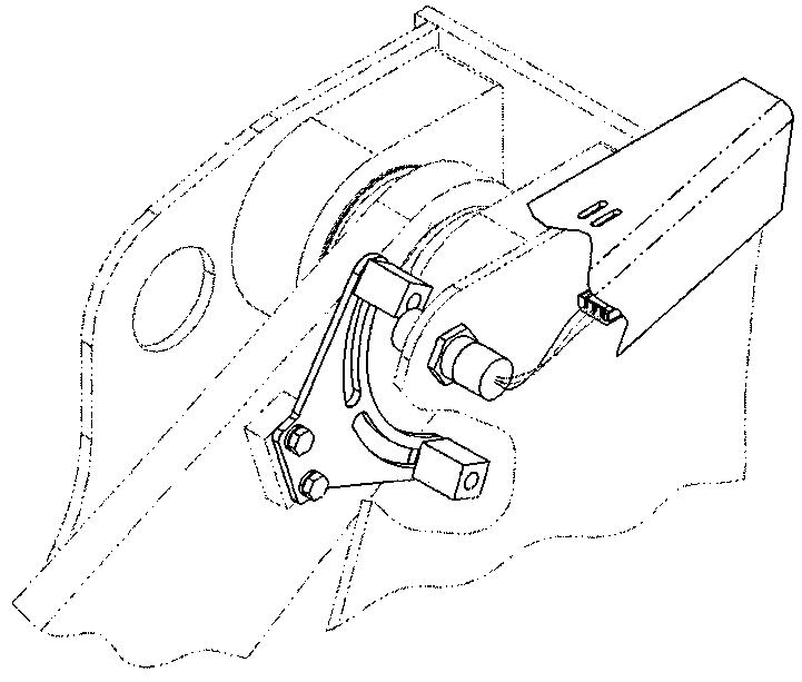
1.Proximity Switch 2.Return to Travel Target 3.Target Mounting Plate
4.Height Control Target 5.Lift Arm 6.Front Chassis (Top Left Hand Side) 1.To avoid damage to the proximity switch, it must be adjusted back, away from the lift arm, to clear everything on the lift arm as it sweeps past. 2.Start the engine. Position the bucket flat on the ground. Shut the machine off.
Locate the return to travel target opposite the proximity switch and then tighten it to the target mounting plate. Next adjust the proximity switch out toward the target until and air gap of 3.5 to 5.0 mm (1/8 to 3/16 inch) is obtained. Lock the proximity switch in position with its jam nut. Torque the jam nut to 5 ft.lbs.
214
TRIM THIS EDGE
Bur 6-36070EUR
LEFT PAGE