2 minute read
ACCESS DOORS


TRIM THIS EDGE
LOWERING THE OPERATOR’S COMPARTMENT INTO THE OPERATING POSITION
1.Make sure all tools or other items have been removed from the interior of the chassis before the operator’s compartment is lowered.
1
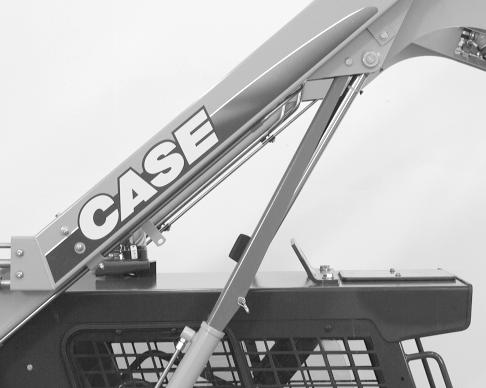
BD04N097 2.Release the cab hold open latch by pushing the lever (1) forward.
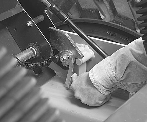
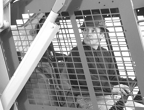
BD05A062 3.Gripping both front cab hand holds near the top, slowly lower the cab into operating position. IMPORTANT: On pilot models use caution when closing ROPS to ensure the pilot control handles do not get caught on the ROPS seat plate.
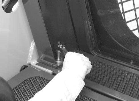
BD01C171 4.Install and tighten the operator’s compartment mounting bolts to torque of 180 to 320 Nm (130 to 235 pound-feet).
1
3
2
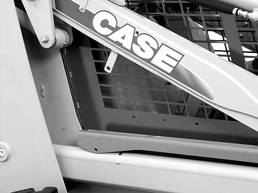
BD01C142 5.Raise the loader lift arms and remove the pin (2) from the loader lift arm support strut (1). Place the loader lift arm in the storage position and install the pin (2). See
Storing the Support Strut on page 110. 6.Before operating the skid steer make sure the operator’s compartment is fully lowered and the mounting bolts are installed and tightened.
108
TRIM THIS EDGE
LEFT PAGE
Bur 87592047na
INSTALLING THE SUPPORT STRUT
WARNING: If you service the machine with the loader lift arms raised, always use the cylinder lock support strut to block up the loader lift arms. Failure to follow this procedure can cause serious injury or death if the loader lift arms are lowered by accident.
SC018
IMPORTANT: Installing the Support Strut can be performed as a one or two person procedure so that the operator is not exiting the operator’s compartment under unsupported loader lift arms. Remove the attachment from the loader lift arms before starting this procedure.
IMPORTANT: Before exiting a machine with the lift arm up, engage the support strut:
1.While sitting in the operator’s seat with the seat bar down lower the loader lift arms to the ground and stop the engine.
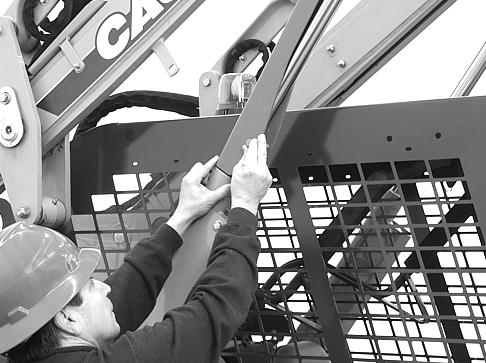
BDO4M021 4.Start the engine and slowly raise the loader lift arms until the support strut is on the lift cylinder rod.
Lower the loader lift arms until the support strut makes contact with the lift cylinder tube. Stop the engine.
BD04M022 2.Remove the pin from the support strut. 3.After the pin is removed, lower the support strut onto the lift cylinder.
BD04M023
5.Install the pin in the support strut.
109
TRIM THIS EDGE
RIGHT PAGE
Bur 87592047na TRIM THIS EDGE