18 minute read
Identification of Controls ..................................... 12 thru


CONTROLS - IDENTIFICATION
Figure 5. Instrument Panei
14
.INSTRUMENT PANEL IN OPERATOR'S CAB.
1. KEY SWITCH - Turn Switch clockwise to energize the electrical system. Switch must be ON before starter button will crank the engine. 2. BRAKE "ON" WARNING LIGHT - With Key Switch ON, this red light warns the Operator that the Track Brake is APPLIED.
3. ENGINE SHUTOFF CONTROL - (CASE engine only) - To shut down the CASE engine, pull up on the Shutoff Control Handle until the engine stops. This control shuts off the flow of fuel into the engine intake manifold.
NOTE: The Throttle control is used to shut off the engine on machines equipped with Detroit Diesel 4-71 engines. Refer to Item 14, Figure 5.
4. AMMETER - Indicates the amount of charge the Batteries are receiving.
A steady reading of 0 to 5 amps is normal.
5. ENGINE COOLANT TEMPERATURE GAUGE - Indicates the temperature of the engine coolant. Needle should stabilize between 1800 F. - 1900 F. (820 C - 880 C.) when fully warmed and operating.
6. PANEL LIGHTS SWITCH - Turns on the two instrument panel lights for night operations.
7. HEATER CONTROL -Turn the Control clockwise to increase the amount of heat coming from the Heater in the rear of the cab; turn counterclockwise to decrease heat. Turn all the way counterclockwise to turn the Heater OFF.
8. PARKING BRAKE CONTROL - Pull up on the Control to APPLY the Track brakes; to release the Brakes, push control DOWN, then engage either Left Track, Hoist/Utility or Tool Control to pressurize brake
circuit and release the brakes.
15
CONTROLS - IDENTIFICATION
INSTRUMENT PANEL CONTROLS (CON'T.)
9. LIGHT SWITCH - Turns on the work iights on cab and boom.
10. COLD START BUTTON - Used to help starting during cold weather.
When Button is pressed, a small amount of starting fluid is discharged into the intake manifold. A thermostat, mounted on the engine, prevents the injection of fluid into a hot engine.
11. OIL PRESSURE GAUGE - Indicates engine oil pressure. Normal oil pressure for the DETROIT DIESEL engine is 35-50 psi (241-345 kPa); for the CASE engine, 45-60 psi (310-414 kPa). NOTE: Gauge may not return to zero during shutoff period.
12. FUEL GAUGE - Indicates the amount of fuel in the fuel tank.
13. HORN BUTTON - Sounds the vehicle horn when pressed.
14. THROTTLE CONTROL - Controls engine speed. Also controls engine shutdown on units equipped with Detroit Diesel 4-71 engines. Push forward to increase engine rpm; pull back to decrease rpm. To shu t off the Detroit Diesel engine, pull Throttle all the way back.
15. HOURMETER - Indicates total engine operating time. Starts running when the engine starts. Use this instrument, along with a calendar, to carry out the SCHEDULED PREVENTIVE MAINTENANCE Program on your machine.
16. STARTER BUTTON - Energizes the Starter Motor to crank the engine.
17. PANEL LIGHTS - Illuminate the Instrument Panel for night operations.
18. DRIVE RANGE SWITCH - (Optional) - Controls High-Low range on machines with two-speed hydraulic drive motors.
16
ELECTRICAL CIRCUIT PROTECTION
The Logger is protected against electrical overload by four fuses,
located on a fuse block in the Instrument Panel. Figure 6 illustrates components and systems protected by these fuses.
The Fan is protected by an additional in-line fuse, in the wire from the Fan Switch. If optional Work Lights are installed on the machine, this circuit will also include an in-line fuse.
G 0
0
caJ 15 AMP
I 15AMP -
I
Il«fl - 7.5 AMP
10 0 0 HORN, COLLECTOR (OPT.), ROTARY CUTTER (OPT.)
D EFROSTER FAN,
WIPER, PANEL LIGHTS, COLD
WEATHER START I-BR ARE ON WARNING LIGHT, OIL
ESSURE PR GAUGE, FUEL GAUGE -
GINE EN TEMP. GAUGE
HOURMETER
Figure 6. Cab Fuse Block
A circuit breaker is also included in the Instrument Panel. If it fails to reset automatically, it must be replaced.

17
OPERATING INSTRUCTIONS
This section contains the information necessary to correctly operate the LOGGER. Included are (1) starting the engine, (2) driving the LOGGER, (3) using the Feller-Buncher and (4) general operating instructions.
DELIVERY INSPECTION
The LOGGER has been serviced and tested at the factory. As an added precaution, perform the checks listed in the Preventive Maintenance Schedule (page 48) before operating the machine.
ABefore starting the engine make sure all operating controls .. are in NEUTRAL.
STARTING THE ENGINE
Apply track brake. Push Engine Shutoff Control down and set throttle 1/4 open. Turn on the key switch and depress starter button. Do not exceed 30 seconds cranking time as heat damage to Starter could result. When engine starts, release starter button.
COLD WEATHER STARTING
Pull the Engine Shutoff Control out. Turn the Key Switch ON and crank the engine to warm the pistons. Then push the Engine Shutoff Control in, set throttle 1/4 open and again crank the engine. If engine fails to start, press the Cold Start Button, then again crank the engine.

NOTE: A metered amount of starting fluid is injected into the engine each time the Cold Start Button is depressed. The button should not be depressed
more than once during start-up, as engine may become vapor-locked.
Let the engine warm up to normal operating temperatures before using the machine. Check all gauges for proper reading. Approach full working
capacity gradually to allow the hydraulic oil to warm up.
USING BOOSTER BATTERIES
The engine in this machine cannot be started by towing or pushing. The following procedure must be used to start the engine if the Batteries are
discharged. Both the booster and the discharged Batteries should be treated carefully when using jumper cables.
18
A
WARNING: BATTERIES PRODUCE EXPLOSIVE GASES.
Keep flames, sparks and cigarettes away. Venti)ate when charging or using in enclosed space. Always shield eyes when working near batteries.
1. Make sure the Track Brake is APPLIED and that all controls are in
NEUfRAL. Turn off all electrical loads.
2. Remove vent caps from both the booster and discharged batteries. This .... will reduce the .hazard of explosion always present in either .hattery
when connecting the "live" battery to "dead" batteries.
3. Disconnect the Alterhator FIELD connection. See Figure 7.
e __
FIELD CONNECTION
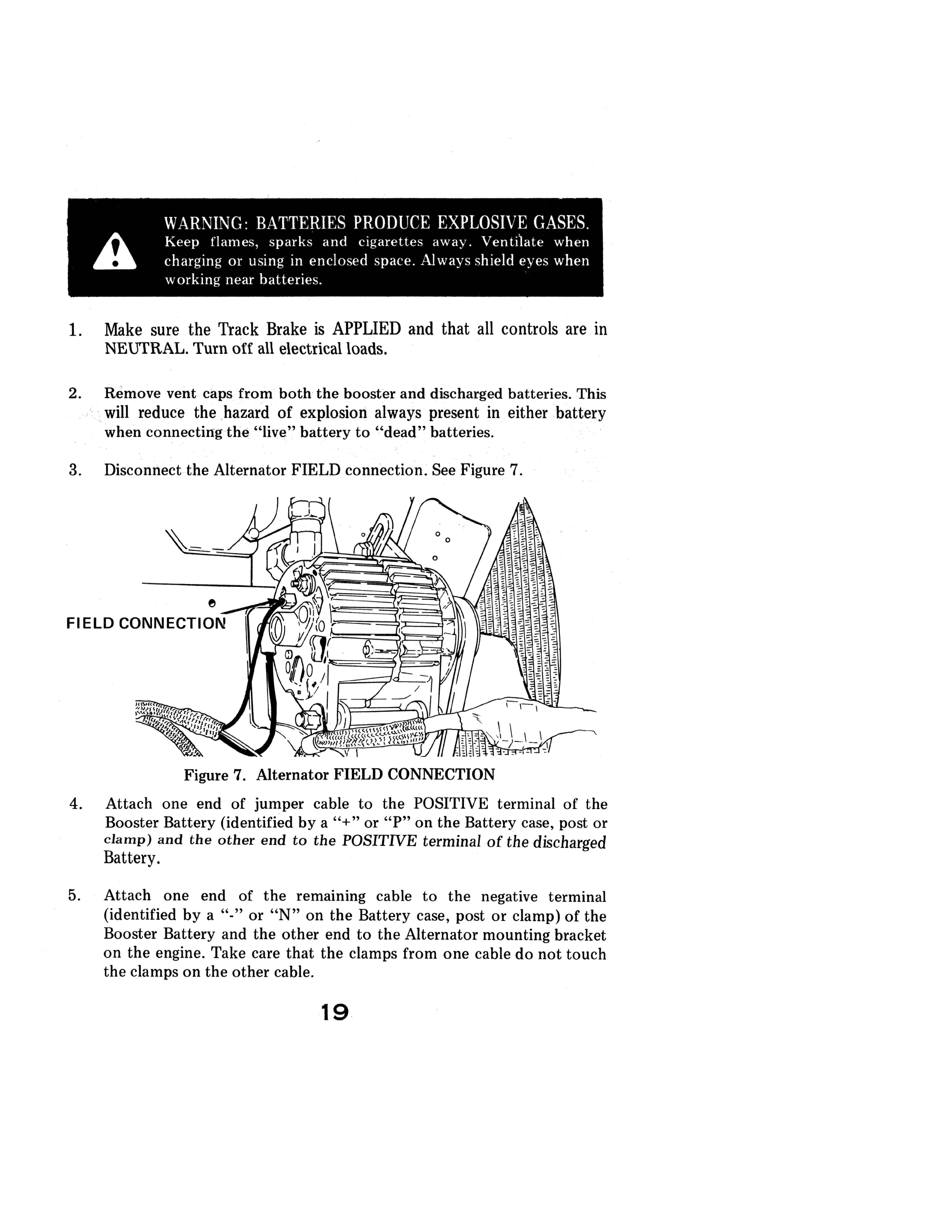
Figure 7. Alternator FIELD CONNECTION 4. Attach one end of jumper cable to the POSITIVE terminal of the
Booster Battery (identified by a "+" or "P" on the Battery case, post or clamp) and the other end to the POSITNE terminal of the discharged
Battery.
5. Attach one end of the remammg cable to the negative terminal (identified by a "0" or "N" on the Battery case, post or clamp) of the
Booster Battery and the other end to the Alternator mounting bracket on the engine. Take care that the clamps from one cable do not touch the clamps on the other cable.
19
OPERATING INSTRUCTIONS
AWARNINC: Rpcaus(' of prpspnt \dwn ('Ol1l1p('llI1g thl' 1i\1' dangt'r of batleries pxploslon ,d\\.t\, 10 dpad hdltl'rJ!'s,
.. \;EYER 11'.t11 O\l'r h.tIII'r1I'S \\ Ill'll ('Olllll'('llllg 11l1l11wr (dbl!',
6. Reverse this sequence, exactly when removing the" j\lmper) oables>,
Reinstall vent caps', and, throw wiping cloths away, as,they; might! halliecorrosive add] on, them. Reconneet. the, Alternator, FIELD: connection; only AF1:ER?the jumper cables,have been removed.
W \/{,\:I\C, Do \;OT allow halter\' tlulo l O l'()lllac t eyes, fahri(, or paintPfj surf,!('ps, Bat (pry fluid is a sulfuric acid solution which could cause serious Injury or properlY damage
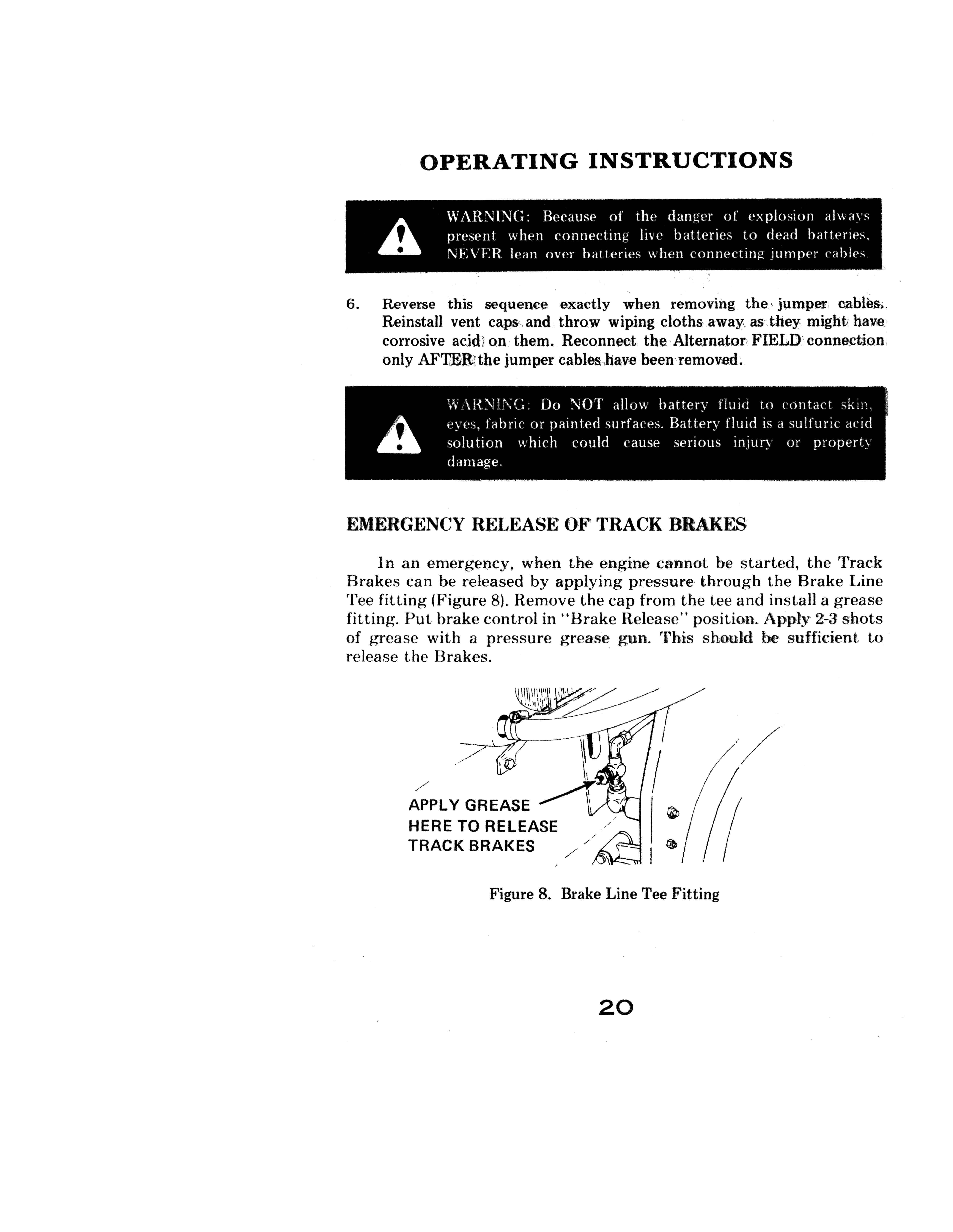
EMERGENCY RELEASE OF' TRACK BRAKES
In an emergency. when the engine cannot be started. the Track Brakes can be released by applying pressure through the Brake Line Tee fitting (Figure 8). Remove the cap from the tee and install a grease fitting. Put brake control in "Brake Release" position. Apply 2-3 shots of grease with a pressure grease gun. This should he sufficient to release the Brakes .
./ APPLY GREASE HERE TO RELEASE TRACK BRAKES ./
Figure 8. Brake Line Tee Fitting
20
STOPPING THE ENGINE
NOTE: Before stopping engine, idle it for a few minutes to allow engine and hydraulic components to cool gradually.
To shut off the CASE engine, pull Engine Shutoff Control OUT. To shut off the DETROIT DIESEL engine, pull Throttle all the way back. Turn off the Key Switch and all electrical equipment to prevent battery drain.
MACHINE SHUT DOWN
At end of work, park on firm, level surface. Place FellerlBuncher firmly on ground. Lift one side at a time and spin tracks to clean. Place all controls in neutral, then shut down the engine and turn key switch OFF. Lock the cab and close all compartment doors. If freezing conditions exist, park the machine on planks.
DRIVING THE LOGGER
Correct Travel position is with the front of the Turntable over the front of the Undercarriage. The Boom should be crowded in and the FelIer/Buncher head level or tilted back. Track Idler Wheel should be to the front, Drive Sprockets to the rear. See Figure 9. Apply the House Brake to keep the turntable from drifting.

Figure 9. Travel Position
TRACK DRIVES TO THE REAR
21
OPERATING INSTRUCTIONS
DRIVING THE LOGGER (CON'T.)
1. Start the engine. Refer to STARTING THE ENGINE, Page 16.
2. To travel forward: Set the Throttle Control to the desired setting.
Release the Track Brake and press both Drive Pedals down with the toe.
Use the Drive Pedals to vary the Crawler speed. To stop the machine, slowly return Pedals to neutral, move throttle control back to idle.
After stopping, apply the track brakes.
Machines with PIN 450 through 6275248 have track drive detents. To travel over a distance, press both Drive Pedals down and pull the Detent Control Handle UP to lock the Drive Pedals at full forward. Turns can be made with Detent engaged. To release the Track Detent Control, push the handle DOWN.
3. To travel rearward: The Detent Control Handle will not lock the Drive
Pedals in REVERSE. Release the Track Brake, Set throttle control and push Drive Pedals down with the heel. Slow or stop the machine in the same manner as when traveling forward.
NOTE: Never drive over stumps or other objects with the Drive Sprocket forward. This could transmit extreme shock loads into the Final Drive Transmission and cause early failure. If you must travel over stumps, drive with the Idler Sprocket to the front.

4. When turning the LOGGER maintain pressure on both Drive
Motors. For example, when turning left, fully depress the Right
Drive Pedal while maintaining slight pressure on the Left Drive
Pedal to keep both track motors working. A VOID ROCKING
THE PEDALS BACK AND FORTH. On machines with twospeed drives, put the drive range switch to LOW range to get full power when making a turn.
The Control Pedal on the extreme left controls left track. To drive the left track forward, depress the pedal with the toe (Figure 10, Item 1).
To drive the left track rearward, depress the Left Track Drive Pedal with the heel (Figure 10, Item 2).
22
DRIVING THE LOGGER (CON'T.)
!-''!i
" I Ii " Ii ),
" ,I " II ,I Ii I' i; I:: I [1 ()
, '" I I
i!il ,,!,:l
Figure 10. Left Track Control
Figure 11. Right Track Control

The Control Pedal on the extreme right controls the right track. To drive the right track forward, depress the pedal with the toe (Figure 11, Item 1).
To Drive the Right Track in REVERSE, depress the RIGHT TRACK DRIVE PEDAL with the heel (Figure 11, Item 2).
23
OPERATING INSTRUCTIONS
USING THE WORK FUNCTIONS
The following pages explain the operation of the Work functions Swing, Crowd, Tool, Leveler and Hoist/Utility. Use "feathering" technique to vary work speed and maintain functional controL
Avoid jerky and abrupt control engagement. Such a method of operation may look flashy, but is inefficient and hard on machine components. Do not use Throttle as substitute for "feathering" technique.
Before attempting to cut trees, study the individual work functions carefully. Practice to develop coordination so that you can lower the Hoist, Crowd out, and actuate the Tool Cylinder to keep the Feller/Buncher vertical. Then reverse this sequence, Swinging and opening the Shear Arms at the same time. Perform these functions at no more than half throttle at first. Gradually increase the speed. As the sequences become mastered you will sOon be ready to cut trees at full speed.

The function of the Swing and Crowd controls can be interchanged on the LOGGER. Before working the machine, check the use of each control in a safe area. If the Swing and Crowd controls are interchanged, a new OPERATOR'S CONTROL DECAL must be installed in the cab at the time of the change. See page 40 for the correct procedure for interchanging the controls.
24
USING THE LEVELER CONTROL
The Turntable can be tilted up to 8-1/2° to help level the Feller/Buncher.
Standard gauge units are equipped with two Leveler Cylinders; Wide gauge units have four. NOTE: On earlier units, leveler locks are installed on the leveler base. When shipping the machine, these Locks should be placed under the
leveler ears. Before operating the machine, make sure the Locks are swung out from under the ears and held securely in place by their springs. On units without leveler IOGks, use a block of wood, under the leveler ears to keep the upperstructure level during transport. .
To tilt the Turntableto the right (Item 1, Figure 12), push the Control Handle forward. ,. .
To tilt the Turntable to the left, (Item 2, Figure 12), pull the Control Handle back.
Figure 12. Leveler Control
25

OPERATING INSTRUCTIONS
USING THE SWING CONTROL
AWARNING: Before swinging, . check area around the machine for people or objects wlthm range of the Feller/Buncher or the cut tree as it is dropped.
Always start and stop Turntable rotation with a smooth, feathering motion of the control. The House Brake Control Handle should be used as a holding brake only. Never use it to stop Turntable rotation, except in an emergency.
L"i.. WARNING : CROWD INTERCHANGEABLE. AND SWING THEREFORE CONTROLS THE OPER. .\RE \ TOR .. (REGARDLESS OF EXPERIENCE) :\ll'ST CHECK CONTROLS PRIOR TO OPERATION.
Figure 13. Swing Right/Left Operation
To swing left (Item 2, Figure 13), press the Swing Pedal down with the heel.
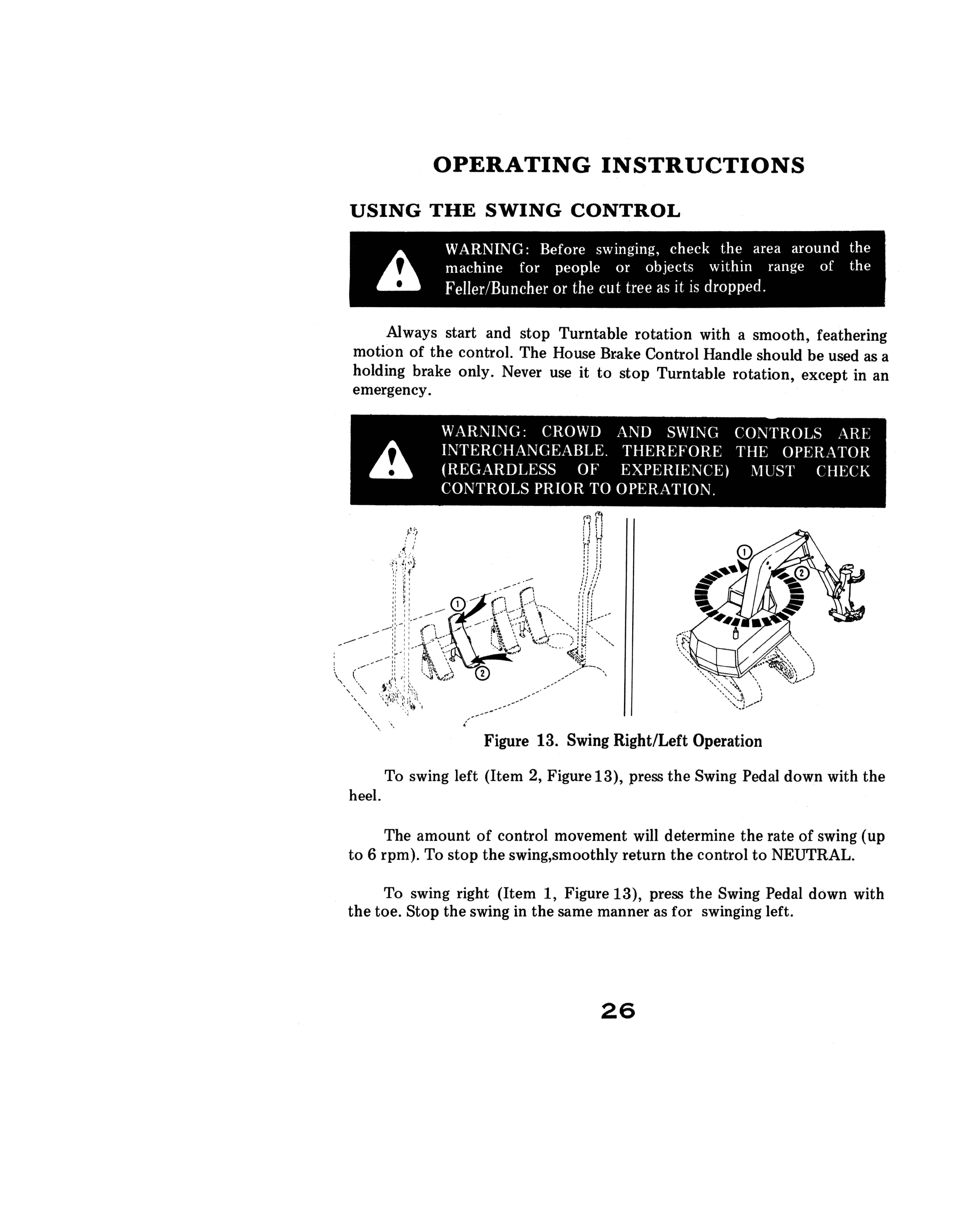
The amount of control movement will determine the rate of swing (up to 6 rpm). To stop the swing,smoothly return the control to NEUTRAL.
To swing right (Item 1, Figure 13), press the Swing Pedal down with the toe. Stop the swing in the same manner as for swinging left.
26
USING THE CROWD CONTROL
To crowd the boom out (Item 1, Figure 14); move the Crowd Handle forward. Use a smooth, continuous (feathering) motion until the desired
Crowd speed is reached. To crowd the boom in (Item 2, Figure 14), move the Crowd Handle rearward. Use a smooth, continuous motion, as before.
Figure 14. Crowd Control
USING THE TOOL CONTROL
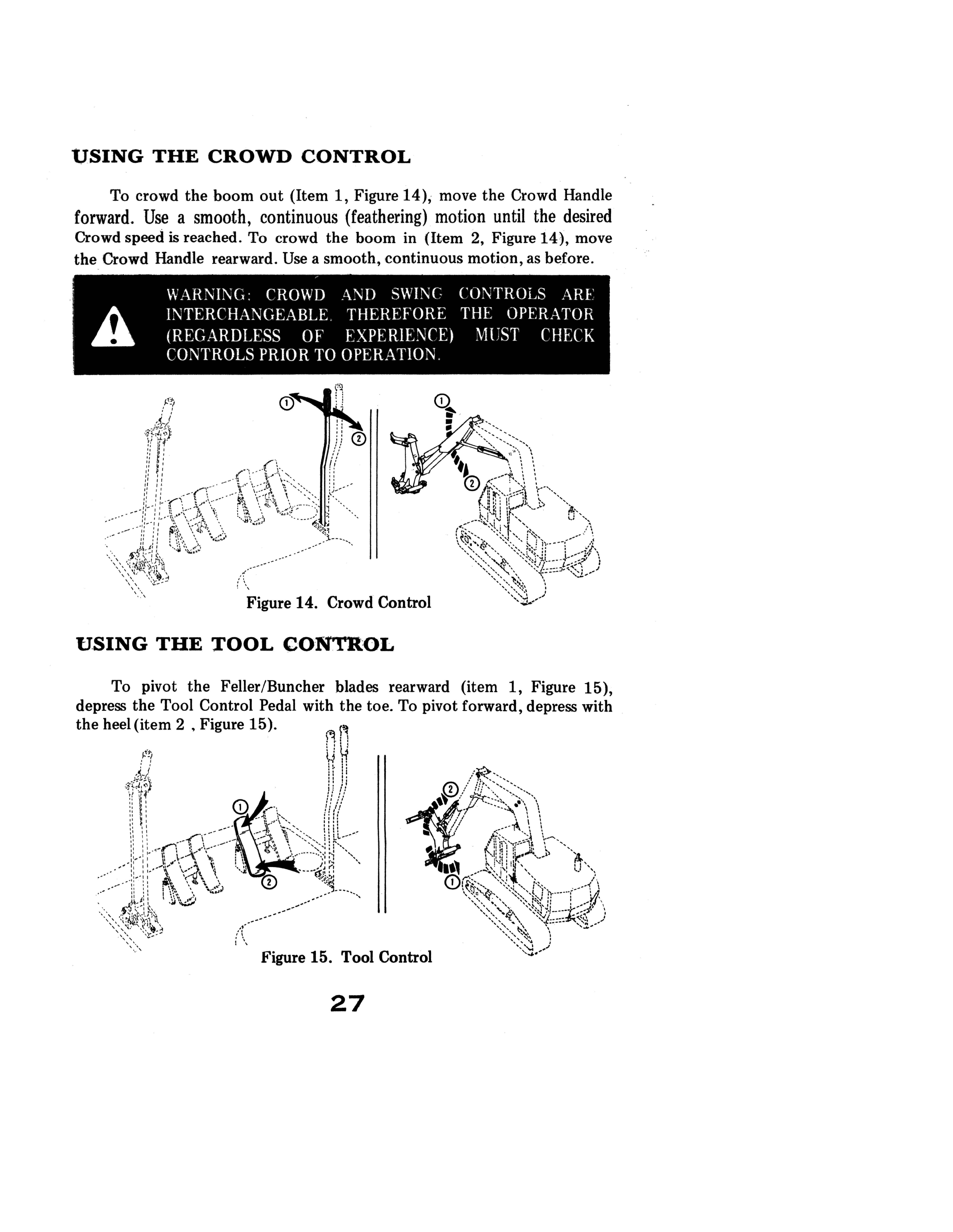
To pivot the Feller/Buncher blades rearward (item 1, Figure 15), depress the Tool Control Pedal with the toe. To pivot forward, depress with the heel (item 2 • Figure 15).
,..r
i\
Figure 15. Tool Control
27
OPERATING INSTRUCTIONS
OPERATING THE HOIST/UTILITY CONTROL
To hoist UP (Item 2, Figure 16), pull the Hoist/UtilityControl Handle back. Use a smooth, continuous motion until the desired hoisting speed is reached. To hoist DOWN (Item 1,Figure 16), move the Control forward.
Figure 16. Hoist Up/Down Operation
To OPEN the Feller/Buncher Shear Arms (Item 2, Figure 17), move the Hoist/Utility Control Handle to the Left.

To CLOSE the Shear Arms (Item 1, Figure 17), move the Handle to the right.
Figure 17. Shear Arm Con trot
28
OPERATING THE FELLER-BUNCHER
NOTE: Before attempting to cut trees, study USING THE WORK FUNCTIONS carefully. Then practice coordinated use of work functions as described on Page 24.
Kno\\ you r Feller! Bun cher capac it ies. Refer to SPECIFICATIONS. page 11, for maximum tree diameter and weights. The Feller!Buncher is designed to handle a maximum sized tree at IT radius.
NOTE: Always ensure that Cab Guards are in place during operation.
Planning the Job
Before starting work, study the ground conditions, terrain and type of timber stand to be cut. Then plan your work based on the conditions found. The following rules apply:
1. For maximum efficiency, keep swing arc as short as possible, preferably within 900 , depending on the work situation.
2. Cut (or knock down) dead trees and stubs to prevent accidents.
WARNING: HANDLE DEAD TREES WITH EXTREME CARE. Keep them leaning forward to keep tops from falling onto the machine. Bumping dead trees from the side will normally make the tops fall sideways, away from the machine.
3. It is best to work along the face of timber stand, laying the trees in a
herringbone pattern out into the open with the butts close together and the tops fanned out as shown in Figure 18. This will allow room for limbing and toppinI!'. The width of cut (up to 52') is governed by the room you have to lay the trees down.
29
OPERATING INSTRUCTIONS
Figure 18. Working Along the Face of a Timber Stand
4. The machine can work in a large circle or around a square with the limbers and skidders at a safe distance behind it. They will clean out the fallen timber to keep it from getting covered up on the next pass.

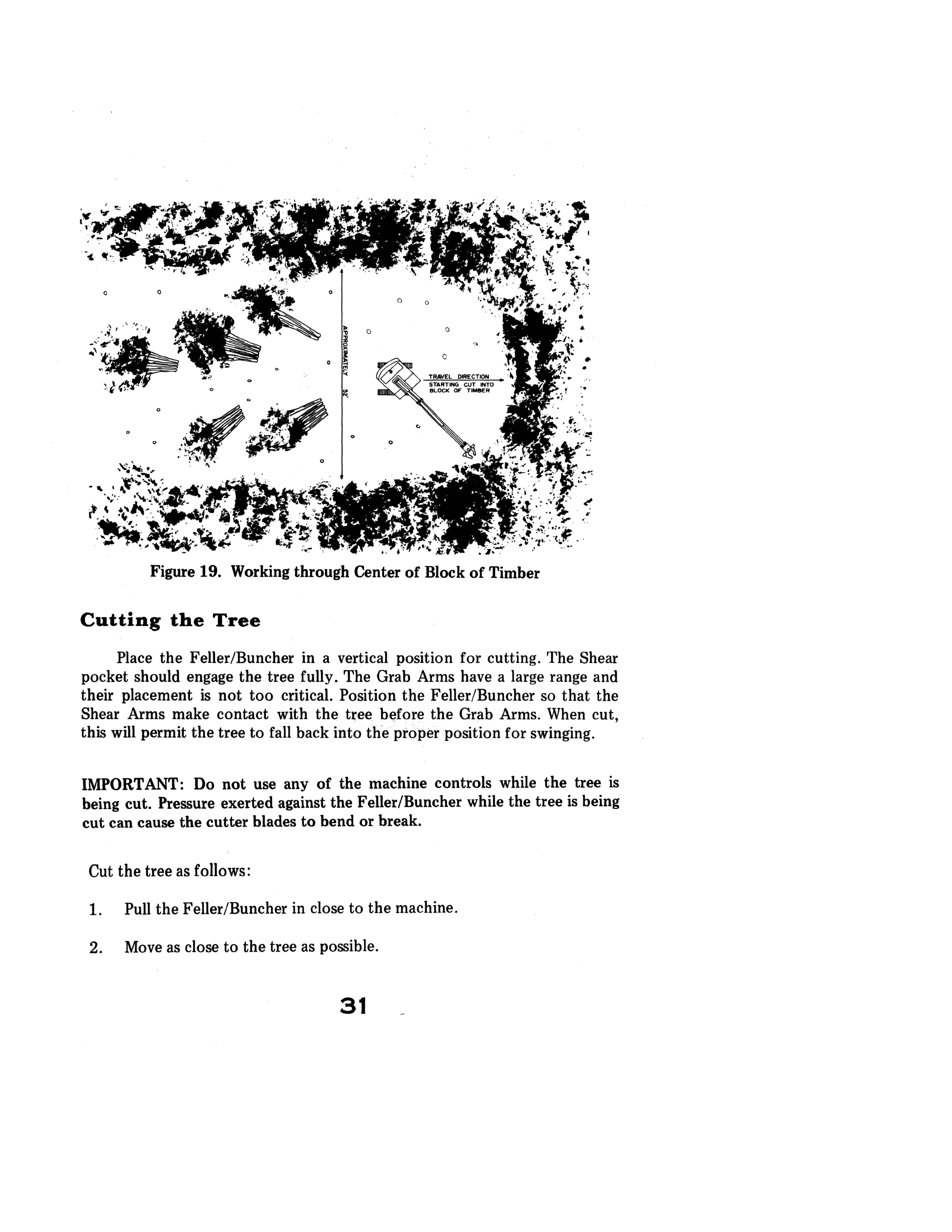
5. When starting into the center of a block of timber, cut as wide a strip as possible. Lay the trees down behind the machine in a herringbone pattern to prevent covering up any trees. The machine may have to
come back without cutting to start the next strip, after the first trees are cleaned up. (Refer to Figure 19).
30
Figure 19. Working through Center of Block of Timber
Cutting the Tree
Place the Feller/Buncher in a vertical position for cutting. The Shear pocket should engage the tree fully. The Grab Arms have a large range and their placement is not too critical. Position the Feller/Buncher so that the Shear Arms make contact with the tree bElfore the Grab Arms. When cut, this will permit the tree to fall back into the proper position for swinging.
IMPORTANT: Do not use any of the machine controls while the tree is being cut. Pressure exerted against the FeIler/Buncher while the tree is being cut can cause the cutter blades to bend or break.
Cut the tree as follows:
2. Move as close to the tree as possible.
31
OPERATING INSTRUCTIONS
CUTTING THE TREE (CON'T.)
3. Place the shear firmly against the tree. Then close the shear arms. The knives should cut through the entire tree. If they do not, blade adjustment may be necessary. NOTE: "Racking" of Feller/Buncher to break tree off at stump is not With proper shear knife adjustment, the tree will be cut off
completely.
Figure 20. Proper Position for Cutting

Unloading and Piling the Tree
Mter the tree is cut use the following procedure:
1. Use the Crowd, Hoist and Tool functions to bring the tree in close to the machine. The tree should be in a vertical position, leaning slightly
toward but not over the Cab. See Figure 21.
2. Swing the tree into position for unloading. Tilt the head forward to start the tree falling. Release the tree BEFORE it hits the ground. This is easier on the machine and Operator, increases productivity, and smashes the branches to allow stacking more trees in a pile. (Refer to
Figure 22).
32
Figure 21. Tree Position After Cutting

3. Avoid entangling sheared trees in the tops of standing trees. This can be prevented by shearing trees closest to where they will be bunched.
4. Lay the first trees that are cut close to the machine at a 90° angle, or
off to one side. This will put more trees in one place for increased skidder production.
5. Try to lay tree butts on a windfall or knoll to help the choker setter pick up the bunch.
33
OPERATING INSTRUCTIONS
FELLER/BUNCHER· COLLECTOR (OPTIONAL)
The Collector Arm is designed to close whenever the Feller/Buncher shear/grab arms are operated (either opening or closing). Once the collector arm is closed, it will remain "closed" until the button (collector control switch) on the shear/grab control lever is pressed. When the collector control switch is pressed, with the Feller/Buncher operated, the collector arm will open.
COLLECTOR CONTROL VALVES
Figure 23. Feller/Buncher with Collector