
5 minute read
API gravity, minimum Flash point, minimum ........................................................................................................................60° C (140° F) Cloud point (wax appearance point), maximum .......................................................-20° C (-5° F) See Note above Pour point, maximum ..............................................................................................-26° C (-15° F) See Note above Viscosity, at 88° C (100° F)
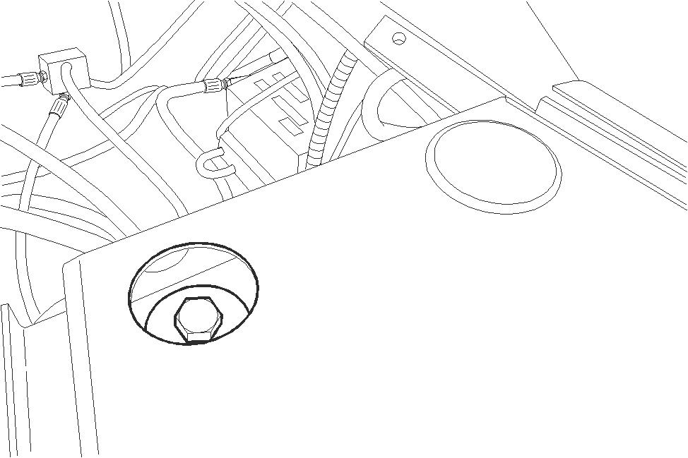
BD07G158-01 Remove the two plugs, remove the hood front mounting bolts.
STEP 9
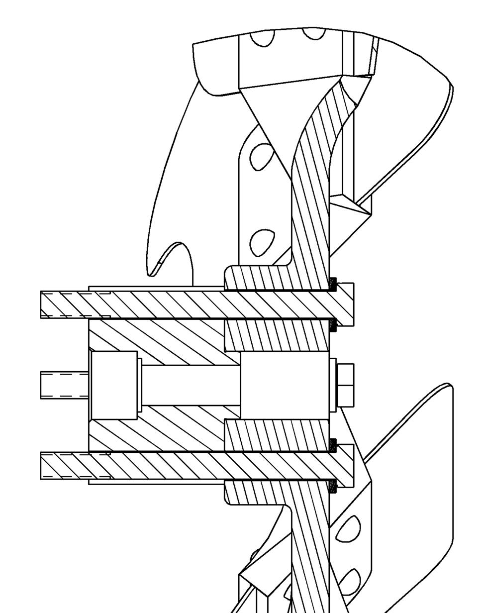
BD07F128-01 Remove the two plugs, remove the hood rear mounting bolts.
STEP 10
Attach lifting equipment to the hood, remove the hood from the machine.
STEP 11
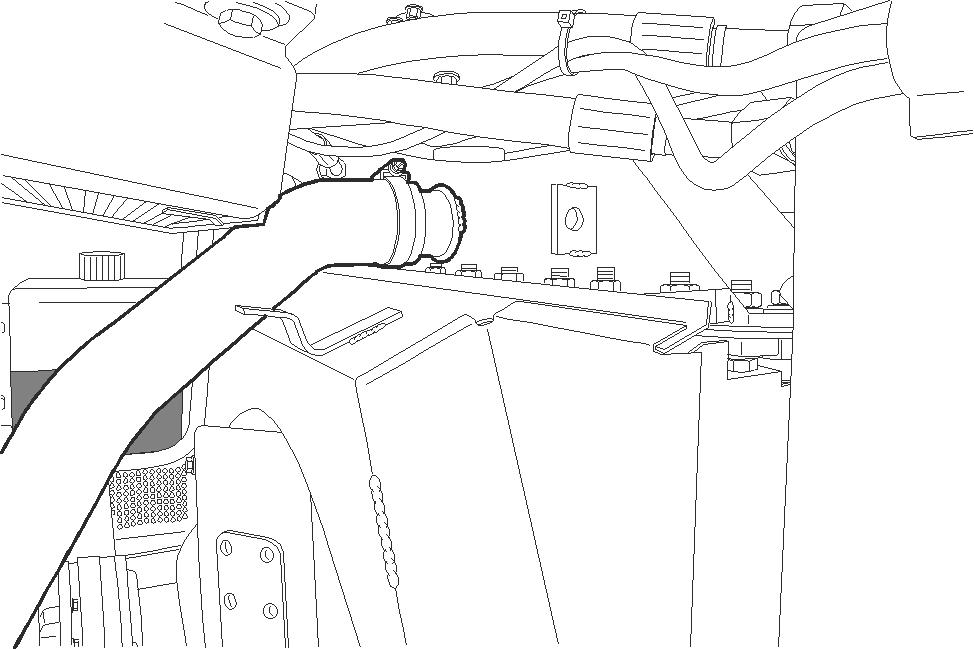
BD07H108-01 BD07H107-01
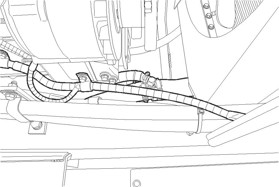
Disconnect the lower radiator hose.
STEP 13
1 2
1.SPACER 2.FAN MOUNTING BOLTS (4)
BS07H289-01
Remove the fan and spacer from the engine.
STEP 14
Tilt the ROPS cab or canopy, see section 9008.
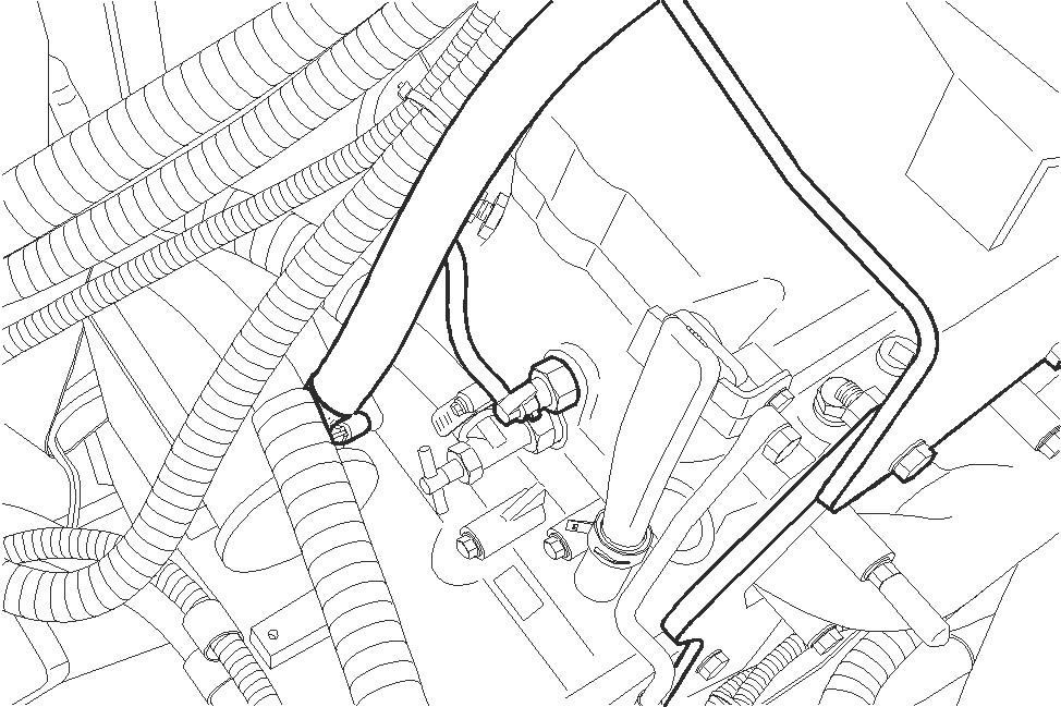
BD07F127-01 If machine is equipped with a heater, loosen the clamp and disconnect heater hose.
STEP 16
Disconnect the wires from the alternator.
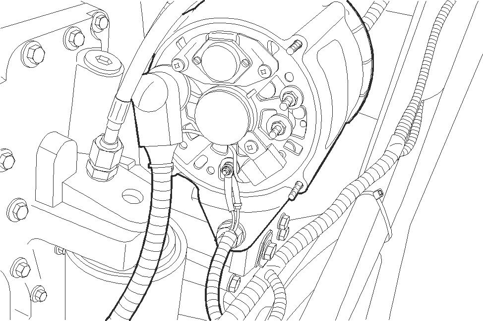
BD07F130-01
STEP 17
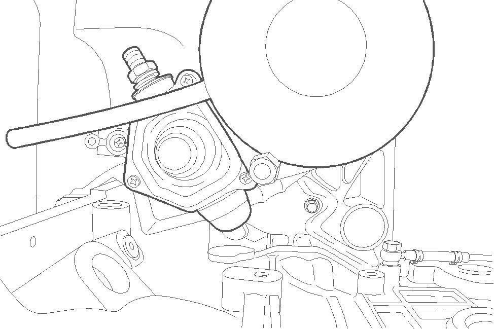
BD05H103-01 Disconnect the battery cable and the wiring harness wires from the starter.
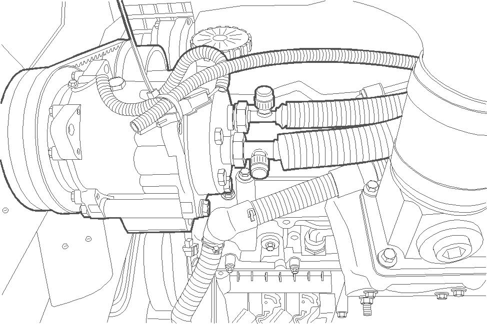
BD05H172-01 If equipped, discharge the air conditioning system, see section 9004. Disconnect the electrical connector for the clutch and the compressor hoses. Plug the hoses and cap the fittings.
STEP 19

BD07F138-01 Disconnect the electrical connector from the engine controller.
STEP 20
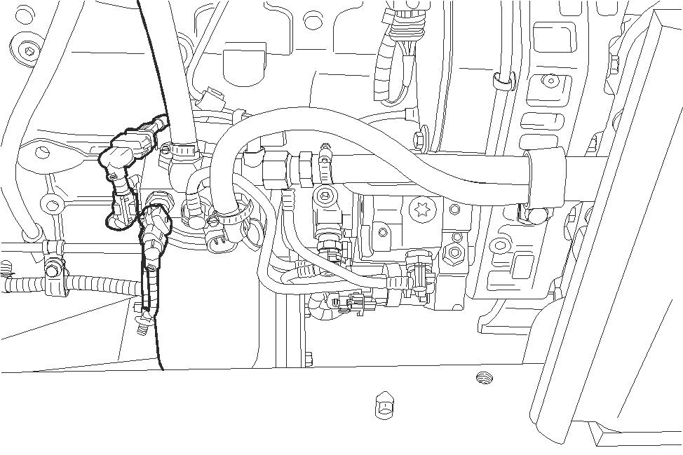
BD07F097-01 Connect a vacuum pump to the fuel tank, turn on the pump. Disconnect the fuel lines. Plug the lines and cap the fittings, turn off the vacuum pump.
Disconnect grounding cable from the bell housing.
STEP 22
Attach lifting equipment to the engine.
STEP 23
Remove the engine mounting bolts.
STEP 24
Raise the engine slightly. Move engine forward, slip the drive shaft off of the hydrostat pumps.
STEP 25
Remove the engine from the machine.
Installation
STEP 26
Connect suitable lifting equipment to lifting eyes on the engine. Raise the engine and move into position on machine. Move engine rearward, slip the drive shaft onto the hydrostat pumps. Carefully lower the engine into machine.
STEP 27
Install and hand tighten the rear motor mounting bolts and nuts. Center the flywheel housing in the frame. Do not bind bolts.
STEP 28
Install and hand tighten the front engine mount bolts and nuts. Center engine on radiator within ± 1.5 MM (0.05 inch). IMPORTANT: Torque front mounts first.
STEP 29
Torque the front engine mount bolts to 205 to 230 Nm (151 to 170 pound-feet).
STEP 30
Torque the rear engine mount bolts to 205 to 230 Nm (151 to 170 pound-feet). Disconnect lifting equipment from engine lifting eyes.
STEP 31
Install the grounding cable to the bell housing.
STEP 32

BD07F127-01 Connect the heater hose and tighten the clamp.
STEP 33
Lower the ROPS cab or canopy, see section 9008.
1 2
1.SPACER 2.FAN MOUNTING BOLTS (4)
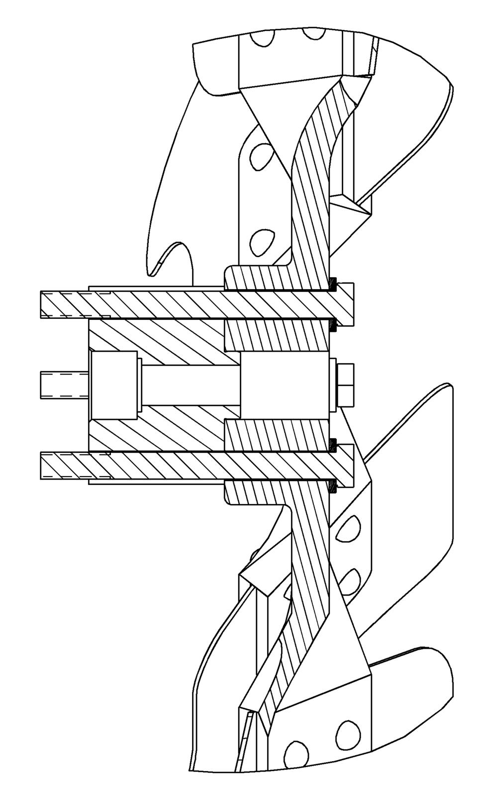
Install the spacer on the engine pulley.
BS07H289-01
STEP 35
Clean the mating surfaces of the fan and spacer, apply anti-seize to the surfaces.
STEP 36
Install the fan and torque mounting bolts to 26 to 33 Nm (19.5 to 24 pound-feet).

BD05H172-01 If equipped, remove the plugs from the hoses and caps from the fittings. Connect the electrical connector for the clutch and the compressor hoses.
STEP 38

BD07F138-01 Connect the electrical connector to the engine controller.
STEP 39

BD07F097-01 Connect a vacuum pump to the fuel tank, turn on the pump. Remove the plugs from the lines and caps the fittings, connect the fuel lines. Turn the vacuum pump off and remove.

BD05H103-01 Connect the battery cable to the starter solenoid and torque to 22.5 to 29.4 Nm (16.5 to 21.6 pound-feet). Push the rubber boot onto the terminal. Connect the ignition switch wire to the bottom of the starter solenoid and torque to 2.6 to 4.6 Nm (23 to 41 pound-in).
STEP 41
Connect the wires to the alternator.

BD07F130-01
STEP 42
Attach lifting equipment to the hood, place the hood in position on the machine.

BD07G158-01 Install the hood front mounting bolts and hand tighten.
STEP 44

BD07F128-01 Install the hood rear mounting bolts and tighten, install the two rubber plugs.
STEP 45
Tighten the front hood mounting bolts, install the two rubber plugs.
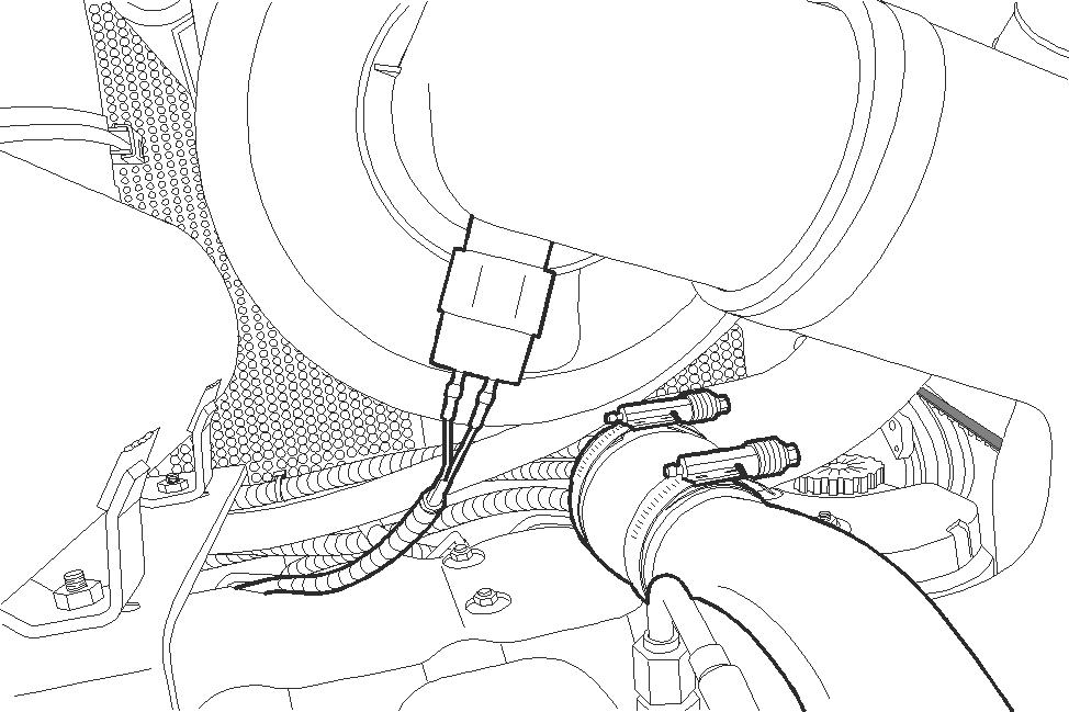
BD07F083-01 Connect the air filter restriction switch, remove and discard tag.
STEP 47
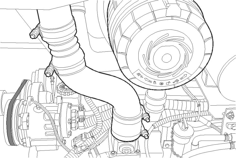
BD07F132-01 Install the after cooler tube. Position clamps and tighten to a torque of 11 to 12 Nm (97 to 106 pound-inch).
STEP 48
BD07F129-01 Install the after cooler tube. Position clamps and tighten to a torque of 11 to 12 Nm (97 to 106 pound-inch).
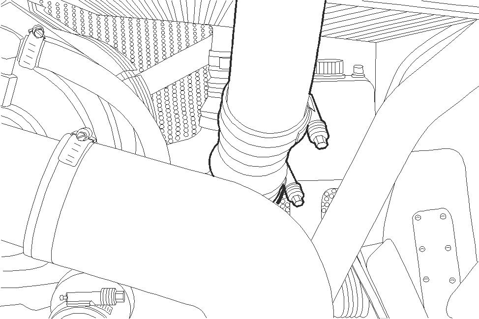
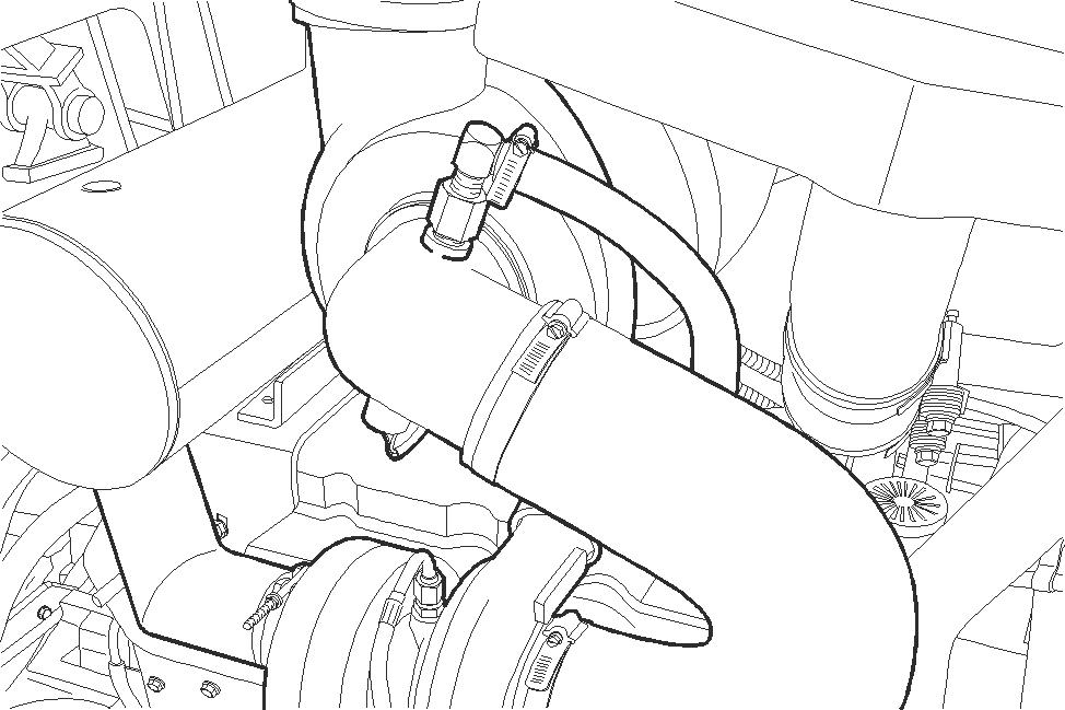
BD07F131-01 Install the air filter hose. Position clamps and tighten to a torque of 3.4 to 4.5 Nm (30 to 40 pound-inch). Connect the crankcase ventilation hose and tighten the clamp.
STEP 50
Install the engine side panels, connect the coolant reservoir hose to the radiator.
STEP 51
Fill the radiator with a mixture of 50% ethylene glycol and 50% water. Install the radiator cap. Fill the coolant reservoir up to the FULL mark on the reservoir.
STEP 52
If equipped with a brush guard, connect suitable lifting equipment to brush guard and move into position. Install the two lower bolts, lock nuts, and washers. Install the two upper bolts and washers. Torque the upper bolts to 570 to 730 Nm (420 to 540 pound-feet).
STEP 53
Check and ensure that the engine has been filled with the correct engine oil, see section 1002.
STEP 54
Start engine and run at low idle. Check for leaks. Check that gauges show the correct indications.
STEP 55
If equipped, see section 9004 and charge the air conditioning system.


