53 minute read
4Operation


4.1General
If you are not yet acquainted with the controls and indicating elements on this machine you should thoroughly read chapter 3 “Indicators and control elements” before starting work. All indicators and control elements are described in detail in this chapter.
4.2Tests before taking into operation
Before the everyday use or before a longer working period the following tests and inspections must be performed.
! Danger
Danger of accident!
Please observe strictly the safety regulations in chapter 2 of this instruction manual!
l Park the machine on ground as level as possible.
Check: l fuel tank and fuel lines for leaks l screw joints for tight fit l function of steering l function of emergency stop l machine for cleanliness, damage l presence of the appropriate operating and maintenance instructions l proper maintenance of the machine

i Note
For a description of the following tasks refer to the chapter "maintenance every 10 operating hours".
l Engine oil level, top up if necessary l Fuel level, top up if necessary. l Coolant level, top up if necessary l Hydraulic oil level, top up if necessary.
Operation
4.3Electronic immobilizer *
Before starting the engine the anti-theft protection must be disarmed by entering a code.
4.4Starting the engine
! Danger
Danger of accident!
Start the engine only from the operator’s seat.
! Caution
In this chapter it is assumed that the operator is fully acquainted with the function of the different control elements on the machine.
i Note
With the electronic immobilizer armed, the light emitting diode (a) (Fig. 44) flashes slowly.
l Slowly enter the six-digit user code.
i Note
When entering the code, the light emitting diode (6) lights up with every digit.
l Press the diamond button.
l The electronic immobilizer is now disarmed and the engine can be started within the next 15 minutes.
l Fasten your seat belt (Fig. 45).
l Check, whether the travel lever (Fig. 46) is engaged to the right in brake position.
*Optional equipment l
Operation
All control and warning lights (Fig. 50) in the instrument cluster light up for a moment.
The engine oil pressure warning light (d) flashes, the charge control light (f) and the parking brake warning light (k) stay on.
Under cold ambient temperatures the preheating control lamp (b) will also light up. Do not start before the preheating control lamp (b) has gone out.
! Caution
Run the starting process for maximum 20 seconds without interruption and pause for a minute between starting attempts.
If the engine has not started after two attempts perform trouble shooting.
i Note
The starter switch is designed with a re-start lock. For a new starting attempt the ignition key must first be turned back to position "0".
l Turn the ignition key (Fig. 51) through position "II" to position "III", the starter will crank the engine.
l As soon as the engine ignites return the ignition key to position "I".
The engine oil pressure warning light and the charge control light go out. The parking brake warning light stays on.
! Caution
Run the engine warm for a short while before starting work. Do not rev up a cold engine to high idle speed/full load speed.
4.5Starting with jump wires
! Caution
A wrong connection will cause severe damage in the electric system.
l Bridge the machine only with a 12 Volt auxiliary battery.
l When jump starting with an external battery connect both plus poles first.
l Then connect the ground cable first to the minus pole of the current supplying auxiliary battery and then to engine or chassis ground, as far away from the battery as possible (Fig. 52).
l Start as described under 'Starting the engine'.
l Once the engine is running switch on a powerful consumer (working light, etc.).
! Caution
If no powerful consumer is switched on voltage peaks may occur when separating the connecting cables between the batteries, which could damage electrical components.
l After starting disconnect the negative poles (ground cable) first and the positive poles after.
l Switch off the consumer.
Operation
4.6Driving the machine
! Danger
Danger of accident!
Wet and loose soils considerably reduce the ground adhesion of the machine on inclinations and slopes.
Soil conditions and weather influences impair the gradability of the machine.
Do not drive up and down inclinations exceeding the maximum gradability of the machine (see technical data).
Do not drive without wearing your seat belt. Always give way to loaded transport vehicles! Before starting to drive make sure that the drive range is absolutely safe.
! Caution
Always keep the cabin door closed while driving with the machine. With the door opened and the machine fully articulated extreme oscillations of the machine may damage the door.
i Note
The machine is equipped with a seat contact switch * (safety feature).
If the driver gets up from his seat while driving, the signal horn is activated and the machine is slowed down to standstill after four seconds. When the driver sits down again t he machine will continue the travel.
Before resuming operation sit down on the seat, engage the travel lever in "0"-position (brake position), then operate the travel lever again to the desired travel direction.
*Only with option SN1 l Shift the travel lever (Fig. 56) out of braking position to the left to disengage. l Move the travel lever slowly to forward or reverse. l Return the travel lever to position "0". The machine decelerates to standstill.
The machine drives forward or backward with a speed that corresponds with the actuation of the travel lever.
! Danger
Danger of accident!
When stopping on inclinations and slopes pull the travel lever to the right and lock it in braking position.
Important notes on travel operation
! Caution
When changing the travel direction hold the travel lever for a moment in "0"-position, until the machine has stopped, before actuating to the new travel direction.
Do not operate jerkily! Control the travel speed with the travel lever.
When driving up and down inclinations move the travel lever slowly back towards neutral to brake the machine.
If the engine speed drops under load when driving on steep gradients, take the travel lever slightly back towards neutral.
4.7Stopping the machine, operating the parking brake
l Return the travel lever (Fig. 57) slowly to "neutral"-position and engage it to the right in braking position.
The machine is automatically braked by the hydrostatic drive and the parking brake is applied.
i Note
The parking brake also closes automatically when shutting the engine down.
Operation
4.8Shutting down the engine
! Caution l Return the travel lever (Fig. 59) slowly to "neutral"-position and engage it to the right in braking position. l Turn the momentary contact switch for engine speed (Fig. 61) anti-clockwise to position "MIN" (idle speed).
Straighten the articulated joint to provide easier access to the machine.
The machine is automatically braked by the hydrostatic drive and the parking brake is applied.
! Caution
Do not shut down the engine all of a sudden from full load speed, but let it idle for about 2 minutes.
i Note
The parking brake also closes automatically when shutting the engine down.
l Turn the starter switch (Fig. 62) to position "0" or "P" and pull the ignition key out.
i Note
The parking brake closes automatically when shutting the engine down.
! Danger
Danger of accident!
Secure the machine against unauthorized use, pull the ignition key out, lock the cabin door.
Operation
4.9Switching the vibration on and off
! Danger
Risk of damage!
When compacting with vibration you must check the effect of nearby buildings and underground supply lines (gas, water, sewage, electric power), if necessary stop compaction with vibration.
! Caution
Danger of bearing damage!
Do not activate the vibration on hard (frozen, concrete) ground.
Pre-selecting the vibration
l Turn the rotary travel speed range switch (Fig. 63) to position "turtle".
l Preselect the desired amplitude with the rotary switch for vibration amplitude preselection (Fig. 64).
Switching the vibration on
! Caution l Turn the rotary momentary contact switch for engine speed (Fig. 65) clockwise to "MAX".
Switch the vibration on only at max. engine speed.
Operation
4.10What to do in events of emergency
Actuating the emergency stop switch
! Danger l Actuate the vibration push button (Fig. 66) in the travel lever while driving.
Danger of accident!
In events of emergency and in case of danger actuate the emergency stop switch immediately.
Switching the vibration off l Press the vibration push button (Fig. 66) again.
Start travel operation of the machine only after the danger that caused the actuation of the emergency stop switch has been eliminated.
! Caution
Do not use as service brake. The deceleration is extremely high. In case of frequent use the wear on the multi-discs brakes will be very high.
l After the end of work turn the vibration amplitude preselecting switch (Fig. 67) back to position "0".
l Press the button of the emergency stop switch (Fig. 68) completely down, it automatically locks in fully pressed position.
i Note
Shuts the engine down and closes the brake.
l Turn the button clockwise to unlock the emergency stop switch.
l Start the engine again, see chapter "Starting the engine".
4.11Adjusting the steering wheel *
l Adjustment of steering wheel in height, pull lever (Fig. 70) up and move the steering wheel to the desired height.
l Adjustment of steering wheel inclination, press lever down and adjust the inclination of the steering wheel.
! Danger
Danger of accident!
After the adjustment make sure that the steering wheel adjustment is securely locked in place.
*Optional equipment
Operation
4.12Adjusting the seat
4.13Operating the heating/air conditioning system *
! Danger i Note l To adjust the seat in longitudinal direction disengage lever e (Fig. 71) upwards and push the seat forward or back. l To adjust the weight turn lever (d) and read the weight in sight glass (c). l To adjust the inclination of the backrest operate lever (a) and tilt the backrest forward or back. l To swivel the seat pull lever (b) up and turn the seat to the desired direction.
Danger of suffocation!
Always keep the air inlet slots on the cabin free of snow, foliage and similar!
The heating power depends on the coolant temperature.
The air conditioning system only works when the engine is running and the fan is switched on.
Operation of the air conditioning system increases the fuel consumption.
Heating the interior
l Close all windows completely.
l To adjust the height of the seat lift the seat up (Fig. 72) until it engages at the desired level. When lifting the seat completely it will sink down to lowest position.
l Turn the air nozzles a (Fig. 73) to direct the air flow down into the footwell.
l In case of cold or damp weather direct the air flow towards the windscreen and door screens.
l Switch on the fan with the rotary switch (c).
l Regulate the temperature with the rotary switch (b).
*Optional equipment
Operation
Cooling the interior
l Close all windows completely.
l Direct the air flow towards the body/face (a).
l Switch on the fan (c).
l If necessary switch off the heating (b).
l Switch on the air conditioning system with rotary switch (d) and regulate the temperature.
Reducing the humidity
l In case of damp weather direct the air flow towards the windscreen and door screens.
l Switch on the fan with the rotary switch (c).
l Regulate the temperature to "Max" with the rotary switch (b).
l Switch the air conditioning (d) on.
4.14Operating the hood
! Danger
Danger of accident!
If the hood needs to be opened further for maintenance or repair work, support it safely.
Bottom position
Fig. 74 l Unlock the lock (Fig. 74). l To open the hood press in the button and turn the handle. l Pull the support out of the bracket and support the hood (Fig. 75).
Top position l Push the hood to top position.
Operation
4.15BVC/BTM05 settings before start-up
Changing the units system
i Note
The Asphalt Manager control unit can be used to change from metric units (km/h, °C) to imperial units (mph, °F) in both the display and the printout * i Note
The control unit shows the start screen.
*Optional equipment
i Note
The menu appears on the screen.
l Press key "F4" (Fig. 79).
i Note
The screen page to select the unit system appears on the screen.
l After the desired change press key "F14" (Fig. 81). The "Save" symbol on the screen lights up green for a moment as confirmation.
i Note
After releasing key "F14" the system returns automatically to the start screen and restarts.
l Press key "F5" (Fig. 80) and choose the units system.
Imperial 0= metric units
Imperial 1= imperial units l Switch the ignition off and on again (Fig. 82).
i Note
Both Asphalt Manager control unit and printer have been set to the new units system.
Setting the printer language *
i Note
With a printer* connected the language in the printout can be changed via the Asphalt Manager control unit.
*Optional equipment l Turn the ignition key to position "I" (Fig. 83).
i Note
The control unit shows the start screen.
l Press key "F6" (Fig. 85).
i Note
The printer language screen page appears.
l Press key ’’?“ (menu) (Fig. 84).
i Note
The menu appears on the screen.
l Use keys "F11" or "F12" to choose the desired printer language (Fig. 86).
i Note
The screen shows country flags, which represent the associated language.
4.16Measuring pass with BTM *
General notes
i Note
The soil measuring values (E VIB) recorded during different passes can only be compared if the recording of measuring values took place in operating mode "Manual" with the same amplitude, frequency and travel speed and on exactly the same track.
Measuring values must only be compared for passes performed in the same direction. The following description describes an measuring pass in forward. Measuring passes in reverse must be performed accordingly.
Measuring pass
*Optional equipment
Operation
l Mark the track to be compacted (Fig. 92).
! Caution i Note
Since the transducer unit is mounted on the left hand side of the drum, it is necessary to arrange the tracks so that track 1 is processed first, followed by further tracks offset to the left.
Maximum track length 150 m.
Forward:
Mark 1= Start of track
Mark 2= End of track i Note
The operator may also remember the start and the end of the track by means of distinct points.
Operation
! Caution
Differences in the travel speeds falsify the measuring result!
Fig. 93 l Pre-select working speed (Fig. 93).
Fig. 96 l Switch the vibration on (Fig. 96).
! Caution
Before reaching mark 1 the nominal exciter shaft speed must have been reached and a valid Evib -value should be displayed.
Fig. 94 l Turn the rotary switch (Fig. 94) for engine speed to position "MAX".
Fig. 97 l When mark 1 is reached, press button F5 “START” (Fig. 97).
Control field to the left of F5 lights green. The EVIB- display shows the present value.
Fig. 95 l Shift the travel lever (Fig. 95) fully to position „I“. l When the end of the track, mark 2, is reached, press the button F6 “STOP” (Fig. 98). l Stop the machine.
The machine accelerates up to the preadjusted travel speed.
i Note
The first forward pass is finished. Control field F5 lights green. This means, that the compaction is not yet completed. One or several passes are still required.
4.17Finishing compaction of a track
Fig. 99 l Drive forward and reverse passes on a track until the green control field to the left of F5 (Fig. 99) goes out and the red control field F6 below lights up after pressing the stop button F6. The compaction process on this track is finished.
Criterion for a finished track:
Compared with the previous track the increase of the EVIB-value in the same travel direction was less than 10%. This criterion is also fulfiled if the EVIB decreases.
i Note
Another pass on this track does not make any sense, because an increase in load bearing capacity is hardly possible with this machine.
l If necessary print out the measuring data for this track (see following section).
l Repeat the complete compaction process on the next track (Fig. 100) to record measuring values.
4.18Printing measuring data after completing compaction *
i Note
Measuring data can be printed after completion of any pass.
Always check the paper provision before starting work.
Change the paper roll if a red stripe appears on the paper.
l At the end of the measurement press push button F7 "PRINT" (Fig. 101).
short actuation= Line diagram long actuation ≥5 sec.= Bar chart
Control field F7 goes out and the measuring value printer starts to print out measuring data.
i Note
After the printing process has finished any amount of diagrams can be printed out by pressing the same button F7 (PRINT).
*only BTM prof
Operation
4.19Changing the paper roll in the measuring value printer *
i Note
Use a new paper roll if a red stripe appears on the paper.
l If no further printouts of this track are needed, press the button F8 “DELETE” (Fig. 102) when the red control lamp F6 “FINISHED” lights up. The red control field F6 “FINISHED” goes out and the green control field F5 “CONTINUE” lights up. BTM plus/prof is ready to compact the next track.
Operation
4.20Changing the printer ribbon in the measuring value printer *
i Note l Insert a new paper roll (Fig. 105). l Feed the paper into the guide (1) on the printer. l Actuate the toggle switch (2) in direction of arrow, until the paper comes out of the printer. l Reassemble the cover. l Unscrew the star handles (Fig. 106) and remove the cover. l Lift the tongue at point 1 (Fig. 107) and take the printer ribbon (2) out of the printer. l Insert the new printer ribbon into the printer, then press in the tongue (1) on the right. l Tension the printer ribbon by turning the rotary button (3) in direction of arrow. l Reassemble the cover.
In case of faint or poorly legible diagrams the printer ribbon needs to be replaced.
*only BTM prof
Operation
4.21Towing in case of an engine failure
! Danger l Secure the machine with wheel chocks against unintentional rolling. l Slacken the middle hexagon on both valves (Fig. 109) for approx. 2 to 3 turns.
Secure the machine with wheel chocks against unintentional rolling.
Danger of accident!
When using towing ropes tow the machine only uphill.
When towing downhill you must use a rigid towing device.
The machine cannot be steered.
! Caution l Attach chains (Fig. 108) or towing ropes to the lifting hooks.
Do not turn the valves out completely.
! Caution l Open the tailgate. l To release the brake turn counter nuts 1 (Fig. 110) approx. 8 mm back. l Turn the brake releasing screws (2) completely in against the stop.
Towing speed 1 km/h, max. towing distance 500 m.
! Caution l Turn the screws in alternately for turn at a time. l Repeat this measure on the opposite wheel side. l Unscrew * plug 1 (Fig. 111) to release the brake in the drum drive motor. l Place clamping disc (4) across the brake housing (2) and turn the screw (5) into the tapped bore (3), until it bottoms. l Turn the nut (6) down and tighten it for approx. one turn. The drum must rotate freely.
From this stop turn the screw in for maximum another turn to release the brake!
Turn the screws in evenly on both sides.
After towing
! Caution
Before detaching the tow bar block the machine with chocks to prevent unintended rolling.
l Turn the high pressure relief valve cartridges tightly back in.
l Turn all brake releasing screws of the axle evenly back out, until they are light moving again.
l Turn the brake releasing screws (Fig. 112) back in again, until they abut against the brake piston.
*only with option SN1 l Unscrew the brake releasing screws (Fig. 113) for two turns and tighten the counter nuts. l Repeat this adjustment procedure on the opposite wheel side. l Unscrew the brake releasing screw from the brake* in the drum drive motor, screw the plug back in and tighten it.
Operation
4.22Loading/transport
! Danger
Danger of accident! Life hazard!
Use only stable loading ramps of sufficient load bearing capacity. The ramp inclination must be less than the gradability of the machine.
Make sure that persons are not endangered by the machine tipping or sliding off. During demonstration and when loading the machine do not remain in the danger zone of the machine.
Always use shackles on the lifting points for loading or tying the machine down. Check all lifting and lashing points for damage before lifting or lashing down the machine. Do not use a damaged or in any other way impaired lifting and lashing eyes.
Lift the machine only with suitable lifting gear. Use only safe lifting gear of sufficient load bearing capacity Minimum lifting capacity of lifting gear: see operating weight in chapter "Technical Data".
The machine must not swing about when being lifted.
Do not step or stand under suspended loads. Lash the machine down, so that it is secured against rolling, sliding and turning over. After transport release the articulation lock again and store it in the receptacle.
Operation
l Lash the machine on the transport vehicle (Fig. 116), use the four lashing eyes on front and rear frame for this purpose.
l Support the front frame to avoid overstressing of the rubber buffers.
Loading by crane
! Danger
Life hazard!
Do not step or stand under suspended loads.
Position of centre of gravity (Fig. 118):
MachineL [mm]H [mm]
BW 211 – 214 -41150 ± 240860 ± 60 i Note
The tolerances account for all possible options, such as cabin, additional weight etc.
After transport
! Danger l For lifting use the four lifting eyes (Fig. 117) and appropriate lifting gear. l After the transport loosen the articulation lock (Fig. 119) again, fix it in its receptacle and lock it with the spring plug.
Danger of accident!
The machine cannot be steered if the articulation lock is applied.
5.1General notes on maintenance
When performing maintenance work always comply with the appropriate safety regulations.
Thorough maintenance of the machine guarantees far longer safe functioning of the machine and prolongs the lifetime of important components. The effort needed for this work is only little compared with the problems that may arise when not observing this rule.
The terms right/left correspond with travel direction forward.
l Support the engine hood for all maintenance and repair work.
l Always clean machine and engine thoroughly before starting maintenance work.
l For maintenance work stand the machine on level ground.
l Perform maintenance work only with the motor switched off.
l Relieve hydraulic pressures before working on hydraulic lines.
l Before working on electric parts of the machine disconnect the battery and cover it with insulation material.
l When working in the area of the articulated joint attach the articulation lock (transport lock).
Environment
During maintenance work catch all oils and fuels and do not let them seep into the ground or into the sewage system. Dispose of oils and fuels environmentally.
Keep used filters in a separate waste container and dispose of environmentally.
Catch biodegradable oils separately.
Notes on the fuel system
The lifetime of the diesel engine depends to a great extent on the cleanliness of the fuel.
l Keep fuel free of contaminants and water, since this will damage the injection elements of the engine.
l Drums with inside zinc lining are not suitable to store fuel.
l When choosing the storage place for fuel make sure that spilled fuel will not harm the environment.
l Do not let the hose stir up the slurry at the bottom of the drum.
l The fuel drum must rest for a longer period of time before drawing off fuel.
l The rest in the drum is not suitable for the engine and should only be used for cleaning purposes.
Notes on the performance of the engine
On diesel engines both combustion air and fuel injection quantities are thoroughly adapted to each other and determine power, temperature level and exhaust gas quality of the engine.
If your engine has to work permanently in "thin air" (at higher altitudes) and under full load, you should consult the customer service of BOMAG or the customer service of the engine manufacturer.
Notes on the cooling system
Prepare and check coolant with highest care, since otherwise the engine may be damaged by corrosion, cavitation and freezing.
Coolant is prepared by adding an ethylene-glycol based anti-freeze agent with corrosion inhibiting properties to the cooling water.
Mixing with cooling system protection agent is necessary in all climatic zones. It prevents corrosion, lowers the freezing point and raises the boiling point of the coolant.
Notes on the hydraulic system
During maintenance work on the hydraulic system cleanliness is of major importance. Make sure that no dirt or other contaminating substances can enter into the system. Small particles can produce flutes in valves, cause pumps to seize, clog nozzles and pilot bores, thereby making expensive repairs inevitable.
l If, during the daily inspection of the oil level the hydraulic oil level is found to have dropped, check all lines, hoses and components for leaks.
l Seal external leaks immediately. If necessary inform the responsible customer service.
l Do not store drums with hydraulic oil outdoors, or at least under a cover. Water can be drawn in through the bunghole when the weather changes.
l We recommend to use the BOMAG filling and filtering unit with fine filter to fill the system. This ensures finest filtration of the hydraulic oil, prolongs the lifetime of the hydraulic oil filter and protects the hydraulic system.
l Clean fittings, filler covers and the area around such parts before disassembly to avoid entering of dirt.
l Do not leave the tank opening unnecessarily open, but cover it so that nothing can fall in.
Maintenance
5.2Fuels and lubricants
Engine oil Quality
For use in DEUTZ engines the lubrication oils are classified in DEUTZ Lubrication Oil Quality Classes (DQC).
Approved engine oils
DeutzACEA *
DQC II-05 or DQC II-10 E3-96, E5-02, E7-08, E4-07, E6-04, E9-08
DQC III-05 or DQC II-10
DQC IV-05 or DQC II-10
API **
CG-4, CH-4, CI-4, CI-4 Plus, CJ-4
DHD-1
*Association des Constructeurs European d’Automobiles
**American Petroleum Institute
The list of approved lubrication oils is also available in the Internet under the following address: www.deutz.com de>>SERVICE >> Betriebsstoffe und Additive >> DeutzQualityClass >> DQC-Freigabeliste en>>SERVICE >> Operating Liquids and Additives >> DeutzQualityClass >> DQC Release List l Use winter grade engine oil for winter operation!
Consult your local service station if in doubt.
Oil viscosity
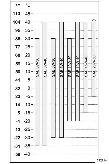
Since lubrication oil changes its viscosity with the temperature, the ambient temperature at the operating location of the engine is of utmost importance when choosing the viscosity class (SAEclass) .
Too high viscosity can cause starting difficulties, too low ´viscosity can jeopardize the lubrication effect and result in a high lubrication oil consumption.
DQC II, DQC III, DQC IV: 500 operating hours
! Caution
When using fuels with a sulphur content of more than 0.5% to 1% or under permanent ambient temperatures below -10°C (14°F) and when using biodegradable diesel fuel the oil change intervals must be halved.
Fuels
You should only use commercially available brand diesel fuel with a sulphur content of less than 0.5% and ensure strict cleanliness when filling in. A higher sulphur content has a negative effect on the oil change intervals.
The fuel level should always be topped up in due time so that the fuel tank is never run dry, as otherwise filter and injection lines need to be bled.
Quality
The following fuel specifications are permitted: l EN 590 l DIN 51628 l ASTM D975 Grade-No. 1-D and 2-D. l JIS K 2204 Grade Fuel 1 and Grade Fuel 2 with lubrication properties acc. to EN 590
Winter fuel
Optimal operating conditions can be achieved by using the oil viscosity chart (Fig. 120) as a reference.
At ambient temperatures below -40°C (-58 °F) the lubrication oil must be pre-heated (e.g. by parking the machine indoors).
The viscosity is classified acc. to SAE. Multi-purpose oils should generally be used.
Oil change intervals
The longest permissible time a lubrication oil should remain in an engine is 1 year. If the following oil change intervals are not reached over a period of 1 year, the oil change should be performed at least once per year, irrespective of the operating hours reached.
For winter operation use only winter diesel fuel, to avoid clogging because of paraffin separation. Diesel fuels suitable for temperatures down to -44 °C (-47 °F) are available for Arctic climates. At very low temperatures disturbing paraffin separation can also be expected when using winter diesel fuel.
The admixture of petroleum and the addition of "flow enhancing additives" (fuel additives) is not permitted.
Coolant
For fluid cooled engines the cooling fluid must be prepared by admixing a cooling system protection agent to the fresh water and should be checked within the specified maintenance intervals. This prevents damage caused by corrosion, cavitation, freezing and overheating.
Fresh water quality
The correct quality of water is highly important when preparing coolant. Clear and clean water within the boundaries of the following analysis values should generally be used.
Fresh water analysis values
pH-value at 20 °C (68 °F)6.5 - 8.5
Chloride ion content (mg/l) (ppm)max. 100
! Caution
Another analysis must be made after the fresh water has been prepared.
Cooling system protection agent
As a protection against frost, corrosion and boiling point anti-freeze agents must be used under any climatic conditions.
Coolant for fluid cooled engines is prepared by adding an ethylene-glycol based anti-freeze agent with corrosion inhibiting properties to the cooling water.
We therefore highly recommend our BOMAG cooling system protection agent.
3.56
Sulphate ion content (mg/l) (ppm) max. 100 Water hardness (ion content of calcium and magnesium ) (mmol/l)]
Conversion to other units:
- German degree (°dH)]max. 20
- English degree (°eH)]max. 25
- French degree (°fH)]max. 36.5 corresponds with the content of CaCO 3 (mg/l) (ppm) max. 356 l pH-value too low l Water hardness too high: Mix with soft, distilled or fully demineralized water l Chlorides and/or sulphates too high: Mix with distilled or fully demineralized water l Total hardness or carbonate hardness too low: Mix with hardened water (harder water is in most cases available in the form of drinking water).
Information concerning the water quality can be obtained from the waterworks.
If the fresh water analysis values are unknown, these must be determined with the help of a water analysis.
If the values of the analysis deviate, the water must be treated accordingly.
Adding of caustic lye of soda or caustic potash solution.
If our cooling system protection agent is not available for any important reasons, you may, in exceptional cases, use products that have been approved by the engine manufacturer.
The list of approved cooling system protection agents is also available in the Internet under the following address: www.deutz.com de>>SERVICE >> Betriebsstoffe und Additive >> Kühlsystemschutz >> Kühlsystemschutz Technisches Rundschreiben en>>SERVICE >> Operating Liquids and Additives >> Cooling System Conditioner >> Flyer Cooling System Conditioner Technical Circular
Products of the same product group (see Deutz Technical Circular Cooling System Protection Agents) can be mixed with each other.
The BOMAG cooling system protection agent corresponds with product group A.
! Caution
Do not mix different coolants and additives of any other kind.
Before changing the product you must clean the entire cooling system.
Consult your local service station if in doubt.
To ensure proper corrosion protection you must use the cooling system protection agent all year around, whereby the following concentration must not be fallen short of or exceeded.
Mixing ratio
Cooling system protection agent
Fresh waterCold protection down to min. 35%65%-22 °C (-8 °F)
40%60%-28 °C (-18 °F)
45%55%-35 °C (-31 °F) max. 50%50%-41 °C (-42 °F)
! Caution
A proportion of more than 50% of cooling system protection agent causes a drop in cooling power.
The use of corrosion protection oils as cooling system protection agents is not permitted.
i Note
When working at temperature below -41 °C(-42 °F) you should consult our local service representative.
Environment
Coolant must be disposed of environmentally.
Mineral oil based hydraulic oil
The hydraulic system is operated with hydraulic oil HV 46 (ISO) with a kinematic Viskosität von 46 mm2/s bei 40 °C und 8 mm2/s bei 100 °C betrieben. For topping up or for oil changes use only high-quality hydraulic oil, type HVLP according to DIN 51524, part 3, or hydraulic oils type HV according to ISO 6743/3. The viscosity index (VI) should be at least 150 (observe information of manufacturer).
Bio-degradable hydraulic oil
The hydraulic system can also be operated with a synthetic ester based biodegradable hydraulic oil. The biologically quickly degradable hydraulic oil Panolin HLP Synth.46 meets all demands of a mineral oil based hydraulic oil according to DIN51524.
In hydraulic systems filled with Panolin HLP Synth.46 always use the same oil to top up. When changing from mineral oil based hydraulic oil to an ester based biologically degradable oil, you should consult the lubrication oil service of the oil manufacturer for details.
! Caution
Check the filter more frequently after this change.
Perform regular oil analyses for content of water and mineral oil.
Replace the hydraulic oil filter element every 500 operating hours.
Gear oil
For the gearboxes use only ,ulti-purpose gear oils ISO VG 220 of API-GL5-class with a minimum viscosity of 20 mm2/s at 100°C.
This is a hypoid lubricant of highest quality class for extremely loaded transmissions.
The additives in this oil ensure low wear lubrication under all operating conditions.
Exciter shaft oil
For the exciter unit in the drum use a fully synthetic gear oil SAE 75W-90, API GL5.
Lubrication grease
For lubrication purposes use an EP-high pressure grease, lithium saponified (penetration 2), acc. to DIN 51502 KP 2G.
Maintenance
5.3Table of fuels and lubricants
AssemblyFuel or lubricantQuantity
SummerWinterAttention
Observe the level marks
Motor
- Engine oilACEA: E3-96, E5-02, E7-04, E4-07, E6-04
API: CG-4, CH-4, CI-4, CI-4 Plus, CJ-4
SAE 10W-40 (-15 °C to +40 °C) (BOMAG 009 920 06; 20 l)
SAE 15W-40 (-15 °C to +40 °C)
SAE 5W-40 (-30 °C to +40 °C) approx. 15.5 litres
- Fuel Diesel Winter diesel fuelapprox. 340 litres
- Coolant Mixture of water and anti-freeze agent Specification see "Fuels and lubricants - coolant"
Hydraulic systemHydraulic oil (ISO), HLP 46 (BOMAG 009 930 09; 20 l) or ester based biodegradable hydraulic oil
Vibration bearings
Drive axle
Wheel hubs
SAE 75W-90, API GL-5 (BOMAG 009 925 05; 20 l)
SAE 80W-140, API GL-5 (BOMAG 009 925 07; 20 l)
SAE 80W-140, API GL-5 (BOMAG 009 925 07; 20 l) approx. 16 litres approx. 60 litres approx. 1.0 litres approx. 9.5 litres approx. 1.9 l each
TiresWaterapprox. 295 litres
Calcium chloride (CaC2) or magnesium chloride (MgCl22) approx. 100 kg
Air conditioning systemRefrigerant R134aapprox. 1500 g
5.4Running-in instructions
The following maintenance work must be performed when running in new machines or overhauled engines:
! Caution
Up to approx. 250 operating hours check the engine oil level twice every day.
Depending on the load the engine is subjected to, the oil consumption will drop to the normal level after approx. 100 to 250 operating hours.
After a running-in time of 30 minutes l Retighten the V-belt
After 250 operating hours l Retighten bolted connections on intake and exhaust tubes, oil sump and engine mounts. l Retighten the bolted connections on the machine. l Retighten all wheel fastening screws with the specified tightening torque. l Change engine oil and oil filter l 1. Oil change vibration bearings l Oil change in drive axle l Oil change in wheel hubs
After 500 operating hours l 2. Oil change vibration bearings
5.5Maintenance table
5.35 Check, adjust the valve clearanceIntake valve: 90° +10° Exhaust: 150° +10°
5.36 Change hydraulic oil and breather filter** at least every 2 yearsX
5.37 Change the hydraulic oil filter**at least every 2 yearsX
5.38 Change the coolantat least every 2 yearsX
5.39 Replace ribbed V-belt and idler pulley at least every 2 yearsX
5.40 Replace the injection valvesonly by authorized service personnel
5.41 Replace the crank case ventilation valve at least every 2 yearsX
*oil change after 250 and 500 operating hours, then every 500 operating hours
**Also in case of repair in the hydraulic system.
***Running-in instructions: oil change after 250, 500 and 1000 operating hours, then every 1000 operating hours
****Running-in instructions: oil change after 250 and 1000 operating hours, then every 1000 operating hours
*****Running-in instructions: oil change after 250 and 1000 operating hours, then every 1000 operating hours
Every 10 operating hours
5.6Checking the engine oil level
! Danger
Danger of injury!
Support the engine hood for all maintenance and repair work.
! Caution
The machine must be in horizontal position. If the engine is warm, shut it down and check the oil level after five minutes.
With a cold engine the oil level can be checked immediately.
For quality of oil refer to the "table of fuels and lubricants".
5.7Checking the fuel level
! Caution
Do not drive the fuel tank dry, as otherwise the fuel system needs to be bled.
Fig. 121 l Pull the dipstick (Fig. 121) out, wipe it off with a lint-free, clean cloth and reinsert it until it bottoms. l Pull the dipstick back out. l The oil level must always be between the "MIN"- and "MAX"-marks. If the oil level is too low, top up oil to the "MAX" mark immediately.
Fig. 122 l Check the fuel level on fuel gauge (m) (Fig. 122) in the instrument cluster.
Refuelling
! Danger
Fire hazard!
When working on the fuel system do not use open fire, do not smoke, do not spill any fuel. Do not refuel in closed rooms. Shut down the engine.
! Danger
Health hazard!
Do not inhale any fuel fumes.
! Caution
Monitor the entire refuelling process. For quality and quantity of fuel refer to the "table of fuels and lubricants".
Environment
Catch running out fuel, do not let it seep into the ground.
Every 10 operating hours
5.8Check the coolant level
! Danger
Danger of scalding!
Fill up coolant only when the engine is cold.
! Caution
If, during the daily inspection the coolant level is found to have dropped, check all lines, hoses and engine for leaks.
Fig. 123 l Shut down the engine. l Clean the area around the filler opening. l Open the fuel tank cover (Fig. 123).
! Caution l Top up with fuel (diesel or winter diesel). l Screw the fuel tank cover back on.
Contaminated fuel can cause malfunction or even damage of the engine.
If necessary, fill in fuel through a funnel with screen.
Do not use radiator sealant to seal leaks. For quality and quantity of coolant refer to the "table of fuels and lubricants".
Fig. 124 l Check the coolant level (Fig. 124). l To top up unscrew the filler cap and fill in coolant up to the MAX-mark.
Every 10 operating hours
5.9Check the hydraulic oil level
! Caution
In hydraulic systems filled with Panolin HLP Synth. 46 always use the same oil to top up. With other ester based oils consult the lubrication oil service of the respective oil manufacturer.
l Check the hydraulic oil level in the inspection glass (Fig. 125).
Normal level approx. 3 cm below the top edge of the inspection glass.
Minimum level
Middle of inspection glass.
! Caution
If, during the daily inspection of the oil level the hydraulic oil level is found to have dropped, check all lines, hoses and components for leaks.
l If necessary fill in hydraulic oil through the filler neck.
For quality and quantity of oil refer to the table of fuels and lubricants.
Every 250 operating hours
5.10Check the tire pressure
! Caution i Note
Because of the water filling in the tires, you should always check the tire pressure with the tire valve in top position!
Always close the valves with their dust caps.
Adaptation to operating conditions:
The tire pressure can be adapted to the operating conditions within the specified limits.
A reduced tire pressure improves the traction especially on sandy soils. Higher tires pressures improve the driving stability of the machine.
The total height of the machine can also be influenced by changing the tire pressure.
5.11Clean the cooling fins on engine and hydraulic oil
cooler
! Danger
Danger of injury!
Perform cleaning work only after the engine has cooled down and with the engine stopped.
! Caution i Note
Do not damage any cooling fins on the cooler core when cleaning.
Dirt on fan blades and oil cooler reduce the cooling effect. Dirt deposits in these areas are substantially supported by oil and fuel on these surfaces. For this reason you should always seal any oil or fuel leaks in the vicinity of the cooling fan or the oil cooler and clean the cooling surfaces after.
Cleaning with compressed air
l With the tire inflation valve check the air pressure on tire inflation valve 1 (Fig. 126) with a pressure gauge.
Nominal value, see "technical data".
i Note l Screw the valve caps back on again. i Note l Blow the cooler (Fig. 127) out with compressed air.
Ensure equal pressure in all rubber tires!
Start to blow out from the exhaust side.
Every 250 operating hours
Cleaning with cold cleansing agent
! Caution
Protect electrical equipment such as generator, regulator and starter against the direct water jet.
l Spray the engine with a suitable cleansing agent, e.g. cold cleanser, let it soak in for a while and spray it off with a strong water jet.
l Run the engine warm for a while to avoid corrosion.
5.12Check the oil level in the drive axle
l Park the machine on level ground.
l Unscrew the oil level inspection plug (Fig. 128) and check the oil level.
i Note
The second level inspection plug as at the back. After filling in oil wait until the oil has evenly distributed inside the axle.
The oil level must reach the bottom edge of the level bore.
l Top up oil, if necessary.
For quality of oil refer to the table of fuels and lubricants.
l Turn the level inspection plug tightly back in.
Every 250 operating hours
5.13Check the oil level in the wheel hubs
! Caution
Check the oil level in both wheel hubs. For quality of oil refer to the "table of fuels and lubricants".
5.14Check the oil level in the vibration bearings
! Caution
Check only at operating temperature after running the machine approx. 1/2 hour with vibration.
Danger of bearing damage! Make sure that no dirt falls into the exciter housing.
If a loss of oil is found perform trouble shooting, repair the drum if necessary.
For quality of oil refer to the "table of fuels and lubricants".
l Park the machine on level ground.
l Park the machine so that the plug (1) (Fig. 129) is in horizontal position.
l Clean the area around the plug and unscrew the plug.
l Check the oil level. The oil level must reach the bottom edge of the bore, top up oil if necessary.
l Screw the plug back in tightly.
l Move the drum, until oil level inspection plug (1) (Fig. 130) on the left hand side of the drum is in bottom position.
l Thoroughly clean the area around the level inspection and filler plug.
l Unscrew level inspection plug (1).
Some oil should run out of the inspection bore.
l If necessary unscrew oil filler plug (2) and fill in some oil through the oil filler bore (2), until oil starts to drip out through the inspection bore.
l Screw oil filler (2) and level inspection plug (1) back in tightly.
l Repeat this inspection on the other side.
Every 250 operating hours
5.15Check the parking brake
! Danger l Park the machine on level ground. l Open the engine hood. l Shift the travel lever (Fig. 133) out of braking position to the left to disengage. l Pull the travel lever back first. l Then shift the travel lever forward.
Life hazard!
Before checking the parking brake make sure that there are no persons or obstacles in front or behind the machine.
! Caution
l Pull the plug off the brake solenoid valve(Fig. 131).
l Start the engine.
l Turn the rotary momentary contact switch for engine speed (Fig. 132) clockwise to "MAX".
The machine should not move during this test. However, if the machine moves the parking brake needs to be adjusted or repaired. Adjustments to the parking brake must only be made by authorized service personnel! Only operate the machine after the travel control has been repaired.
l Reconnect the plug to the parking brake solenoid valve (Fig. 131).
l Close the engine hood.
Every 250 operating hours
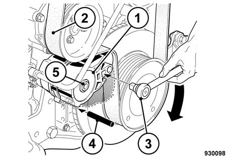
5.16Checking, replacing the refrigerant compressor Vbelt *
! Danger
Danger of injury!
Work on the V-belt must only be performed with the engine shut down.
Check the V-belt l Inspect the entire circumference of the V-belt (Fig. 134) visually for damage and cracks. Replace damaged or cracked V-belts. l Check with thumb pressure whether the V-belt can be depressed more than 10 to 15 mm (0.4 – 0.6 inches) between the V-belt pulleys, retighten if necessary. l Slightly slacken fastening screws 1, 2 and 3 (Fig. 135). l Press the compressor in direction of arrow, until the correct V-belt tension is reached. l Retighten all fastening screws.
Tighten the V-belt.
Changing the V-belt l Slightly slacken the fastening screws 1, 2 and 3. l Press the compressor against the direction of arrow completely against the engine. l Take the old V-belt off. l Fit the new V-belt to the V-belt pulleys. l Tension the V-belt as previously described.
! Caution
Check the V-belt tension after a running time of 30 minutes.
*Optional equipment
5.17Changing engine oil and oil filter
! Danger Danger of scalding!
When draining off hot oil. By hot oil when unscrewing the engine oil filter.
! Caution
Drain the oil only when the engine is warm. For quality and quantity of oil refer to the "table of fuels and lubricants".
Environment l Thoroughly clean the outside of the filter cartridge (Fig. 137). l Unscrew the filter cartridge using an appropriate filter wrench. l Clean the sealing face on the filter carrier from any dirt. l Slightly oil the rubber seal on the new filter cartridge. l Unscrew the drain plug (Fig. 136) and catch running out oil. l Turn the drain plug tightly back in. l Turn the new filter cartridge (Fig. 138) on by hand, until the seal contacts. l Tighten the filter element for another half turn.
Catch running out oil and dispose of environmentally together with the oil filter cartridge.
Fig. 139 l Fill in new engine oil (Fig. 139). l Tighten the oil filler cap properly. l After a short test run check the oil level on the dipstick . The oil level should reach the MAXmark, top up oil if necessary. l Check filter cartridge and drain plug for leaks.
5.18Check, clean the water separator
! Danger
Fire hazard!
When working on the fuel system do not use open fire, do not smoke.
Environment i Note
Any fuel must be caught and disposed of in an environmentally friendly manner.
The service intervals for the water separator depend on the water content in the fuel and can therefore not be determined precisely. After taking the engine into operation you should check the filter bowl initially every day, later as required, for signs of water.
If a too high quantity is drained off, the filter needs to be bled, see section "Replacing the fuel precleaner cartridge".
Fig. 140 l If the "water in fuel" warning light (a) (Fig. 140) lights up when starting or during operation, drain the water from the fuel filter immediately. l Slacken the drain plug (Fig. 141) for a few turns and catch running out fuel / water. l Turn the plug tightly back in. Check for leaks, if necessary use a new seal ring.
i Note
Once the water separator is empty the warning light for water in fuel must go out.
Every 500 operating hours
5.19Draining the sludge from the fuel tank
! Danger
Fire hazard!
When working on the fuel system do not use open fire, do not smoke!
Do not spill any fuel.
Catch running out fuel, do not let it seep into the ground.
Do not inhale any fuel fumes.
Fig. 142 l Unscrew the cap (Fig. 142) and drain off approx. 5 litres of fuel. l Turn the cap tightly back in.
5.20Battery service
! Danger
Danger of cauterisation ! Danger of explosion!
When working on the battery do not use open fire, do not smoke!
The battery contains acid. Do not let acid come in contact with skin or clothes!
Wear protective clothing!
Do not lay any tools on the battery!
For recharging remove the plugs from the battery to avoid the accumulation of highly explosive gases.
Environment
Dispose of the old battery environmentally.
i Note
Maintenance free batteries also need care. Maintenance free only means that the fluid level does not need to be checked. Each battery suffers under self-discharge, which may, in not checked occasionally, even cause damage to the battery as a result of exhaustive discharge.
The following therefore applies for the service life: l Switch off all consumers (e.g. ignition, light, inside light, radio). l Check open-circuit voltage of the battery at regular intervals. At least once per month. l Recharge the battery immediately after an open-circuit voltage of 12.25 V or less is reached. Do not perform quick charging. The open-circuit voltage of the battery occurs approx. 10 hours after the last charging process or one hour after the last discharge. l After each charging process allow the battery to rest for one hour before taking it into service. l For resting periods of more than one month you should always disconnect the battery. Do not forget to perform regular open-circuit voltage measurements.
Reference values: 12.6 V = fully charged; 12.3 V = 50% discharged.
! Caution
Exhausted batteries (batteries with formation of sulphate on the plates) are not covered under warranty!
l Open the engine hood and remove the covering l Remove the battery (Fig. 143) and clean the battery compartment. l Clean the outside of the battery. l Clean battery poles and pole clamps and grease them with pole grease (Vaseline). l Check the fastening of the battery. l On serviceable batteries check the acid level, if necessary top up to the filling mark with distilled water.
5.21Service the air conditioning *
Clean the condenser
! Danger
Danger of accident!
Do not clean with a hot water jet. Heat will cause extreme overpressure, which could cause damage or explosion of the system. Use access steps and grips to mount and dismount the machine.
! Caution
A soiled condenser results in a considerable reduction of air conditioning power.
Under extremely dusty conditions it may be necessary to clean the condenser several times per day.
If, during operation of the air conditioning system, the warning buzzer sounds switch the air conditioning off and clean the condenser. In case of formation of foam have the air conditioning system inspected by the service department.
Checking the refrigerant level l Start the engine. l Turn the rotary switch for the cab ventilator (Fig. 145) to position "1". l Unscrew the condenser fastening screws (Fig. 144) and fold the condenser forward. l Clean the condenser fins on front and back with compressed air or cold water .
*Optional equipment l Choose a cooling temperature with the rotary switch for the air conditioning system (Fig. 146) in the blue section. l Open the air outlet nozzles. l Check, whether the out flowing air is noticeably cooler.
i Note
The adjusted temperature must be below the actual temperature inside the cabin, so that the compressor will be switched on.
i Note
The refrigerant level is correct.
Checking the moisture level of the drying agent
i Note
The refrigerant level is not correct.
l Refrigerant must be filled up, if necessary check the air conditioning system for leaks.
orange= Drying agent o.k.
colour- less= moisture level of drying agent too high. l Inform the service department. Replace drier/ collector unit, check air conditioning system.
! Caution
Have the drier/collector unit replaced by the service department every year before the operating season.
Checking the condition of the drier/collector unit
! Caution
According to the regulation for pressure reservoirs all pressure reservoirs must be repeatedly inspected by a specialist. In this sense repeated inspections are external examinations, normally on pressure reservoirs in operation. In connection with this inspection the drier/collector unit must be visually examined twice every year. During these inspections special attention must be paid to corrosion and mechanical damage. If the reservoir is not in proper condition it must be replaced for safety reasons, as a precaution to protect operators and third parties against any danger arising from the handling and operation of pressure reservoirs.
! Danger
Danger of injury!
In case of mechanical damage or corrosion on this drier/collector unit this unit must be replaced, to avoid bursting and further damage.
Every 500 operating hours
5.22Cleaning the circulation air filter for the heating *
l Check the drier/collector unit (Fig. 150) for mechanical damage or rust.
l Unscrew screws (1) (Fig. 151).
l Pull the filter (2) downwards out.
l Clean the filter, replace if necessary.
l Assemble the filter and tighten the screws.
*Optional equipment
Every 500 operating hours
5.23Changing the bypass filter
! Danger
Danger of scalding!
Danger of scalding by hot oil when unscrewing the oil filter.
! Caution
If the filter has to be changed together with the hydraulic oil, the filter must only be changed after the oil change and after the test run.
Replace the filter element at the latest after one year
Environment l Replace the filter
Dispose of the old filter element environmentally.
*Optional equipment
Every 1000 operating hours
5.24Checking / replacing the ribbed V-belt
! Danger
Danger of injury!
Work on the V-belt must only be performed with the engine shut down.
Checking the wear limit of the ribbed Vbelt
Changing the ribbed V-belt l Check the distance between the tongue of the moveable tensioner arm and the fixed tensioner housing (Fig. 154). l If measurement "a" is smaller than 3 mm, replace the ribbed V-belt. l Release the idler pulley (Fig. 156) in direction of arrow until the ribbed V-belt is free. l Pull the ribbed V-belt first to the smallest pulley. l Install the new ribbed V-belt. l Release the idler pulley against the direction of arrow until the V-belt is tensioned. l Measure the V-belt tension, tighten if necessary.
i Note
Retighten the new fan V-belt after a running time of 20 minutes.
Every 1000 operating hours
5.25Replace the fuel filter cartridge
! Danger
Fire hazard! Health hazard!
When working on the fuel system do not use open fire, do not smoke and do not spill any fuel.
Do not inhale any fuel fumes.
! Caution
Ensure strict cleanliness! Thoroughly clean the area around the fuel filters.
The filter cartridge must never be filled beforehand.
After work on the fuel system bleed the system, perform a test run and check for leaks.
Additional bleeding of the fuel system by a 5 minute test run in idle speed or low load is mandatory.
Environment
Catch running out fuel and dispose of environmentally.
l Slightly oil the rubber seal (Fig. 158) on the new filter cartridge.
l Turn the new filter cartridge on by hand, until the seal contacts.
l Tighten the filter element for another half turn.
l Loosen and unscrew the fuel filter cartridge (Fig. 157) using an appropriate filter wrench.
l Clean the sealing face on the filter carrier from any dirt.
5.26Change the fuel pre-filter cartridge
! Danger
Fire hazard! Health hazard!
When working on the fuel system do not use open fire, do not smoke and do not spill any fuel.
Do not inhale any fuel fumes.
! Caution
Ensure strict cleanliness! Thoroughly clean the area around the fuel filters.
The filter cartridge must never be filled beforehand.
After work on the fuel system bleed the system, perform a test run and check for leaks.
Additional bleeding of the fuel system by a 5 minute test run in idle speed or low load is mandatory.
Environment
Catch running out fuel and dispose of environmentally.
Change the fuel pre-filter cartridge
l (2) Loosen and unscrew the fuel pre-filter cartridge using an appropriate filter wrench.
l (3) Unscrew the water separator from the filter cartridge.
l (4) Apply a thin coat of oil to the rubber seal of the water separator.
l (5) Turn the water separator on by hand, until the seal contacts, then tighten hand-tight.
l (6) Apply a thin coat of oil to the rubber seal of the filter element (5).
l (7) Turn the filter cartridge on by hand, until the seal contacts, then tighten hand-tight.
l Plug the water sensor cable back on.
Bleed the fuel system
i Note l Tighten the cable on the water separator (Fig. 159). l (1) Loosen the bleeding screw and drain off fuel from the bleeding screw. l Slacken the bleeding screw (Fig. 160) on the fuel pre-filter for 2 to 3 turns. l Operate the hand pump manually, until fuel flows out of the slackened bleeding screw without air bubbles. l Then tighten the bleeding screw while pumping. l Check the filter cartridge for leaks
Air in the fuel system causes irregular running of the engine, a drop in engine power, stalls the engine and makes starting impossible.
Therefore bleed the fuel system after changing the fuel pre-filter or working on the fuel system.
Every 1000 operating hours
5.27Check the engine mounts
5.28Change the oil in the vibration bearings
! Danger
Danger of scalding when draining off hot oil!
! Caution
Drain oil only at operating temperature. For this purpose run the machine approx. half an hour with vibration.
For quality and quantity of oil refer to the "table of fuels and lubricants".
Fig. 161 l Tighten fastenings of intake and exhaust manifolds (Fig. 161) on the cylinder heads. l Check sockets and clamps between air filter, exhaust turbocharger and charge air line as well as the lubrication air line for tight fit and leaks. l Retighten the fastening screws for oil sump and engine mounts.
! Caution
Danger of bearing damage!
Make sure that no dirt falls into the exciter housing.
Overfilling causes overheating and destruction of the vibration bearings!
Environment l Park the machine on level ground. l Move the drum, until the drain plug 1 (Fig. 162) is in bottom position. l Unscrew the drain plug, let the oil run out and catch it. l Turn the oil drain plug back in tightly after all oil has run out. l Unscrew oil level inspection plug (1) (Fig. 163) on the drum and fill in oil through the filler opening (2), until it starts to drip out from the level inspection bore. l Screw oil filler (2) and level inspection plug (1) back in tightly. l Repeat the oil change on the opposite side. l Check the oil level once again at operating temperature (after running the machine for about half an hour with vibration).
Catch running out oil and dispose of environmentally.
Every 1000 operating hours
5.29Change the oil in thedrive axle
! Danger
Danger of scalding when draining off hot oil!
! Caution
Drain oil only at operating temperature.
For quality and quantity of oil refer to the "table of fuels and lubricants".
Environment i Note l Park the machine on level ground. l Clean and unscrew all level inspection and drain plugs (Fig. 164). l Drain and catch all oil. l Clean the drain plug and turn it back in with a new seal ring.
Catch running out oil and dispose of environmentally.
On other axle versions drain and filler plugs are of slightly different design. Perform the oil change accordingly.
Every 1000 operating hours
5.30Changing the oil in the wheel hubes
! Danger
Danger of scalding when draining off hot gear oil!
! Caution l Fill in oil through the oil level inspection bores (Fig. 165), until it has reached the bottom edge of the bore.
i Note
The second level inspection plug as at the back. After filling in oil wait until the oil has evenly distributed inside the axle.
l Retighten the filler and level inspection plug.
Drain oil only at operating temperature. Change the oil on both sides of the axle. For quality and quantity of oil refer to the "table of fuels and lubricants".
Environment l Move the drive wheel, until the plug (Fig. 166) is in bottom position. l Clean and unscrew the plug. l Drain and catch all oil. l Move the drive wheel, until the plug (Fig. 167) is in horizontal position on the housing. l Fill in oil, until it reaches the bottom edge of the bore . l Turn the plug tightly back in. l Change the oil also on the opposite side.
Catch running out oil and dispose of environmentally.
Every 1000 operating hours
5.31Retighten the fastening of the axle on the frame
5.32Tightening the wheel nuts
5.33Check the ROPS
i Note
On machines with cabin the ROPS (roll over protection structure) is an integral part of the cabin. Please observe also the corresponding section in the safety regulations in this manual.
l Inspect the cabin, especially the ROPS (Fig. 170), for cracks, corrosion, damage and missing fastening parts.
i Note
Unusual movements and noises (vibrations) during operation are signs for damage or loosened fastening elements.
l Check the fastening screws for the cabin (ROPS) to the operator’s stand for tight fit.
l Check the rubber buffers of the operator’s platform suspension for condition and tight fit.
l Check the condition and fastening of the seat belts.
5.34Check the travel control
l Move the travel lever (Fig. 171) forward, backwards and to braking position. Thereby check for function, light movement, clearance and damage.
l In case of malfunction perform trouble shooting and replace the corresponding parts.
! Caution
Only operate the machine after the travel control has been repaired.
5.35Adjust the valve clearance
! Caution
We recommend to have this work carried out by trained personnel or our after sales service. Before checking the valve clearance let the engine cool down for at least 30 minutes. The engine oil temperature must be less than 80 °C.
l Remove the valve covers.
l Turn the crankshaft with the cranking device until the valves are overlapping.
i Note
Firing order 1-3-4-2 l Attach the rotation angle disc (3) and the spanner socket (4) to the valve clearance adjustment screw (2). l Fix the magnet (5) of the rotation angle disc. l Turn the rotation angle disc clockwise against the stop (rocker arm no clearance) and set the scale to zero. l Turn the rotation angle disc counter-clockwise, until the specified angle is reached.
Overlapping of valves: Exhaust valve not yet closed, intake valve starts to open.
Intake valve= 90° +10°
Exhaust valve = 150° +10° l Hold the rotation angle disc tight, so that it does not turn, and tighten counter nut (1).
Tightening torque: 20 Nm l Repeat this adjustment procedure an all other cylinders, after cranking the crankshaft accordingly. l Install the cylinder head cover with a new gasket.
Tightening torque: 13 Nm l After a short test run check the engine for leaks.
Every 2000 operating hours
5.36Changing hydraulic oil and breather filter
i Note
See also the notes on the hydraulic system in the chapter "General notes on maintenance".
! Danger
Danger of scalding!
When draining off hot hydraulic oil!
! Caution
The hydraulic oil must also be changed after major repairs in the hydraulic system.
Perform the oil change when the hydraulic oil is warm.
Replace the hydraulic oil filter elements with every hydraulic oil change.
Change the filter only after the hydraulic oil change and after the test run.
Clean the area round hydraulic oil tank, filler opening and breather filter.
Do not start the engine after draining the hydraulic oil.
Do not use any detergents to clean the system. Use only lint-free cleaning cloths.
For quality and quantity of oil refer to the "table of fuels and lubricants".
When changing from mineral oil based hydraulic oil to an ester based biologically degradable oil, you should consult the lubrication oil service of the oil manufacturer for details.
Environment
Catch running out hydraulic oil and dispose of environmentally.
l Unscrew the plug (Fig. 173) and drain off all hydraulic oil.
l Check the seal ring, replace if necessary and turn the plug tightly back in.
l Remove the fille r cap (Fig. 174).
l Fill in new hydraulic oil through the screen.
i Note
We recommend to use the BOMAG filling and filtering unit with fine filter to fill the system. This ensures finest filtration of the hydraulic oil, prolongs the lifetime of the hydraulic oil filter and protects the hydraulic system.
l Check the oil level in the inspection glass.
Nominal value: approx. 3 cm below the upper edge of the inspection glass
i Note
The breather filter for the hydraulic oil tank is integrated in the filler cap. You should therefore replace the complete filler cap.
l Close the tank with a new cover.
5.37Changing the hydraulic oil filter
! Danger
Danger of scalding!
There is a danger of scalding by hot oil when unscrewing the filter.
! Caution
If the filter has to be changed together with the hydraulic oil, the filter should in any case be changed after the oil change and the test run. Do not use the oil in the filter bowl.
Environment
Catch running out oil, dispose of oil and filter element environmentally.
i Note
The filter element must be changed with every hydraulic oil change and after major repairs in the hydraulic system.
Fig. 175 l Unscrew the cap nut 4 (Fig. 175) and take the filter bowl (5) with the filter element (3) off. l Examine the sealing face on the filter element thoroughly for any visible dirt.
! Caution
Visible impurities may be an early indicator for a failure of system components and predict the
Every 2000 operating hours
possible malfunction of important parts. In such a case you should perform trouble shooting and replace or repair the defective components. Nonobservance may lead to total damage of the hydraulic system.
Do not clean or reuse the filter element.
l Take the old filter element (3) out and clean the filter bowl and the thread.
l Reinstall the filter bowl with the new filter element, check the condition of the O-rings (1) and (2), replace if necessary.
l After a test run check the filter for leaks.
5.38Changing the coolant
! Danger
Danger of scalding!
Change the coolant only when the engine is cold.
! Caution
Do not start the engine after draining off the coolant.
In case of lubrication oil entering into the cooling system or a suspicious turbidity caused by corrosion residues or other suspended matter, the coolant must be drained off and the complete cooling system needs to be cleaned. Lubrication oil can damage the sealing materials used in the engine.
When changing the coolant without any signs of contamination, cleaning of the cooling system is not necessary.
For quality and quantity of coolant refer to the "table of fuels and lubricants".
Do not mix different coolants and additives, see section "Fuelds and Lubricants - Coolant".
Environment l Unscrew the plug, let the coolant run out and catch it (Fig. 177). l Check the condition of the coolant.
Catch coolant and dispose of environmentally.
! Caution
Thoroughly flush the cooling system if the coolant is contaminated by corrosion residues or other suspended matter.
If lubrication oil has entered you must add a cleansing agent in order to remove any residues from the system. Follow the instructions of the manufacturer. If in doubt consult your local service station or the engine manufacturer.
l Remove the thermostat.
l Fill in clean water.
l Start the diesel engine and run it warm to operating temperature.
l Allow the engine to cool down to approx. 50 °C.
l Drain all water off.
l Repeat the flushing process twice using a cleansing agent with clear water.
l Screw the plug back in once all coolant has run out.
l Reinstall the thermostat .
! Caution
The anti-freeze concentration (additive) must be at least 35 Vol% and maximum 50 Vol%.
l Fill in coolant (Fig. 178) up to the MAX-mark and screw the filler cap back on.
l Start the diesel engine and run it warm to operating temperature.
l Check the coolant level again, top up if necessary.
Every 3000 operating hours
5.39Replacing ribbed V-belt and idler pulley
l Remove the compressor V-belt * l Press idler pulley (1) (Fig. 179) in direction of arrow using a socket wrench (3), until the locking pin (4) engages in the assembly bore. l Take the ribbed V-belt (2) first off the smallest pulley. l Unscrew fastening screws (5) and take off idler pulley. l Install a new idler pulley and tighten the fastening screw with 80 Nm (59 ft.lbs) l Install the new ribbed V-belt. l Counter the idler pulley with a ratchet and remove the locking pin. l Check whether the ribbed V-belt is correctly seated in the guides. l Install and tighten the compressor V-belt.
*Optional equipment
5.40Replace the injection valves
! Caution
This work must only be performed by authorized service personnel.
Injection lines must be renewed after they have been loosened three times.
5.41Replacing the crank case ventilation valve
5.42Air filter maintenance
! Caution
Do not start the engine after having removed the air filter.
If necessary, the air filter may be cleaned up to six times. After one year at the latest it must be replaced together with the safety element. Cleaning does not make sense if the air filter element is covered with a sooty deposit.
Do not use gasoline or hot fluids to clean the filter element.
After cleaning the air filter must be inspected for damage using a torch.
Do not continue to use a damaged air filter element. If in doubt use a new air filter.
If the air filter is damaged, the safety element must be replaced as well.
The safety element must not be cleaned.
i Note
We generally recommend to renew the air filter. A new filter element is far less expensive than a possible engine damage.
i Note
Once the air filter warning light lights up, work may be continued until the end of the day.
Maintenance of the air filter is due when air filter control lamp (g) (Fig. 181) lights permanently when the engine is running, but at the latest after one year.
As required l Pull out the air filter (Fig. 184) with light turning movements.
! Danger l Examine the air filter with a torch for cracks and holes in the paper bellows (Fig. 186). l In case of damage replace the air filter and the safety element. l Blow the air filter (Fig. 185) out with compressed air (max. 5 bar(70 psi)) from inside to outside by moving the tube up and down inside the element, until it if free of dust. l Slide the air filter carefully into the housing (Fig. 187).
Danger of injury!
Wear protective clothing (goggles, gloves).
! Caution l Reassemble the housing cover.
The dust discharge valve must point vertically downwards.
Make sure that the cover locks engage correctly.
Replacing the safety element ! Caution
The safety element must not be cleaned and should not be used again after it has been removed.
The safety element must be replaced: l if the air filter is damaged. l at the latest after 2 years. l if the air filter warning lamp comes on again after the air filter has been cleaned.
5.43Adjust the scrapers
Smooth drum l Check adjustment and condition of front and rear scrapers, if necessary adjust or replace the scraper rubber. l Remove the housing cover and pull the air filter off. l Pull the safety element (Fig. 188) out by turning it lightly. l Push in a new safety filter element. l Insert the air filter and reassemble the housing cover. l In order to adjust the scrapers 2 (Fig. 189), slacken the fastening screws (1) in the slots and push the scraper towards the drum to contact. l Retighten the fastening screws.
Padfoot drum l Check adjustment and condition of front and rear scrapers, if necessary adjust or replace the scraper rubber. l Check adjustment and condition of scrapers (Fig. 190), adjust or replace the teeth if necessary. l To adjust the scrapers slacken the clamping screws and push the scrapers towards the drum, leaving a gap of about 25 mm. l Retighten the clamping screws.
5.44Clean the machine
! Caution
When using a steam cleaner for cleaning do not subject electrical parts and insulation material to the direct jet or cover these items beforehand.
Allow the engine to cool down before cleaning.
l Clean the machine (Fig. 191) thoroughly at least once per week.
When used on highly cohesive soils, on cement or trass-lime mortar or for similar work, the machine must be thoroughly cleaned every day.
Please observe that the correct function of the scrapers is ensured and that no material will build up between rollers and frame.
5.45Changing the tires
! Danger Danger of accident!
Observe all safety notes for the lifting of loads.
l Place a jack (min. 5 t bearing capacity) under the rear frame and jack the machine up so that the wheel can turn freely.
l Unscrew the wheel nuts and take the wheel off.
5.46Change the fresh air filter in the cabin
l Attach the wheel (Fig. 192) and tighten the wheel nuts crosswise with 550 Nm (405 ft. lb.).
l Check the tire pressure, see technical data.
l Unscrew fastening screws for the ventilation grid (Fig. 193) and remove the filter.
l Insert a new filter and reassemble the ventilation grid.
As required
5.47Fill the provision tank for the windscreen washer * system
5.48Tightening torques
Fig. 194 l Check the fluid level in the tank (Fig. 194), top up if necessary. l For winter operation fill in the appropriate amount of ant-freeze agent; refer to the specifications of the manufacturer of the ant-freeze agent.
* Strength classes for screws with untreated, nonlubricated surface. Screw quality designations are stamped on the screw heads.
8.8 = 8G
10.9 = 10K
12.9 = 12K l Axle - frame
M 22x1.5= 710 Nm l Wheel nuts
M 22x1.5= 550 Nm
The values result in a 90% utilization of the screw yield point at a coefficient of friction μ total = 0,14. When using lubricant MOS2 the specified tightening torques do not apply.
i Note
Self-locking nuts must always be replaced once they have been unscrewed.
*Optional equipment
5.49Engine conservation
If the engine is to be shut down for a longer period of time (e.g. over winter), please consult the service department of the engine manufacturer for further details.
6Trouble shooting
Trouble shooting
6.1General notes
The following work must only be carried out by qualified and trained personnel or by the sales service.
Please observe strictly the safety regulations in chapter 2 of these operating and maintenance instructions.
Faults occur frequently due to the fact, that the machine has not been properly operated or serviced. Therefore, whenever a fault occurs, read through these instructions on correct operation and maintenance. If you cannot locate the cause of the fault or eliminate it yourself by following the trouble shooting charts, you should contact our customer service departments at our branch office or dealers.
! Danger Danger of injury!
Keep away from rotating parts of the engine.
6.2Reading out faults BVC/ BTM05
l Press key ’’?“ (menu) (Fig. 197).
i Note
The menu appears on the screen.
l Press key "F5" (diagnostics) (Fig. 198).
i Note
The screen with the currently available fault codes is displayed.
Fig. 199 l Currently present faults are indicated by a corresponding fault code in the field "Actual Errors". l Press key "ESC" (Fig. 199) to leave the screen page with the actual fault codes.