28 minute read
1Technical Data


Technical Data
Weights
Operating weight (CECE) with ROPS-cabin kg12525
Axle load, drum (CECE)kg7225
Rear axle load (CECE)kg5300 Static linear load kg/cm33.9
Max. operating weightkg14600
Travel characteristics
Travel speed (1) km/h0 – 6
Travel speed (2) km/h0 – 7
Travel speed (3) km/h0 – 8
Travel speed (4) km/h0 – 11
Max. gradability without/with vibration (soil dependent) %45/43
Drive Engine manufacturer Deutz
Type TCD 2013 L04
Cooling Water
Number of cylinders 4
Rated power DIN ISO 3046kW99
Rated power SAE J 1995hp133
Rated speed rpm2200
Fuel Diesel Electrical equipment V12
Drive system hydrostatic
Permissible ambient temperature°C-20 ... +50
Brakes Service brake hydrostatic
Parking brake hydro-mechanical
Steering
Type of steering Oscill.-articul. Steering operation hydrostatic Steering/oscillation angle ± °35/12
Inner track radiusmm3494 Vibration
*The right for technical modifications remains reserved
Technical Data
The following noise and vibration data acc. to - EC Machine Regulation edition 2006/42/EC
- the noise regulation 2000/14/EG, noise protection guideline 2003/10/EC
- Vibration Protection Regulation 2002/44/EC were determined during conditions typical for this type of equipment and by application of harmonized standards.
During operation these values may vary because of the existing operating conditions.
Noise value sound pressure level at the work place of the operator (with cabin):
LpA = 73 dB(A), determined acc. to ISO 11204 and EN 500
Guaranteed sound power level:
LWA = 103 dB(A), determined acc. to ISO 3744 and EN 500
Vibration value
Vibration of the entire body (driver’s seat)
The weighted effective acceleration value determined according to ISO 7096 is ≤ 0.5 m/s2
Hand-arm vibration values
The weighted effective acceleration value determined according to ISO 5349 is ≤ 2.5 m/s2
2Safety regulations
Safety regulations
General
This BOMAG machine has been built in compliance with the latest technical standard and complies with the applicable regulations and technical rules. However, dangers for persons and property may arise from this machine, if: l it is used for purposes other than the ones it is intended for, l it is operated by untrained personnel, l it is changed or converted in an unprofessional way, l the safety instructions are not observed.
Each person involved in the operation, maintenance and repair of the machine must therefore read and comply with these safety regulations. If necessary, this must be confirmed by obtaining the signature of the customer.
Furthermore, the following obviously also applies: l applicable accident prevention instructions, l generally accepted safety and road traffic regulations, l country specific safety regulations. It is the duty of the operator to be acquainted with these instructions and to apply these accordingly. This applies also for local regulations concerning different types of handling work. Should the recommendations in these instructions be different from the regulations valid in your country, you must comply with the safety regulations valid in your country.
Intended use
This machine must only be used for: l medium to heavy compaction work in earth construction (road sub-bases) l probably compaction of bituminous material, e.g. road surface layers.
Unintended use
Dangers may arise from the machine when it is used for purposes other than the one it is intended for.
Any danger caused by intended use is the sole responsibility of the customer or driver/operator, the manufacturer cannot be made liable.
Examples for unintended use are: l work with vibration on hard concrete, cured bitumen layers or extremely frozen ground l driving on unstable subbases or too small contact area (danger of tipping over) l using the machine for towing l use to pull down walls or demolish buildings
Transporting persons, except the machine driver, is prohibited.
Starting and operation of the machine in explosive environments and in underground mining is prohibited.
Remaining dangers, remaining risks
Despite careful work and compliance with standards and regulations it cannot be ruled out that further dangers may arise when working with and handling the machine.
Both the machine as well as all other system components comply with the currently valid safety regulations. Nevertheless, remaining risks cannot be ruled out completely, even when using the machine for the purpose it is intended for and following all information given in the operating instructions.
A remaining risk can also not be excluded beyond the actual danger zone of the machine. Persons remaining in this area must pay particular attention to the machine, so that they can react immediately in case of a possible malfunction, an incident or failure etc.
All persons remaining ion the area of the machine must be informed about the dangers that arise from the operation of the machine.
Regular safety inspections
Have the machine inspected by an expert (capable person) as required for the conditiosn the machine is working under, but at least once every year.
Who is allowed to operate the machine?
Only trained, instructed and authorized persons of at least 18 years of age are permitted to drive and operate this machine. For operation of the machine the responsibilities must be clearly specified and complied with.
Persons under the influence of alcohol, medicine or drugs are not allowed to operate, service or repair the machine.
Maintenance and repair work requires specific knowledge and must therefore only be performed by trained specialists.
Changes and conversions to the machine
Unauthorized changes to the machine are prohibited for safety reasons.
Original parts and accessories have been specially designed for this machine.
We wish to make explicitly clear that we have not tested or approved any parts or accessories not supplied by us.
The installation and/or use of such products may have an adverse effect on the active and/or passive safety.
The manufacturer explicitly excludes any liability for damage caused by the use of non-original parts or accessories.
Damage, deficiencies, misuse of safety installations
Machines which are not safe to operate or in traffic must be immediately taken out of service and shall not be used, until these deficiencies have been properly rectified.
Safety installations and switches must neither be removed nor must they be made ineffective.
Notes on safety in the operating and maintenance instructions:
! Danger
Paragraphs marked like this highlight possible dangers for persons.
! Caution
Paragraphs marked like this highlight possible dangers for machines or parts of the machine.
i Note
Paragraphs marked like this contain technical information for the optimal economical use of the machine.
Environment
Paragraphs marked like this point out practices for safe and environmental disposal of fuels and lubricants as well as replacement parts. Observe the regulations for the protection of the environment.
Loading the machine
Use only strong and stable loading ramps. The ramp inclination must be lower than the gradability of the machine.
Secure the machine against turning over or slipping off.
Secure the machine on the transport vehicle against rolling off, slipping and turning over.
Persons are highly endangered if l they step or stand under loads being lifted l they remain in the drive range of the machine during a demonstration or during loading. The machine must not swing about when lifted off the ground.
Use only safe lifting gear of sufficient load bearing capacity.
Attach the lifting gear only to the specified lifting points.
Towing the machine
You should generally use a tow bar.
Max. towing speed 1 km/h (1.6 mph), max. towing distance 500 m (1640 ft.).
Before releasing the multi-disc brakes secure the machine properly against unintended rolling.
Checking the Roll Over Protective Structure (ROPS)
i Note
On machines with cab the ROPS is an integral part of the cab.
Safety regulations
The frame of the machine must not be warped, bent or cracked in the area of the ROPS fastening. The ROPS must not show any rust, damage, hairline cracks or open fractures.
The actual weight of the machine must not exceed the testing weight of the ROPS.
The ROPS must not rattle about when driving. This indicates that it is not properly fastened. All bolted connections must comply with the specifications and should be absolutely tight (observe the tightening torques). Screw and nuts must not be damaged, bent or deformed.
With the cab assembled check also the state of the cabin mounts (rubber elements and screws). No accessories may be welded or bolted on and no additional holes must be drilled without the consent of the manufacturer, since this will impair the strength of the unit.
The ROPS must therefore also not be straightened or repaired if it is damaged.
A defect ROPS must generally be replaced with an original spare part in close coordination with the manufacturer.
Starting the machine
Before starting
Operation of the machine is only permitted when sitting in the operator's seat.
Use only machines which have been properly serviced at regular intervals.
Become acquainted with the equipment, the control elements, the working mode of the machine and the area you will be working in.
Use your personal protective outfit (hard hat, safety boots etc.).
Check before mounting the machine if: l there are persons or obstructions beside or under the machine l the machine is free of any oily and combustible material l all handrails, steps and platforms are free of grease, oils, fuels, dirt, snow and ice l the engine compartment hood is closed and locked
To climb onto the machine use steps and handrails.
Check before starting, whether: l the machine shows any obvious defects l all protective devices are properly secured in their place l steering, brakes, control elements, lighting and warning horn are in order l the seat is correctly adjusted l the mirrors (if available) are clean and correctly adjusted.
Do not start the machine if any gauges, control lights or controls are defective.
Do not take any loose objects with you or fasten them to the machine.
On machines with ROPS you should always wear your seat belt!
Starting
Start and operate the machine only from the operator's seat
For starting set all control levers to "neutral position".
Do not use any starting aids such as Start Pilot or ether.
After starting check all gauges.
Starting with jump leads
Connect plus with plus and minus with minus (ground cable) - always connect the ground cable last and disconnect it first! Wrong connections may cause severe damage in the electric system. Never start the engine by bridging the electrical connections on the starter, because the machine would probably start to move immediately.
Starting in closed rooms
Exhaust gases are toxic! Always ensure an adequate supply of fresh air when starting in closed rooms!
Driving the machine
Persons in the danger area
If a machine has turned over and the cabin door is jammed, the right hand cabin window can be used as an escape door.
Before taking up work, also after breaks, you should always convince yourself that the danger zone is free of persons or obstructions, especially when driving in reverse.
Give warning signals, if necessary. Stop work immediately if persons remain in the danger zone, despite the warning.
Do not step or stand in the articulation area of the machine when the engine is running. Danger of squashing!
Driving
Always wear the seat belt when driving. Do not drive on bases with insufficient load bearing capacity.
Do not drive on ice and snow.
In events of emergency and in case of danger actuate the emergency stop switch immediately. Do not use the emergency stop switch as service brake.
Restart the machine only after the danger that caused the actuation of the emergency stop switch has been eliminated.
If the machine has contacted high-voltage power lines: l do not leave the operator’s stand, l warn others from coming close to or touching the machine, l if possible drive the machine out of the danger zone, l have the power switched off.
Operate the machine only from the operator’s stand.
Keep the cabin doors closed.
Do not adjust the driver’s seat while driving. Do not climb onto or off the machine while the machine is driving.
Change the travel direction only at standstill. Do not use the machine to transport persons. In case of unusual noises and development of smoke perform trouble shooting and have the fault corrected.
Always keep a sufficient distance to excavation walls and embankments and do not use working methods that could impair the stability of the machine.
Do not work with vibration on hard concrete, cured bitumen layers or extremely frozen ground.
Always keep a sufficient distance when passing through subways, under bridges, tunnels, electric power lines etc.
Driving on inclinations and slopes
Do not drive on gradients exceeding the maximum gradability of the machine.
On slopes drive extremely careful and always directly up or down the slope. Change to a lower gear before starting to drive.
Wet and loose soils considerably reduce the ground adhesion of the machine on inclinations and slopes. Higher risk of accident!
Inclination
The tipping angle was measured in static condition on level, hard ground with the machine stopped, no steering and without vibration.
With loose soil, acceleration/deceleration, running vibration, steering or attached accessoriies the tipping angle may be considerably lower.
Driving across slopes should therefore be strictly avoided, because of the high risk of tipping over and the related risk of severe or even fatal accidents.
You should therefore always drive straight up or down a slope.
Behaviour in traffic
Match the speed to the working conditions. Do not make extreme steering movements when driving with high speed, danger of tipping over!
Always give way to loaded transport vehicles. Switch the lights on if the visibility is poor. Keep away from edges and embankments.
Safety regulations
Checking the effect of vibration
When compacting with vibration you must check the effect on nearby buildings and underground supply lines (gas, water, sewage, electric power), if necessary stop compaction work with vibration. Do not activate the vibration on hard (frozen, concrete) ground. Danger of bearing damage!
Parking the machine
Park the machine on horizontal, level, firm ground. Before leaving the machine: l Straighten the articulated joint to provide easier access to the machine. l return the control lever to neutral position l apply the parking brake l shut the engine down, pull the ignition key off l close the cabin l secure the machine against unintended use. Do not jump off the machine, but use hand grips and access steps.
Mark machines, which could be in the way, with a clearly visible sign.
Parking on slopes and inclinations
Secure the machine against rolling, place metal chocks in front of and behind the wheels. The wheel chocks must be provided by the operating company.
Refuelling
Do not inhale any fuel fumes.
Refuel only with the engine shut down.
Do not refuel in closed rooms.
No open fire, do not smoke.
Monitor the entire refuelling process.
Do not spill any fuel. Catch running out fuel, do not let it seep into the ground.
Wipe off spilled fuel. Keep dirt and water away from the fuel.
A leaking fuel tank can cause an explosion. Ensure tight fit of the fuel tank cover, if necessary replace immediately.
Fire protection measures
Familiarise yourself with the location and the operation of fire fighting equipment. Observe all fire reporting and fire figh ting possibilities.
Maintenance work
Comply with the maintenance work described in the operating and maintenance instructions, including the information concerning the replacement of parts.
Support the engine hood for all maintenance and repair work in the engine compartment.
Maintenance work must only be performed by qualified and authorized persons.
For overhead maintenance and assembly work use the access steps and working platforms provided or other secure means. Do not use machine parts as access steps.
Keep unauthorized persons away from the machine.
Do not perform maintenance work while the machine is driving or the engine is running. Park the machine on horizontal, level, firm ground. Pull the key out of the ignition switch. Secure the articulated joint with the articulation lock.
Work on hydraulic lines
Relieve hydraulic pressures before working on hydraulic lines. Hydraulic oil escaping under pressure can penetrate the skin and cause severe injury. When being injured by hydraulic oil consult a medical doctor immediately, as otherwise this may cause severe infections.
Do not step in front of or behind the drums/wheels when performing adjustment work in the hydraulic system.
Do not change the setting of pressure relief valves. Drain the hydraulic oil at operating temperature –danger of scalding!
Catch running out hydraulic oil and dispose of environmentally.
Always catch and dispose of hydraulic oils separately.
Do not start the engine after draining the hydraulic oil.
Once all work is completed (with the system still depressurized!) check all connections and fittings for leaks.
Changing hydraulic hoses
Hydraulic hoses must be visually inspected at regular intervals.
Hydraulic hoses must be immediately replaced if: l the outer layer is damaged down to the inlay (e.g. chafing, cuts, cracks) l the outer layer is brittle (formation of cracks in the hose material) l the hose shows deformations in pressurized and depressurized condition, which do not comply with the genuine shape of the hydraulic hose l the hose shows deformations in bends, e.g. squeezing, buckling, layer separation, formation of blisters l parts of the hose are leaking. l hoses are not correctly installed. l the hydraulic hose has separated from the fitting l the fitting shows corrosion that impairs both function and strength. l hoses are mixed up by mistake. l fittings are damaged or deformed, whereby the function and strength of the hose/hose connection is impaired.
Only genuine BOMAG replacement hydraulic hoses ensure that the correct hose type (pressure range) is used at the right location.
Working on the engine
Shut the engine down before opening the engine hood.
Do not work on the fuel system while the engine is running - danger to life due to high pressures!
l Wait another minute after the engine has stopped.
l Keep out of the danger zone during the initial test rung.
l In case of leaks return to the workshop immediately.
l Make sure that the engine cannot be started unintentionally during service and repair work.
Drain the engine oil at operating temperature –danger of scalding!
Wipe off spilled oil, catch running out oil and dispose of environmentally.
Store used filters and other oil contaminated materials in a separate, specially marked container and dispose of environmentally.
Do not leave any tools or other objects, that could cause damage, in the engine compartment.
The settings for idle speed and highest speed must not be changed, since this would affect the exhaust gas values and cause damage to engine and power train.
Turbo chargers work with high speeds and high temperatures. Keep hands, tools and materials away from the intake and outlet openings of the nturbo charger and do not touch any hot surfaces. Check and change coolant only when the engine is cold.
Catch coolant and dispose of environmentally.
Working on electric parts of the machine
Before starting to work on electric parts of the machine disconnect the battery and cover it with insulating material.
Do not use fuses with higher ampere ratings and do not repair fuses with a piece of wire. Fire hazard!
Disconnect the battery before starting welding work on the machine.
Working on the battery
When working on the battery do not smoke, do not use open fire!
Do not let acid come in contact with hands or clothes! When injured by acid flush off with clear water and seek medical advice.
Metal objects (e.g. tools, rings, watch straps) must not come in contact with the battery poles – danger of short circuit and burning!
When recharging serviceable batteries remove all plugs, to avoid the accumulation of explosive gases.
Observe the applicable instructions when starting with an auxiliary battery.
Dispose of old batteries according to regulations. Switch off the charging current before removing the charging clamps.
Safety regulations
Ensure sufficient ventilation, especially if the battery is to be charged in a closed room.
Working on the fuel system
Do not inhale any fuel fumes. Avoid open fire, do not smoke, do not spill any fuel. Catch running out fuel, do not let it seep into the ground and dispose off environmentally.
Working on wheels and tires
Explosion-like bursting of tires or parts of tires and rims can cause most severe or even deadly injuries.
Assemble the tires only if are sufficiently experienced and with the right tools at hand. If necessary have the tires assembled in a qualified workshop. Always ensure the correct tire pressure and do not exceed the specified maximum pressure.
Check tires and wheels every day for specified pressure, cuts, bulges, damaged rims, missing wheel studs or nuts. Do not drive with damaged tires or wheels.
Ant-sticking emulsions for tires must only consist of water and anti-sticking agent, in a concentration in accordance with the specifications of the manufacturer of the anti-sticking agent. Observe applicable environmental regulations.
Working on the air conditioning
Faults on the air conditioning should only be remedied by professional personnel.
According to the regulation for pressure reservoirs all pressure reservoirs must be repeatedly inspected by a specialist.
In connection with this inspection the drier/collector unit must be visually examined twice every year. During these inspections special attention must be paid to corrosion and mechanical damage.
Do not perform welding work in the vicinity of the air conditioning. Danger of explosion!
Do not clean the condenser in the air conditioning system with a hot water jet. Danger of explosion!
Do not release refrigerant into the atmosphere, but dispose of environmentally.
Cleaning work
Do not perform cleaning work while the motor is running.
Do not use gasoline or other easily inflammable substances for cleaning.
When cleaning with steam cleaning equipment do not subject electrical parts and insulation material to the direct jet of water, or cover it beforehand.
l Do not guide the water jet into the exhaust and into the air filter.
After maintenance work
After all maintenance work is completed reinstall all guards and safety installations.
Repair
Mark a defective machine by attaching a warning tag to the steering wheel.
Repair work must only be performed by qualified and authorized persons. Use our repair instructions for this work.
Exhaust gases are highly dangerous! Always ensure an adequate supply of fresh air when starting in closed rooms!
Do not work on the fuel system while the engine is running - danger to life!
The system is under high pressure! Keep away from leakages in the high pressure system, because fuel squirting out may cause severe injury. After shutting down the engine wait for another minute, until the pressure has dropped to a permissible level. In case of leakages you should contact the Service Department of the engine manufacturer and refrain from starting the engine.
Test
The safety of compaction equipment must be checked by a specialist as required in dependence on the application and the operating conditions, however at least once every year.
Information and safety stickers/decals on the machine
Keep stickers/decals complete (see spare parts catalogue) and fully legible and observe their meaning.
Replace damaged or illegible stickers/decals immediately.
Stickers and decals
1Information sticker "Hydraulic oil"
2Information sticker "Diesel"
3Operation sticker "Hood handle"
4Information sticker "Vehicle voltage 12 V"
5Information sticker "Lifting point"
6Information sticker "Lashing points"
7Information sticker "Engine oil drain port"
8Prohibition sticker "High pressure cleaner"
9Information sticker "Hydraulic oil and coolant drains"
10Information sticker "Guaranteed sound capacity level"
11Warning sticker "Danger of crushing"
Safety regulations
Instruction sticker - Always wear your seat belt
Information sticker "Bio Hydraulic Oil" **
Information sticker "Emergency exit"
Information sticker "Panolin 46" ***
Information sticker - Main battery switch *
*Optional equipment
**Optional equipment
***Optional equipment
3Indicators and Controls
Indicators and Controls
1Start switch
2Instrument cluster
3Rotary switch for cabin fan *
4Rotary switch for air conditioning system*
5Vent for heating and ventilation, driver
6Vent for heating and ventilation, footwell
7Push button vibration
8Travel lever
9Rotary switch for vibration, amplitude selection
10Rotary switch for travel ranges
*Optional equipment
Indicators and Controls
11Emergency stop push button
12Push button for warning horn
13Rotary momentary contact switch for engine speed
14Rotary switch for direction indicators*
15Rotary switch for hazard light system*
16Rotary switch for lighting*
17Rotary switch for working head lights*
18Steering wheel adjustment lever
19Rotary switch for cabin heater*
Indicators and Controls
3.1General notes
If you are not yet familiar with the control and display elements on this machine you should read this section thoroughly before starting any operation on the machine. Here all functions are described in detail.
The section "Operation" contains only brief descriptions of the individual control steps.
3.2Description of indicators and control elements
Fig. 13
No. 1 =Start switch
Position "P", "0"= Ignition off, key can be pulled out
Position "I", "II"= Ignition on, all control and warning lights in the instrument cluster light up for 3 seconds (test function). The oil pressure warning light flashes, charge control light and parking brake warning light stay on. The preheating control light lights up in case of low temperatures.
i Note
The engine can only be started if both travel levers are in “neutral”.
The starter switch is designed with a re-start lock. For a new starting attempt the ignition key must first be turned back to position "0".
Position "START" = Turn further against spring pressure, the engine starts, turn the ignition key back to position "I" once the engine has started.
! Caution
Run the engine warm for a short while before starting work. Do not rev up a cold engine to high idle speed/full load speed.
Do not shut down the engine all of a sudden from full load speed, but let it idle for about 2 minutes.
10 seconds.
Check engine oil level, repair the engine if necessary.
e red= Coolant level warning light f yellow = Charge control light Lights when the battery is not being charged. Check V-belt, if necessary repair the generator. g yellow = Air filter warning light Lights when the combustion air filter cartridge is contaminated, the warning buzzer sounds. Clean or replace, as necessary. h red= Warning light engine overheating Flashes if the engine overheats, the warning buzzer sounds, the engine is shut down after approx. 2 minutes. Clean engine oil cooler, repair the engine is necessary.
Flashes if the coolant level is too low, the warning buzzer sounds, the engine is shut down after 10 seconds. Check coolant level. Check cooling system for leaks, repair if necessary.
i Note
With the ignition switch in position "I" all control and warning lights are switched on for a moment.
a yellow= Water in fuel warning light Lights when the water content in the fuel pre-cleaner reaches the sensor contacts. Warning buzzer sounds. The engine is shut down after 2 seconds.
Clean the water separator.
b yellow= Preheating control light Lights when temperatures are low (pre-heating for starting) c yellow= Driver's seat warning light Lights when the driver's seat is not occupied. If the machine is travelling the warning buzzer will sound, engine is shut down after 4 seconds. To continue travelling occupy the driver's seat and shift the travel lever through the braking position. d red= Engine oil pressure warning light Flashes when the engine oil pressure is too low, the warning buzzer sounds, the engine is shut down after i yellow = Hydraulic oil filter warning light Lights when the hydraulic oil filter is contaminated, the warning buzzer sounds, the engine is shut down after 2 minutes. j green= Indicator control light k red= Parking brake warning light Lights when the parking brake is applied l = Operating hour meter m = Fuel level gauge
Check hydraulic system, replace hydraulic oil filter.
Counts the operating hours while the engine is running.
All maintenance work must be performed according to the indicated operating hours.
Indicators and Controls
Position min. and max.= Air conditioning control segment
No. 5 =Vents for air conditioning, heating and ventilation, driver
No. 6 =Vents for air conditioning, heating and ventilation, footwell **
Fig. 15
No. 3 =Rotary switch for cabin fan
Position 0= Cabin fan switched off.
Position 1, 2 and 3= Fan stages of different strengths
Fig. 17
No. 7 =Push button vibration
.= Switching the vibration on press again= Switching the vibration off
Fig. 16
No. 4 =Rotary switch for air conditioning system *
i Note
Only switch the air conditioning system on when the rotary switch for the cabin fan in position 1, 2 or 3.
Position 0= Air conditioning switched off.
*Optional equipment
Fig. 18
No. 8 =Travel lever
Position "mid- dle"= Braking position service brake
Position "middle, right"= Parking brake, to start the engine
Position "I"= Forward travel
Position "II"= Backwards travel
**Optional equipment
Indicators and Controls
i Note
If the engine speed drops under load when driving on steep gradients, take the travel lever slightly back towards neutral. This relieves the hydraulic system and reduces the load on the diesel engine.
Position "rabbit"= Transport speed range, e.g. to drive to the work location
No. 9 =Rotary switch for vibration, amplitude selection
Position left= low amplitude, high frequency
Position "middle"= Vibration off
Position right= high amplitude, low frequency
No. 11 =Emergency stop switch unlock = turn the button clockwise and release it. to drive = move the travel lever first to braking position, then start the engine and choose the travel direction.
The engine w ill be shut down and the brake will close.
! Danger Danger of accident!
Operate only in emergency situations during operation, do not use as a service brake.
The machine should only be started again after the danger, that caused the actuation of the emergency stop switch, has been removed. operate= push the button completely down, it will automatically lock in end position.
Fig. 20
No. 10 =Rotary switch for speed ranges without ASC
Position "turtle"= Working speed range on level ground
Position "Drum"= if the drum starts to slip
Position "Wheels"= if the wheels are slipping
For safety reasons the travel system of the machine will only be enabled after the travel lever has been shifted back to braking position.
Indicators and Controls
Fig. 24
No. 14 =Rotary switch for direction indicators *
Position "middle"= Direction indicators disabled
Position "left or right" = Front and rear direction indicators on the corresponding side are flashing. Indicator control light in instrument cluster flashes.
Fig. 23
No. 13 =Rotary momentary contact switch for engine speed Electric engine speed adjustment
Momentary contact position left = Idle speed position
i Note
Normal position for engine start.
Momentary contact position right = Full throttle position, operating position for driving and vibration
! Caution
Always drive and vibrate with max. engine speed! Control the travel speed with the travel lever.
Fig. 25
No. 15 =Rotary switch for hazard light system **
Position "left"= Hazard light system switched off
Position "right"= Hazard light system switched on. All flashing lamps and the flashing control light in the instrument cluster are flashing.
*Optional equipment
**Optional equipment
Indicators and Controls
Fig. 26
No. 16 =Rotary switch for lighting *
Position Left= Light off
Position "mid- dle"= Sidelights on, with ignition switch in position "I" or "P"
Position Right= Travel light on with ignition switch in position "I"
Fig. 28
No. 18 =Lever, steering wheel adjustment ***
! Danger
Danger of accident!
Do not adjust the steering wheel while driving. pull up= adjust height of steering wheel press down= adjust inclination of steering wheel
Fig. 27
No. 17 =Rotary switch for working lights **
Position "left"= Light off
Position "right"= Working lights on, with ignition switch in position "I".
Fig. 29
No. 19 =Rotary switch for cabin heater
Position "0"= Cabin heater switched off
Position red range= Temperature selection for cabin heating
*Optional equipment
**Optional equipment
***Optional equipment
Indicators and Controls
! Danger i Note
Danger of accident!
Always lock the driver’s seat in one of the locking positions while driving.
Do not swivel the driver’s seat while driving. turn= Stop the machine and apply the parking brake. Pull the lever up and swivel the driver’s seat to the desired position.
Swivelling angle max. 20° to either side.
! Danger
Fire hazard!
Do not use fuses with higher ampere ratings and do not bridge fuses.
(15) 30A= (F13) Start switch
(16) 5A= (F68) Electronic immobilizer
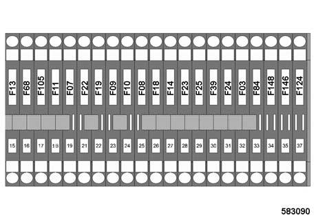
(17) 20A= (F105) Engine speed
(18) 15A= (F11) Front head lights **
(19) 15A= (F07) Hazard light
(21) 15A= (F22) Working headlights, rear
(22) 15A= (F19) Working headlights, rear
(23) 15A= (F09) Parking and tail light, left*
(24) 15A= (F10) Parking and tail light, right*
(25) 15A= (F08) Direction indicators*
(26) 10A= (F18) Pre-fuse for working head lights
(27) 15A= (F14) Engine solenoid
(28) 10A= (F23) Warning horn
(29) 10A= (F25) solenoid valve for driving and braking
(30) 15A= (F39) Main fuse for cabin
(31) 10A= (F24) Instruments
(32) 15A= (F03) Vibration
(33) 10A= (F148) Control MESX, potential 15*
Current only with the ignition switch in position "I" or when the engine is running.
*Optional equipment
(34) 10A= (F84) control, contact 54
(35) 15A= (F146) Control MESX, potential 30*
(37) 25A= (F124) Fuel pre-heating*
**Optional equipment
No. 23 =Toggle switch, cabin a = toggle switch for flashing beacon b = toggle switch for front windscreen wiper/ washer up= windscreen wiper moves to end position and stops. down= Switches on front windscreen wiping. c = toggle switch for rear windscreen wiper/ washer up= windscreen wiper moves to end position and stops. down= Switches on wiping of rear windscreen.
Push button= Front windscreen is sprayed during wiping.
Push button= Rear windscreen is sprayed during wiping.
Indicators and Controls
d = toggle switch for rear windscreen heating
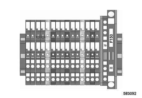
! Danger Fire hazard!
Do not use fuses with higher ampere ratings and do not bridge fuses.
(1) 15A= (F43) Wiper/washer, rear
(2) 15A= (F44) Wiper/washer, front
(3) 10A= (F130) Night light
(4) 25A= (F31) Cabin ventilator
(5) 10A= (F41) Flashing beacon
(6) 15A= (F144) Cab socket
(7) 15A= (F143) Rear windscreen heating
(8) 10A= (F42) Cab lights
Indicators and Controls
i = reading and dashboard light j = toggle switch for reading and dashboard light k = toggle switch for cabin light l = cabin light
No. 27 =Tachometer for diesel engine ** shows the rotational speed of the diesel engine. Scale value x 100 = revolutions per minute
No. 25 =Main fuse for battery
125A = (F00)
No. 28 =Vibration frequency display *** outer scale= Frequency in min-1 x 100 inner scale= Frequency in Hz
Shows the vibration frequency.
No. 26 =Speedometer * outer scale= km/h inner scale= mph
Shows the travel speed of the machine.
*Optional equipment
**Optional equipment
***Optional equipment
Fig. 41
No. 29 =EVIBdisplay * is a compaction measuring unit for continuous display of the load bearing characteristics (MN/m2) during the compacting pass.
EVIB value
Increase= higher load bearing capacity
Constant= end of compaction
i Note
Modular upgrading to BTM plus / BTM prof and/or BCM 05 possible.
Indicators and Controls
*Optional equipment
Indicators and Controls
3.3Display and control ele-
ments BTM *
1EVIBdisplay
2Display for jump operation
3Push button F5 START
4Push button F6 STOP
5Push button F7 PRINT (only BTM prof)
6Push button F8 DELETE
7Vibration frequency display
8Rotary switch setting of nominal value
9Push button F14 nominal value increase
10Push button F13 nominal value decrease
11not used
12not used
13not used
14not used
15not used
16not used
17Speed display
18Amplitude display
19Printer for measuring values (only BTM prof)
20Fault light
3.4Description of indicating and control elements BTM
i Note
The BTM plus can be upgraded to BTM prof and/ or BCM 05.
Surface covering dynamic compaction control (SCCC)
The BOMAG compaction measuring systems EVIB-meter (BEM) and Terrameter BTM plus/prof are integrated in the work process for continuous and surface covering evaluation of compaction and load bearing capacity of soils and non-bonded bearing courses.
The EVIB-value, designated as vibration modulus, with the unit MN/m2 is directly linked with the deformation modules EV1 or EV2 known from the plate load test acc. to DIN 18134.
No. 1 =EVIB-display
Display of the dynamic soil stiffness in MN/m2
No. 2 =Display for jump operation yellow symbol= Drum jumps red symbol= Drum jumps excessively or tumbles
Select a smaller amplitude, if necessary!
No. 3 =Button F5 START press= Starts recording of measuring values
Control field "F5" flashes green on the screen.
No. 4 =Button F6 STOP press= Stops recording of measuring values
The green control field "F7" PRINT on the screen lights up.
i Note
Depending on the measuring result the green control field "F5" CONTINUE or the red control field "F6" FINISHED will light up.
No. 5 =Button F 7 Print *
To print out the measuring data saved during the last pass press button F7 PRINT. short actuation= Line diagram long actuation ≥5 sec.= Bar chart
Control field F7 goes out and the measuring value printer starts to print out measuring data.
i Note
After the printing process has finished any amount of diagrams can be printed out by pressing the same button F7 (PRINT).
No. 6 =Button F8 DELETE press= All stored faults are deleted.
! Caution
If the increase of the measuring value is to be calculated on a track press button F8 DELETE only when changing the track.
No. 7 =Frequency display with vibration switched on this instrument shows the frequency (rotating speed) of the exciter shaft. No. 8 =Rotary switch P3 pre-setting of nominal values
The desired maximum dynamic stiffness modulus EVIB [MN/m2] can be pre-selected in 6 stages (45, 80, 100, 120,150 and Max.).
The selected value is shown on the screen in field „P3“
No. 9 =Button F14 increase of nominal value
With each actuation of the button the presetting is raised by one stage.
The selected value is shown on the screen in field „P3“
No. 10 =Button F13 reduction of nominal value
With each actuation of the button the presetting is reduced by one stage.
*only with BTM prof
Indicators and Controls
The selected value is shown on the screen in field
„P3“
No. 11 =Button F11 is not used
No. 12 =Button F12 is not used
No. 13 =Button F11 is not used
No. 14 =Rotary switch P1 is not used
No. 15 =Button F10 is not used
No. 16 =Button F9 is not used
No. 17 =Travel speed display
Shows the travel speed of the machine.
No. 18 =Amplitude display
This gauge shows the current vertical amplitude of the machine.
No. 19 =Printer for measuring values*
To print out the measuring data saved during the last pass press button (7) "PRINT".
No. 20 =Fault light
Infor the BOMAG After Sales Service if it lights up.
3.5Line diagram * (EVIB )
Indicators and Controls
1Pass-No.
2Travel direction
3Machine equipment (BTM 05/BTM-E)
4Software status of the measuring equipment
5Machine number
6Machine type
7Amplitude
8Maxiumum EVIB value
9Miniumum E VIB value
10Mean EVIB-value
11EVIB-change
12Medium frequency
13Mean travel speed
14Track length
15Raster division in longitudinal direction
16Marking (thick line) excessive jumping, tumbling of the drum
17Longitudinal raster line
18Measuring value raster line
19Diagram line
20Marking (thin line) jumping of the drum
3.6Description of line diagram * (EVIB )
No. 1 =Pass
Total number of measured passes on this track.
No. 2 =Travel direction
No. 3 =Machine equipment
No. 4 =Software status of the measuring equipment
No. 5 =Machine number
No. 6 =Machine type
No. 7 =Amplitude
This gauge shows the vertical amplitude the machine has worked with on this track.
No. 8 =Maxiumum EVIB value
No. 9 =Miniumum E VIB value
No. 10 =Mean EVIB-value
This gauge shows the vertical amplitude the machine is currently working with on this track.
No. 11 =EVIB-change
EVIB-change in %. This always refers to the previous pass in the same direction of travel.
No. 12 =Medium frequency
No. 13 =Mean travel speed shows the mean value of speed driven during this pass.
i Note
Always shows the same travel speed in order to avoid a falsification of the measuring results.
No. 14 =Track length
Measured track length between START and STOP.
No. 15 =Raster division in longitudinal direction
Is used to pinpoint individual measuring values on the measuring curve.
i Note
The raster lines mark measuring track sections of 5 m length.
Graduation of the measuring track (track length in printout) into fixed sections.
No. 16 =Marking of jump information i Note
Indicates excessive jumping/tumbling of the drum on the marked track section (thick line).
Select a smaller amplitude, if necessary!
No. 17 =Longitudinal raster line
No. 18 =Measuring value raster line
No. 19 =Diagram line
Shows the EVIB-value at any point of the rolled track. The raster line enables the location related assignment of the EVIB-value and the location of a fault (over or under compaction).
No. 20 =Marking of jump information
Indicates jumping of the drum on the marked track section (thin line).
Indicators and Controls
3.7Bar diagram * (EVIB )
The bar diagram differs from the line diagram only by the graphic representation of measuring values. In the bar diagram the mean values of 5 m sections are shown as bars. In addition, the EVIB changes of the individual 5 m sections are specified in percent after the second pass in the same travel direction.
*only BTM prof