27 minute read
MAINTENANCE SAFETY


Instructions are necessary before operating or servicing machine, Read Operation & Maintenance Manual, Handbook and signs (decals) on machine. Follow warnings and instructions in the manuals when making repairs, adjustments or servicing. Check for correct function after adjustments, repairs or service. Failure to follow instructions can cause injury or death.
W–2003–1089
Safety Alert Symbol:This symbol is used for important safety messages. When you see this symbol, follow the safety message to avoid personal injury or death.
Correct
Correct
Correct
Never service the Bobcat Hydraulic Excavator without instructions.
Use the correct procedure to lift and support the excavator. Always lift the blade fully before installing jackstands.
Cleaning and maintenance are required daily.
Wrong Wrong Wrong
Have good ventilation when welding or grinding painted parts. Wear dust mask when grinding painted parts. Toxic dust and gas can be produced.
Vent exhaust to outside when engine must be run for service. Exhaust system must be tightly sealed. Exhaust fumes can kill without warning.
Always lower the bucket and blade to the ground before doing any maintenance. Never modify equipment or add attachments not approved by Melroe Company.
Wrong Wrong Wrong
Stop, cool and clean engine of flammable materials before checking fluid. Never service or adjust machine with the engine running unless instructed to do so in the manual. Avoid contact with leaking hydraulic fluid or diesel fuel under pressure. It can penetrate the skin or eyes.
Never fill fuel tank with engine running, while smoking or when near open flame.
Keep body, jewelry and clothing away from moving parts, electrical contacts, hot parts and exhaust. Wear eye protection to guard from battery acid, compressed springs, fluids under pressure and flying debris when engines are running or tools are used. Use eye protection approved for type of welding. Keep rear door closed except for service. Close and latch door before operating the excavator.
Lead–acid batteries produce flammable and explosive gases. Keep arcs, sparks, flames and lighted tobacco away from batteries. Batteries contain acid which burns eyes or skin on contact. Wear protective clothing. If acid contacts body, flush well with water. For eye contact flush well and get immediate medical attention.
Maintenance procedures which are given in the Operation & Maintenance Manual can be performed by the owner/operator without any specific technical training. Maintenance procedures which arenot in this manual must be performed ONLY BY QUALIFIED BOBCAT SERVICE PERSONNEL. Always use genuine Bobcat replacement parts.
Maintenance work must be done at regular intervals. Failure to do so will result in excessive wear and early failures. The service schedule is a guide for correct maintenance of the Hydraulic Excavator.
Instructions are necessary before operating or servicing machine. Read Operation & Maintenance Manual, Handbook and signs (decals) on machine. Follow warnings and instructions in the manuals when making repairs, adjustments or servicing. Check for correct function after adjustments, repairs or service. Failure to follow instructions can cause injury or death. W–2003–1089
Engine Air CleanerCheck and empty dust cap as required.
Engine Oil Check the oil level & add oil as needed.
Engine Coolant SystemCheck radiator coolant level.
Indicator Lights Check for correct operation.
Operator Canopy Check the fastening bolts, nuts, & condition of cab/canopy.
Seat Belt Check the condition & that fasteners are tight.
Safety Signs (Decals)Check for damaged signs (decals) and safety tread. Replace as needed.
Tracks Check & adjust tension.
Hydraulic ReservoirCheck fluid level.
All Machinery Pivot PointsLubricate 22 grease fittings.
Fuel Tank/Fuel FilterDrain water & sediment from fuel tank/fuel filter.
Swing Circle Lubricate two grease fittings.
Swing Pinion Lubricate one grease fitting.
Spark Arrestor MufflerClean spark chamber.
Engine Oil & Filter Replace oil & filter element.
Alternator/Fan Belt Check & adjust tension.
Fuel Filters Replace filter element.
Battery Check cables, connections and electrolyte level. Add distilled water as needed.
Air Cleaner ElementReplace Air Cleaner Element
Hydraulic Filter Replace filter element.
Cooling System Clean the radiator fins.
Alternator & StarterCheck the condition and connections.
Engine Valve ClearanceCheck and adjust as needed
Case Drain Return FilterReplace the filter (if equipped).
Cooling System Drain, flush & add new coolant to the cooling system.
Hydraulic Tank Change the fluid, clean fill neck strainer.
Case Drain Return ScreenClean the screen with solvent (if equipped).
Final Drive Case Change the gear lube.
*After the first 50 hours of machine operation do the following:
• Replace the engine oil and filter.
• Check the condition of the alternator/fan belt.
• Replace hydraulic filter.
**After the first 100 hours of machine operation do the following procedures:
• Change oil in final drive case.
After the first 250 hours of machine operation do the following procedures:
• Check and adjust valve clearance.
Avoid Injury
Never service or adjust the machine when the engine is running unless instructed to do so in this manual.
W–2012–0290
Keep the engine cover closed when operating the machine.
W–2141–0189
Open the engine cover to service the engine. Pull on the latch and lift the engine cover up until it is fully raised[A]


Air Cleaner Service
See the SERVICE SCHEDULE Page 27 for the correct service interval.
Service the air cleaner as follows:
Daily Check:
Loosen the clamp on the air cleaner [B]

Remove the cover (Item 1) [C] and the dust cup (Item 2) [C]. Empty dust cup. Visually inspect the filter element. Do not remove element unless plugged and replacement is necessary.
Filter Replacement:
Remove the wing nut (Item 3) [C]
Remove the filter element [D]
Check the air cleaner housing for damage.
Wipe the canister and the seal surface clean with a clean cloth. Do Not use compressed air.
Check the seal (Item 1) [D] for damage. Do not use an air filter element with a damaged seal.
Install a new air filter element. Install and tighten thewing nut.
Install the dust cup and cover so the arrow points up.
Check that all the air cleaner hose clamps are tight.
Fuel System
Use Number 2 diesel fuel in the engine. During very cold temperatures, Number 1 fuel can be used.
Stop and cool the engine before adding fuel. NO SMOKING! Failure to obey warnings can cause an explosion or fire.
W–2063–0887
Fuel System Maintenance
The fuel level in the tank is indicated by the fuel gauge (Item 1) [A] when the ignition switch is in the ON position.

NOTE:When the fuel level reaches the 1/8 fuel setting, the low fuel light (Item 2) [A] will come ON to alert the operator of this condition.
Use the key to unlock the fuel fill door [B]


Turn the fill cap (Item 1) [C] to remove it. Use a clean, approved safety container to add fuel to the tank.
Add fuel only in an area that has a free movement of air and no flames or sparks. NO SMOKING!
After the tank is full, install and tighten thefuel cap. Close and lock the fuel door.
Always clean up spilled fuel or oil. Keep heat, flames, sparks or lighted tobacco away from fuel and oil. Failure to use care around combustibles can cause explosion or fire which can result in injury or death.
W–2103–1285

To remove the water and sediment from the fuel tank, turn the upperstructure until the fuel tank is centered between the rear tracks.
Slowly open the drain valve (Item 1) [D] at the bottom of the fuel tank. Drain the contaminated fuel into a container. When clean fuel flows from the drain valve, close the valve.
FUEL SYSTEM (Cont’d)
Fuel Filters
See the SERVICE SCHEDULE Page 27 for the correct service intervals.
To remove water from the filter, open the drain valve (Item 1) [A] at the bottom of the fuel filter. Drain contaminated fuel into a container.
Use a filter wrench to remove the fuel filter [A]


Replace the filter and hand tighten only.
Removing Air From The Fuel System
After replacing the fuel filter or after running out of fuel, air must be removed from the fuel system.
Open the vent screw (Item 1) [B] on the injection pump.
Open the bleed screw on the top of the fuel filter housing (Item 1) [C].
Squeeze the primer bulb (Item 1) [D] to fill the filter.
When fuel, free of air bubbles emerges from the filter housing, close the bleed screw.
Leave the vent on the injection pump open slightly.
Start the engine. When the engine runs smoothly, close the vent screw on the injection pump.
NOTE:If engine fails to start after above procedure is performed, it will be necessary to bleed the injector lines, do the following:
1.Loosen the three injector line lock nuts, one turn.
2.While cranking engine, as fuel emerges from injector lines, slowly tighten the injector line lock nuts.


Engine Lubrication System

Check the engine oil every day. Stop the engine. Open the engine cover.
Remove the dipstick [A].
Keep the oil level between the marks on the dipstick. Use a good quality motor oil that meets the correct API Service Classification of CD or better. (See FUEL, COOLANT AND LUBRICATION Chart Page 58.)
Engine Oil And Filter Replacement
See the SERVICE SCHEDULE Page 27 for the correct service interval.
Use the following procedure to change the oil and filter: Run the engine until it is at operating temperature.
Turn the upperstructure so there is clearance for the engine oil drain plug. Stop the engine.
Remove the drain plug (Item 1) [B]. Drain the oil into a container.
Remove the oil filter (Item 1) [C], using a filter wrench. Clean the filter housing surface. Put clean oil on the filter gasket. Install the new filter and hand tighten only.


Install and tighten the oil drain plug.
Clean the area around the dipstick and remove the dipstick [A]
Remove the dipstick tube cap [D]. Use a funnel and put 4.5 quarts (4,3 L) of oil into the engine. (See FUEL, COOLANT AND LUBRICATION Chart Page 58).
Start the engine and let it run for several minutes. Stop the engine. Check for leaks at the oil filter and the oil drain plug.
Check the oil level and add oil as needed if it is not at the top mark on the dipstick.
ENGINE LUBRICATION SYSTEM (Cont’d)
Engine Oil And Filter Replacement (Cont’d)
The valve cover oil fill cap can be used for adding oil in place of the dipstick tube, but use a protective, heat resistant shield over the muffler to protect yourself from the hot muffler [A]
COOLING SYSTEM
Coolant Level
When the engine is cool, remove the radiator cap [A].
The coolant level must be 3/4–1 inch (19–25 mm) below the filler neck.

If the coolant level is low, add premixed coolant to the radiator. (See FUEL, COOLANT AND LUBRICATION chart Page 58 for coolant mixture information.)
Coolant Replacement
Do not remove radiator cap when the engine is hot. You can be seriously burned.
W–2070–1285
Wear safety glasses to prevent eye injury when any of the following conditions exist:
• When fluids are under pressure.
• Flying debris or loose material is present.
• Engine is running.
• Tools are being used.
W–2019–1285
Turn the upperstructure so there is access to the engine and radiator from between the tracks. Stop the engine.

When the engine is cool, loosen and remove the radiator cap [B]

Open the radiator drain valve (Item 1) [C]
Drain all the coolant from the system.
When all the coolant is removed, close the drain valve. Fill the radiator with the premixed coolant until it is full. (See FUEL, COOLANT AND LUBRICATION chart Page 58 for coolant mixture information.)
Run the engine at idle speed for about 5–10 minutes to remove the air from the cooling system (leave the radiator cap off during this operation).
Stop the engine. Check the coolant level and add as needed to bring it 3/4–1 inch ( 19–25 mm) below the filler neck. Install the radiator cap and tighten.
NOTE:All cab equipped excavators have an air baffle under the radiator that is bolted to the bottom of the upperstructure [D].

Alternator Belt Adjustment
To adjust the belt tension, use the following procedure: Stop the engine. Open the engine cover.

The belt should deflect about 5/8 inch (16 mm) when pressed between the water pump pulley and crankshaft pulley with approximately 22 lbs. (10 kg) pressure [A]

If the tension is not correct, loosen the alternator mounting bolt.
Loosen the adjustment bolt [B]
Move the alternator until the belt tension is correct.
Tighten the adjustment bolt and mounting bolt.
Replace the belt if it has stretched or there are cracks in the belt. Check the pulley grooves, make sure the belt is not in contact with the bottom of the grooves in the pulleys.
Electrical System
The excavator has a 12 volt, negative ground electrical system.

Fuses
The following fuses protect these circuits from overload:
1.25 amp: This fuse protects the light switch circuit and it supplies power to the cab (if equipped) [A].

2.25 amp: This fuse protects the ignition circuit, the auxiliary power outlet and the hourmeter [A]
3. 25 amp: This fuse protects the heater circuit (if equipped) and the rear accessory wire [A]
4.5 amp: This fuse protects the cab electrical circuit; wipers, washer and interior light (if equipped) [B]
Replace all fuses with the same type and capacity.
NOTE:Before replacing any fuse, find and fix the problem that caused the fuse to blow. Make sure the key switch is in the OFF position before replacing the fuse.

Service The Electrical System
Open the engine cover [C]
The battery cables must be clean and tight [D]. Remove any acid or corrosion from the battery and cables using a sodium bicarbonate and water solution. Cover the battery terminals and cable ends with battery saver grease.
Check for broken or loose connections.
If the battery cables are removed for any reason, disconnect the negative (–) cable first and when installing the battery cables, make the last connection the negative (–) cable to the battery.
With factory equipped battery, no maintenance is needed as this is a maintenance free battery.
If the machine has a Melroe parts replacement battery installed, check the electrolyte level in the battery.
If it is lower than 1/2 inch (13 mm) above the plates, add distilled water only.
Batteries contain acid which burns eyes and skin on contact. Wear goggles, protective clothing and rubber gloves to keep acid off body.
In case of acid contact, wash immediately with water. In case of eye contact get prompt medical attention and wash eye with clean, cool water for at least 15 minutes.
If electrolyte is taken internally drink large quantities of water or milk! DO NOT induce vomiting. Get prompt medical attention.
W–2065–1296
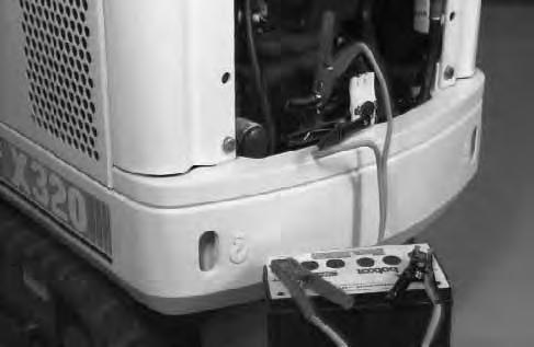
ELECTRICAL SYSTEM (Cont’d) Using A Booster Battery (Jump Starting)
If it is necessary to use a booster battery to start the engine. BE CAREFUL!
Make sure the swing lock is in the engaged position. The key switch must be in the OFF position. The booster battery must be 12 volt.

Open the engine cover [A].
Connect the end of the first cable to the positive (+) terminal of the booster battery. Connect the other end of the same cable to the positive (+) terminal (Item 1) [B] & [C]
Connect the end of the second cable to the negative (–) terminal of the booster battery. Connect the other end of the same cable to the frame (Item 2) [B] & [C]
NOTE:Also see Cold Starting Procedure Page 15.
Start the engine. After the engine is running, remove the negative (–) cable (Item 2) [B] connected to the frame first. Disconnect the cable from the starter terminal (Item 1) [B]
If jump starting the excavator from a second machine:
When jump starting the excavator from a battery installed in a second machine. Make sure that the second machine is NOT running while using the glow plugs. High voltage spikes from a running machine can burn out the glow plugs.
I–2060–0195
Keep arcs, sparks, flames and lighted tobacco away from batteries. When jumping from booster battery make final connection (negative) at engine frame.
Do not jump start or charge a frozen or damaged battery. Warm battery to 60° F. (16° C.) before connecting to a charger. Unplug charger before connecting or disconnecting cables to battery. Never lean over battery while boosting, testing or charging.
Battery gas can explode and cause serious injury.
W–2066–1296
Damage to the alternator can occur if:
• Engine is operated with battery cables disconnected.
• Battery cables are connected when using a fast charger or when welding on the loader (Remove both cables from the battery).
• Extra battery cables (booster cables) are connected wrong.
I–2023–1285
ELECTRICAL SYSTEM (Cont’d)
Removal And Installation Of The Battery
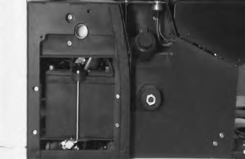
Open the hydraulic tank access door [A].


Remove the four bolts from the right side cover [A]
Remove the side cover.
Disconnect the negative (–) cable (Item 1) [B] first.
Disconnect the positive (+) cable (Item 2) [B]
Remove the two nuts (Item 1) [C] and remove the hold down clamp (Item 2) [C]
Remove the battery from the compartment [D].
Always clean the terminals and the cable ends, even when installing a new battery.
Install the battery. Install the holddown clamp and the two nuts.
NOTE:Do not touch any metal to the battery terminals.
Connect the battery cables. Connect the negative (–) cable (Item 1) [B] last to prevent sparks at the the terminal.
Batteries contain acid which burns eyes and skin on contact. Wear goggles, protective clothing and rubber gloves to keep acid off body.
In case of acid contact, wash immediately with water. In case of eye contact get prompt medical attention and wash eye with clean, cool water for at least 15 minutes.
If electrolyte is taken internally drink large quantities of water or milk! DO NOT induce vomiting. Get prompt medical attention.
W–2065–1296
HYDRAULIC SYSTEM Checking And Adding Fluid
To check and add hydraulic fluid to the reservoir, use the following procedure:

Prior to checking the hydraulic fluid level, retract the arm and bucket cylinder, put the bucket on the ground and raise the blade.
Put the machine on a flat level surface.

Retract the arm and bucket cylinders, put the bucket on the ground and raise the blade. Stop the engine.
The hydraulic fluid level must be visible in the center of the sight gauge (Item 1) [A]
If the fluid level is not correct, open the hydraulic tank access door [B]
Remove the reservoir cap [C].
Remove the screen from the fill neck and inspect it for damage [D]. The screen must be installed in fill neck when adding oil.
Add the correct fluid to the reservoir until it is in the center of the sight gauge [A]. (See FUEL, COOLANT AND LUBRICANTS Chart Page 58).
Install the reservoir cap.
HYDRAULIC SYSTEM (Cont’d)
Diagnostic Couplers
The diagnostic couplers are located on each section of the hydraulic pump (Item 1) [A]


The couplers can be used to check circuit pressures. (Refer to the Service Manual.)
Prior to checking the hydraulic fluid level, retract the arm and bucket cylinder, put the bucket on the ground and raise the blade.
Replacement of the Hydraulic Filter
See the SERVICE SCHEDULE Page 27 for the correct service interval.
Open the engine cover.
Use a filter wrench and remove the filter element (Item 1) [B]
Clean the housing where the filter gasket makes contact. Put clean hydraulic fluid on the gasket. Install the new filter element and hand tighten only.
Start the engine. Run the machine through the hydraulic functions. Stop the engine. Check the fluid level at the reservoir and add as needed. Check around the filter for leaks.
Hydraulic Reservoir
Replacement Of The Hydraulic Fluid.
See the SERVICE SCHEDULE Page 27 for the correct service interval.
Move the upperstructure so there is clearance for the reservoir drain between the tracks.
Retract the arm and bucket cylinders, lower the bucketto the ground. Stop the engine.
Remove the hydraulic filter element [B]
Remove the drain plug (Item 1)[C] from the bottom of the reservoir.
Drain the fluid into a container.
Install the drain plug.
Install a new filter. (See information above.)
Add the correct fluid to the reservoir untilit is visible in the sight gauge (approximately 3.75 gals. [14,2 L.] to fill only the reservoir). (See FUEL, COOLANT AND LUBRICANTS Chart Page 58.)
Always clean up spilled fuel or oil. Keep heat, flames, sparks or lighted tobacco away from fuel and oil. Failure to use care around combustibles can cause explosion or fire which can result in injury or death.
HYDRAULIC SYSTEM (Cont’d) Filter Screen (Factory Installed)
The 100 mesh filter in the port block, removes contamination from the fluid returning from the travel motors and swing motor.
When making repairs on hydrostatic and hydraulic systems, clean the work area before disassembly and keep all parts clean. Always use caps and plugs on hoses, tubelines and ports to keep dirt out. Dirt can quickly damage the system.

Drain hydraulic reservoir.

Remove the rear hose and the rear fitting from the drain block [A].
Remove the 100 mesh screen filter from the drain block [B]
NOTE:Use finger tip to dislodge the filter screen for removal. Do not use a sharp object as screen will be damaged.
Wash the screen in solvent and dry with compressed air. Inspect the screen for damage and replace asnecessary.
Reinstall the screen with the washer surface of the filter toward the fitting.
Reinstall the fitting.
Reinstall the return line.
Fill the hydraulic reservoir with hydraulic fluid.
In–Line FIlter (Service Replacement)

Remove the four bolts from the right side cover [C] Remove the right side cover.
Remove the in–line filter (Item 1) [D] and install a new in–line filter.
Lubrication Of The Hydraulic Excavator
Lubricate the Hydraulic Excavator as specified in the SERVICE SCHEDULE Page 27 for the bestperformance of the machine.
Always use a good quality lithium based multi–purpose grease when lubricating the machine. Apply the lubricant until extra grease shows.
Ref.Description (# of Fittings)
1.Blade Cylinder Rod End, every 8–10 hours (1)[A]
2.Blade Pivots, every 8–10 hours (2) [A].
3.Blade Cylinder Base End, every 8–10hours (1) [A].
4.Boom Swing Cylinder Rod End, every 8–10hours (1) [B].
5.Boom Cylinder Base End, every 8–10 hours (1) [B]
6.Boom Base Pivot, every 8–10 hours (1) [B]
7.Swing Circle Pinion, every 50 hours (1)[B]. Install four pumps of grease from a grease gun into the grease fitting. Rotate the upperstructure 180o and install four more pumps of grease into the grease fitting.


8.Boom Swing Bracket Pivot, every 8–10 hours (2) [C]
9.Frame Swing Bracket Pivot, every 8–10 hours (1) [C]

10.Boom Cylinder Rod End, every 8–10 hours (1)[D]
11.Arm Cylinder Base End, every 8–10 hours (1)[D].
12.Arm Cylinder Rod End, every 8–10 hours (1) [D]
13.Arm Base Pivot, every 8–10 hours (1) [D].
14.Bucket Cylinder Base End, every 8–10 hours (1) [D].
LUBRICATION OF THE HYDRAULIC EXCAVATOR (Cont’d)
Ref.Description (# of Fittings)
15.Bucket Cylinder Rod End, every 8–10 hours (1) [A]
16.Bucket Link Pivots, every 8–10 hours (2) [A]
17.Bucket Pivots, every 8–10 hours (3) [A].
18.Boom Swing Cylinder Base End, every 8–10 hours (1) [B].
NOTE:Access to the grease fitting is from under the upperstructure, right side.


19.Swing Circle Ball Bearing, every 50 hours (2) [C].
NOTE:Do not over grease the swing circle or damage to the seal could result. Install four to five pumps of grease from a grease gun into each of the two grease fittings. Rotate the upperstructure 90o and install four to five pumps of grease into each of the two grease fittings.
Final Drive Case

Checking Oil Level
Put the machine on a flat level surface.
Position the plugs (Item 1) [A] parallel to the ground.
Remove one of the plugs (Item 1) [A]
Add gear lube through the hole if the gear lube level is below the hole. (See FUEL, COOLANT AND LUBRICANT Chart Page 58.)

Install and tighten the plug.
Repeat the procedure for the other side.
Replacing Final Drive Case Oil
See the SERVICE SCHEDULE Page 27 for the correct service interval.
Put the machine on a flat level surface with the plugs positioned as shown in figure [B].
Remove the bottom plug (Item 1) [B] and top plug (Item 2) [B].
After all the gear lube is removed, install and tighten the bottom plug.
Add 0.300 quarts (0,3 L) of gear lube to the top plug hole. Install the plug
Move the excavator until the plugs are positioned parallel to the ground [A]
Use the same procedure as for Checking Oil Level (see information above) add additional oil as needed.
Repeat the procedure for the other side.
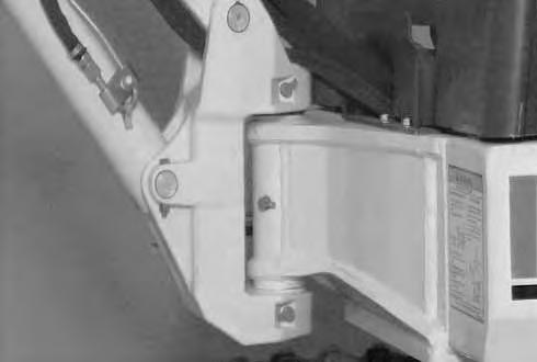
NOTE:The wear of the parts on the undercarriage vary with the working conditions and the different types of soil conditions. It is necessary to inspect track tension to maintain the correct tension. (See SERVICE SCHEDULE Page 27 for the correct service interval.)

Adjustment
Raise one side of the machine (approximately 4 inches) using the boom and arm as shown in [A].

Raise the blade fully and install jackstands under the blade and the track frame [A].
Stop the engine.
Avoid Injury
Keep fingers and hands out of pinch points when checking the track tension.
W–2142–0189
Measure the distance between the frame and the top of the track. If the distance is between 2.25–2.50 inches (57–63 mm), the track tension is correct [B]
If not, loosen one bolt and remove the other bolt from the cover [C].
Add grease to the fitting(Item 1) [D] until the track tension is correct.

If track tension is too tight, decrease the track tension pressure by loosening the bleed screw (Item 2) [D] (maximum of 1 turn) and allow grease to flow out of the bleed screw. When the tension is correct, tighten the bleed screw.
Repeat the procedure for the other side.
If the track tension is still loose after adjusting to theabove mentioned limit, it indicates the track is worn. See your dealer for repairs.
Avoid Injury
Do not loosen the grease fitting more than one complete rotation. Also, be careful not to loosen any part other than the grease fitting. If the grease fitting or any part is loosened too much, it can fly off under high pressure. If the grease does not ooze smoothly, try moving the machine back and forth for a short distance.
W–2143–0189
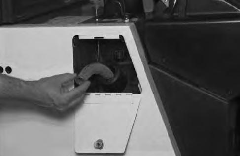
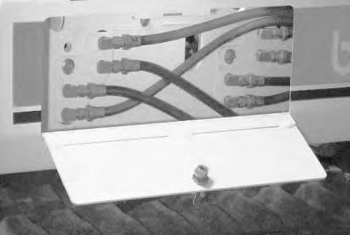
Joystick Control Change
ISO To Standard Control Pattern
To change from ISO to STANDARD joystick controls, do the following procedure:
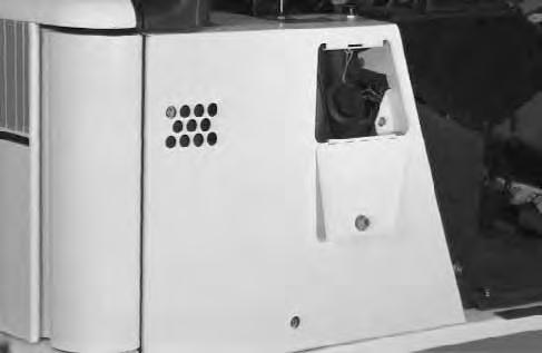
Open the tool box door.
Remove the hose cover plate.
Remove the bottom plate from the tool box.
Mark and remove hoses (Items 1, 2, 3 & 4) [A] from the bulkhead elbows.
Install the hoses onto the new locations as shown (Items 1, 2, 3 & 4) [B]
Install new decals (P/N 6587427) onto the right hand console and (P/N 6587428) onto the left hand console.
After exchange of the hoses, the right joystick will now control arm (raise and lower) and the bucket (curl). The left joystick will control the boom (raise andlower) and the upperstructure (swing).
See Service Manual for additional information.
Standard To ISO Control Pattern
To change from STANDARD to ISO joystick controls, do the following procedure:
Open the tool box door.
Remove the hose cover plate.
Remove the bottom plate from the tool box.
Mark and remove hoses (Items 1, 2, 3 & 4) [C] from the bulkhead elbows.
Install the hoses onto the new locations as shown (Items 1, 2, 3 & 4) [D].
Install new decals (P/N 6587425) onto the right hand console and (P/N 6587426) onto the left hand console.
After exchange of the hoses, the right joystick will now control boom (raise and lower) and the bucket (curl). The left joystick will control the arm (raise and lower) and the upperstructure (swing).
See Service Manual for additional information.
320 (S/N 511720001–511721115)
ADVERTENCIA (SPANISH)
EVITE UN ACCIDENTE QUE PUEDE SER MORTAL
TRANSPORTE DE LA EXCAVADORA
• Utilice rampas de acerp de superficie antideslizante y con rebordes.
• Asegure las rampas a la plataforma de vehiculo.
• Accione el freno de estacionamiento.
• Asegure las ruedas delanteras y traseras.
• No ponga las rampas con mas de 15 ° de inclinacion.
• El extremo superior de la rampa debe quedar al nivel de la plataforma.
• Active el pasador de bloqueo del giro antes de mover la máquina.
• Coloque calzos bajo las orugas y disponga cadenas de sujeción.
IZADO DE LA EXCAVADORA
• Los dispotivos de izado deben tener la capacidad adecuada al peso de la máquina.
• Mantener el centro de gravedad y el equilibrio al proceder al izado.
• No girar el aguilón o el chasis superior. Embragar la palanca de giro.
• No izar nunca estando el operador en la máquina.
Vea la indicaciones en los manuales de Manejo y de Mantenimiento.
AVERTISSEMENT (FRENCH)
EVITER LES BLESSURES OU LA MORT
TRANSPORT DE LA MACHINE
• Utiliser des rampes en ancier avec des rebords etune surface antidérapante.
• Attacher les rampes au plancher de la remorque.
• Enclencher le frein de stationnement.
• Caler les roues à l’avant et à l’arrière.
• L’inclinaison de la rampe ne doit pas dépasser 15° .
• L’extrémité de la rampe doit être dans l’alignement du plancher de la remorque.
• Enclencher l’axe de verrouillage d’orientation avant le chargement ou le transport.
• Attacher le pelle avec des chaïnes et bloquer les chenilles.
LEVAGE DE LA MACHINE
• Les câbles de levage au les élingues en nylon dolvent être capables de supporter le polds de la machine.
• Maintenir le centre de gravité à l’endroit voulu et toujours garder l’équillibre pendant le levage.
• Ne jamais faire tourner la flèche ni la superstructure. Enclencher l’axe de verrouillage d’orientation.
• Ne jamais lever la pelle quand l’opérateur a’y trouve.
Se reporter au manuel de l’Opérateur et d’Entretien pour plus de renseignements.
Advertencia
• No tratar de levantar o sostener cualquier carga mayor que estos valores nominales en sus radios de carga y altura especificos.
• El peso de las eslingas y de los dispositivos auxiliares de elevación debe deducirse a partir de la carga nominal para determinar la carga neta que puede levantarse.
• La sobrecarga provoca que la máquina se ladee y puede resultar en lesiones o la muerte.
Radio de elevación (r) mm (pulgadas)
Modelo 320
Las especificaciones se ajustan a las normas SAE (Sociedad de Ingenieros en Automotores) cuando así corresponda. Las especificaciones se hallan sujetas a modificaciones sin previo aviso.
El punto de elevación es el punto de articulación del cucharón, 97 lbs. (44 kg) con en el cucharón totalmente recogido.
Radio de elevación (r) mm (pulgadas)
*Capacidad de elevación hidráulica nominal.
Radio de elevación (r) mm (pulgadas)
Capacidad de elevación nominal paralela a las orugas (cuchilla del cucharón hacia abajo) kg (lb) Capacidad de elevación nominal perpendicular a las orugas (cuchilla del cucharón hacia abajo) kg (lb) Capacidad de elevación nominal paralela a las orugas (cuchilla del cucharón hacia abajo) kg (lb) suelo
Avertissement
• Ne pas tenter de soulever ni de maintenir une charge supérieure aux valeurs nominales ci–dessous, à leurs hauteurs et rayons de portée respectifs.
• Il faut déduire de la charge nominale le poids des élingues et des accessoires de levage auxiliaires pour pouvoir déterminer la charge nette qui peut être soulevée.
• Une surcharge fera basculer l’engin et risque de causer des blessures ou la mort.
Hauteur de levée mm (po) h
Rayon de levée – mm (po)
Capacité de levage nominale à l’extrémité Lame baissée – kg (lb)
Modèle 320
Les caractéristiques sont conformes aux normes SAE, le cas échéant. Les caractéristiques peuvent faire l’objet de changements sans préavis.
Le point de levée est situé à l’axe d’articulation du gond du godet, avec godet de 44 kg (97 lb) complètement replié.
*Capacité de levage hydraulique nominale.
Rayon de levée – mm (po) Rayon de levée – mm (po)
Capacité de levage nominale à l’extrémité Lame levée – kg (lb)
Capacité de levage nominale sur le côté Lame levée – kg (lb)
PROGRAMA DE SERVICIO (SPANISH)
8–10 HORAS
1.Verificar el nivel del refrigerante.
2.Verificar el nivel de aceite del motor.
3.Verificar el nivel del combustible.
4.Verificar el nivel del fluido hidráulico.
5.Verificar y vaciar el recipiente de polvo del depurador de aire.
6.Verificar y ajustar la tensión de la oruga.
7.Verificar la correcta operación de las luces indicadoras.
8.Verificar el pestillo de fijación, las tuercas y el estado de la cabina o cubierta.
9. Verificar el estado del cinturón de seguridad y que las trabas estén ajustadas.
10.Verificar si hay daños en las señales (calcomanía). Reemplazar según sea necesario.
11.Agregar grasa en toda la retroexcavadora, los pasadores de giro de la pala y los pasadores de giro del cilindro (22 lugares).
5O PRIMERAS HORAS
12.Reemplazar el filtro del fluido hidráulico.
13.Verificar el estado de la correa del ventilador.
5O HORAS
14.Agregar grasa al piñón de oscilación.
15.Agregar grasa al círculo de oscilación.
16.Drenar el agua y el sedimento del tanque de combustible.
100 HORAS
17.Reemplazar el aceite y el filtro del motor.
18.Verificar y ajustar la correa del ventilador.
PRIMERAS 250 HORAS
19.Verificar y ajustar la separación entre las válvulas del motor.
250 HORAS
20.Verificar el nivel de agua en la batería y limpiar los extremos de los cables.
21.Reemplazar el filtro hidráulico.
22.Reemplazar los filtros del combustible.
23.Reemplazar el dispositivo depurador de aire.
500 HORAS
24.Verificar las aletas del radiador.
25.Verificar el alternador y el arrancador.
26.Verificar y ajustar la distancia entre las válvulas del motor.
1000 HORAS O CADA 6 MESES
27.Reemplazar el filtro hidráulico.
28.Reemplazar el fluido hidráulico. Limpiar el depósito.
29.Drenar y lavar el sistema de enfriamiento y reemplazar el refrigerante.
PLAN D’ENTRETIEN 320 (FRENCH)
TOUTES LES 8–10 HEURES
1.Vérifier le niveau de liquide de refroidissement.
2.Vérifier le niveau d’huile moteur.
3.Vérifier le niveau de carburant diesel.
4.Vérifier le niveau d’huile hydraulique.
5.Vérifier l’état du collecteur de poussière du filtre à air et le vider.
6.Vérifier et régler la tension des chenilles.
7.Vérifier le bon fonctionnement des lampes–témoins.
8.Vérifier le serrage de la boulonnerie ainsi que l’état de la cabine ou de l’auvent.
9.Vérifier l’état de la ceinture de sécurité et si ses dispositifs de fixation sont biens serrés.
10.Vérifier si les autocollants sont endommagés. Les remplacer s’il y a lieu.
11.Graisser tous les axes d’articulation de la pelle rétrocaveuse, de la lame et du vérin (22 points).
PREMIÈRES 50 HEURES
12.Remplacer le filtre à huile hydraulique.
13.Vérifier l’état de la courroie de ventilateur.
TOUTES LES 50 HEURES
14.Graisser le pignon de rotation.
15.Graisser la couronne de rotation.
16.Drainer l’eau et les sédiments du réservoir à carburant.
TOUTES LES 100 HEURES
17.Remplacer l’huile moteur et le filtre à huile moteur.
18.Vérifier la courroie de ventilateur et la régler s’il y a lieu.
PREMIÈRES 250 HEURES
19.Vérifier et régler le jeu des soupapes du moteur.
TOUTES LES 250 HEURES
20.Vérifier le niveau d’électrolyte de la batterie et nettoyer les extrémités des câbles.
21.Remplacer le filtre à huile hydraulique.
22.Remplacer les filtres à carburant.
23.Remplacer l’élément de filtre à air.
TOUTES LES 500 HEURES
24.Nettoyer les ailettes du radiateur.
25.Vérifier l’alternateur et le démarreur.
26.Vérifier et régler le jeu des soupapes du moteur.
TOUTES LES 1000 HEURES OU TOUS LES 6 MOIS
27.Remplacer le filtre à huile hydraulique.
28.Vidanger et nettoyer le réservoir d’huile hydraulique. Remplacer l’huile hydraulique.
29.Vidanger et rincer le circuit de refroidissement. Remplacer le liquide de refroidissement.
ADVERTENCIA (SPANISH)
EVITE UN ACCIDENTE QUE PUEDE SER MORTAL
Lea detenidamente el Manuel de Manejo antes de utilizar la cargadora.
Utilice el cinturón bien ajustado. Accione los mandos únicamente ocupando el asiento de la máquina.
Trabaje siempre con una cabina de protección. No altere los equipos. No utilice implementos que no estén aprobados por Melroe.
No circule por terreno escarpado o superficies inestables.. No utilice nunca los mandos como agarraderos para subir a la máquina.
Asegúrese de que no hay nadie dentro del radio de giro. No circule ni gire con la cuchars desplegada.
Enpendientes, circule con la parte más pesada hacia arriba.
Para extender la pluma a un lado:
• Lleve la carga apenas levantada.
• Gire lentamente.
• No sobrepase la capacida nominal véase la table de capacidades).
ANTES DE BAJAR DEL EQUIPO:
1.Baje el implemento al suelo.
2.Pare el motor.
AVERTISSEMENT (FRENCH)
EVITER DES BLESSURES OU LA MORT
Lire et comprendre le Manuel de l’operateur avant d’utiliser la pelle.
Serrer spogneusement la ceinture de sécurite. N’actionner les commandes ou à partir du siége de l’operateur.
Toujours utiliser une cabine de protection. Ne jamais modifier l’equipement niajouter des accessoires non aprouves par Melroe.
Eviter les endroits escarpes ou les surfaces instables.
Ne jamais se servir des commandes pour monter dans la cabine.
S’assurer quil n’y a personne dans la zone de balayage maximal.
Ne jamais rouler ou tourner avec le godet allongé.
En pente, maintenir le côte lourd vers le haut.
En cas de déport du côte des chenilles:
• Tenir la charge vers le bas.
• Faire tourner lentement.
• Ne pas dépasser la capacité de charge – se reporter au tableau des charges de levage.
AVANT DE QUITTER LA PELLE:
1.Abaisser l’equipement au sol.
2.Arréter le moteur.
ADVERTENCIA (SPANISH)
EVITE UN ACCIDENTE QUE PUEDE SER MORTAL
No afloje el engrasador más de 1–1/2 vuelta. No afloje ninguna otra pieza. Está cargado con grasa a presión.
AVERTISSEMENT (FRENCH)
EVITER DES BLESSURES OU LA MORT
Ne pas deserrer le graisseur de plus de 1–1/2 tour.
Ne pas deserrer une pièce autre que le graisseur. La graisse se trouve sous haute pession.
ADVERTENCIA (SPANISH)
NO SE EXPONGA A SUFRIR LESIONES
• NO ABRA LA PUERTA CON EL MOTOR EN MARCHA, SOLO SI ES NECESARIO PARA EL MANTENMIENTO.
• NO SE ACERQUE AL VENTILADOR NI A OTRAS PIEZAS MOVILES.
AVERTISSEMENT (FRENCH)
ÉVITER LES BLESSURES
• NE PAS OUVRIR LA PORTE D’ACCÉS AU MOTEUR QUAND IL TOURNE, SAUF POUR ENTRETIEN.
• SE TENIR À L’ÉCART DU VENTILATEUR ET DES ORGANES MOBILES.
ADVERTENCIA (SPANISH)
EL CILINDRO CONTIENE GAS BAJO ALTA PRESION. EL ABNRIR EL CILINDRO PUEDE SOLTAR LA VARILLA Y CAUSAR HERIDAS O LA MUERTE.
AVERTISSEMENT (FRENCH)
LES VERINS RENFERMENT UN GAZ SOUS PRESSION. NE JAMAIS OUVRIR UN VERIN CAR LA TIGE RISQUE DE S’ECHAPPER BRUTALEMENT ET DE CAUSER DES BLESSURES OU MEME LA MORT.
ADVERTENCIA (SPANISH)
• NO AFLOJE EL TAPON DE LLENADO SI EL MOTOR ESTA CALIENTE.
• SE EXPONE A SUFRIR UNA QUEMADURA GRAVE.
AVERTISSEMENT (FRENCH)
• NE PAS DESSERRER LE BOUCHON DE VIDANGE QUAND LE MOTEUR EST CHAUD.
• DANGER DE BRÛLURES GRAVES.
Hydraulic Excavator Specifications
Machine Dimensions
• All dimensions are shown in inches. Respective metric dimensions are given in millimeters enclosed by parentheses.
• Where applicable, specifications conform to SAE standards. Specifications are subject to change without notice.
• All dimensions are shown in inches. Respective metric dimensions are given in millimeters enclosed by parentheses.
• Where applicable, specifications conform to SAE standards. Specifications are subject to change without notice.
Two
Two
FUEL, COOLANT AND LUBRICANTS
Use this chart for correct selection of Fuel, Coolant and Lubricants.
* If Bobcat fluid (P/N 6563328) is not available, use Engine Oil SAE 10W–30/10W–40, Class SE, or better.
Engine Oil Specifications
Description
When fuel sulphur content is less than 0.5% change the engine oil and filter as shown in theSERVICE SCHEDULE Page 28.
Change engine oil and filter according to the following chart if fuel sulphur content is above 0.5%.
Fuel SulphurChange Interval Of ContentEngine & Oil Filter
0.5 to 1.0%1/2 of Regular Interval
Above 1.0%1/4 of Regular Interval
** COOLANT MIXTURE
Ethlene Glycol
Add premixed coolant, 50% water and 50% ethylene glycol to the recovery tank if the coolant level is low.
Propylene Glycol
Add premixed coolant; 43% water and 57% propylene glycol to the recovery tank if the coolant level is low.
One gallon and one pint of propylene glycol mixed withone gallon of water is the correct mixture of coolant to provide a –34°F (–37°C) freeze protection.
Use a refractometer to check the condition of propylene glycol in your cooling system.