31 minute read
MAINTENANCE SAFETY


Instructions are necessary before operating or servicing machine. Read and understand the Operation & Maintenance Manual, Handbook and signs (decals) on machine. Follow warnings and instructions in the manuals when making repairs, adjustments or servicing. Check for correct function after adjustments, repairs or service. Untrained operators and failure to follow instructions can cause injury or death.
W–2003–0199
Safety Alert Symbol:This symbol with a warning statement, means: “Warning, be alert! Your safety is involved!” Carefully read the message that follows.
Never service the Bobcat Hydraulic Excavator without instructions.
Use the correct procedure to lift and support the excavator. Always lift the blade fully before installing jackstands.
Cleaning and maintenance are required daily.
Wrong Wrong Wrong
Have good ventilation when welding or grinding painted parts. Wear dust mask when grinding painted parts. Toxic dust and gas can be produced.
Vent exhaust to outside when engine must be run for service. Exhaust system must be tightly sealed. Exhaust fumes can kill without warning.
Always lower the bucket and blade to the ground before doing any maintenance. Never modify equipment or add attachments not approved by Bobcat Company.
Wrong Wrong Wrong
Stop, cool and clean engine of flammable materials before checking fluid.
Never service or adjust machine with the engine running unless instructed to do so in the manual. Avoid contact with leaking hydraulic fluid or diesel fuel under pressure. It can penetrate the skin or eyes.
Never fill fuel tank with engine running, while smoking or when near open flame.
Keep body, jewelry and clothing away from moving parts, electrical contacts, hot parts and exhaust. Wear eye protection to guard from battery acid, compressed springs, fluids under pressure and flying debris when engines are running or tools are used. Use eye protection approved for type of welding. Keep rear door closed except for service. Close and latch door before operating the excavator.
Lead–acid batteries produce flammable and explosive gases. Keep arcs, sparks, flames and lighted tobacco away from batteries.
Batteries contain acid which burns eyes or skin on contact. Wear protective clothing. If acid contacts body, flush well with water. For eye contact flush well and get immediate medical attention.
Service Schedule
Maintenance work must be done at regular intervals. Failure to do so will result in excessive wear and early failures. The service schedule is a guide for correct maintenance of the Bobcat excavator.
Instructions are necessary before operating or servicing machine. Read and understand the Operation & Maintenance Manual, Handbook and signs (decals) on machine. Follow warnings and instructions in the manuals when making repairs, adjustments or servicing. Check for correct function after adjustments, repairs or service. Untrained operators and failure to follow instructions can cause injury or death.
W–2003–0199
Service Schedule Hours
ITEM
Engine Coolant
SERVICE REQUIRED
Check coolant level. Add premixed coolant as needed.
Engine Oil Check the engine oil level and add as needed.
Hydraulic Fluid, Hoses and Tubelines, Reservoir Breather Cap Check the hydraulic fluid level and add as needed. Check for damage and leaks. Repair or replace as needed.
Engine Air Filter and Air System
Check condition indicator and empty dust cup as needed. Check air system for leaks.
Tracks Check and adjust track tension as needed.
Indicators and Lights Check for correct operation of all indicators and lights.
Operator Canopy / Cab Check condition. Check mounting hardware.
Seat Belt Check condition. Check mounting hardware.
Safety Signs and Safety Treads Check for damaged signs (decals) and safety treads. Replace any signs or safety treads that are damaged or worn.
Pivot Points Grease all machinery pivot points.
Cab Heater Air Filter Clean the filter as needed.
Control Console Lockouts Check for correct operation.
Swing Circle and Pinion Grease three fittings.
Fuel Tank & Filter Drain water and sediment from fuel tank and fuel filter.
Battery Check battery, cables, connections and electrolyte level. Add distilled water as needed.
Alternator / Fan Belt Check condition of belt and adjust as needed.
Spark Arrestor Muffler Clean the spark chamber.
•
Engine Oil and Filter Replace oil & filter. Use CD or better grade oil and Bobcat filter. •
Fuel Filter Replace fuel filter.
Final Drive Case Check lubricant level in both final drive cases.
Radiator, oil cooler, *A/C Clean debris from the radiator fins.
Hydraulic Filter Replace the filter element. ♦
Alternator & Starter Check the alternator and starter connections.
Engine Valves Check and adjust the engine valve clearance.
Case Drain Filter Replace the filter.
Final Drive Case Replace lubricant in both final drive cases.
Engine Cooling System Drain and flush the cooling system. Replace the coolant.
Hydraulic System Replace the hydraulic fluid and filter. Clean the Reservoir.
* If Equipped
• Also at first 50 Hours
♦ Also at first 100 hours Or every 6 months.
•
Tailgate
Opening And Closing The Tailgate
Avoid Injury
Never service or adjust the machine when the engine is running unless instructed to do so in the manual.
Keep the rear door closed when operating the machine. Failure to do so could seriously injure a bystander.
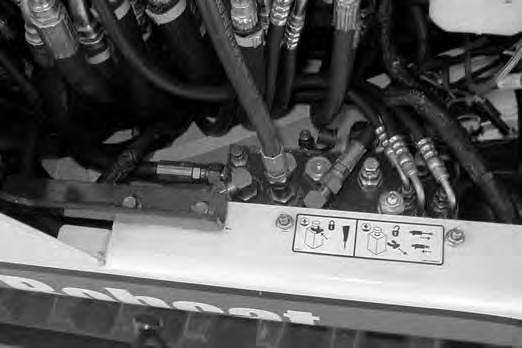
Release the latch (Item 1) [A] and pull the tailgate open. Push firmly to close the tailgate.
The tailgate latch can be locked (Item 2) [A]. Use the excavator key to unlock.
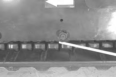
Adjusting The Bumper
The door bumper (Item 1)[B] can be adjusted for alignment with the tailgate.
Close the tailgate before operating the excavator.
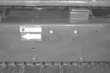
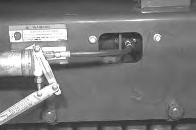
Adjusting The Tailgate Latch
The door catch (Item 1) [C] can be adjusted by loosening the bolt and moving the cylinder the tighten the nut.


Close the tailgate before operating the excavator.
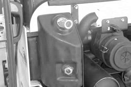
AIR CLEANER
See the SERVICE SCHEDULE Page 35 for the correct service interval.
Daily Check
Check the condition indicator (Item 1) [C]. If the red ring shows in the condition indicator, the filter element needs to be replaced.
Replace the inner filter every third time the outer filter is replaced or as indicated on Page 35.
Replacing The Filters
Outer Filter
Release the two fasteners (Item 2) [C].
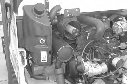
Remove and clean the dust cup (Item 3) [C].
Later Models
Early Models
AIR CLEANER SERVICE (Cont’d)

Outer Filter (Cont’d)
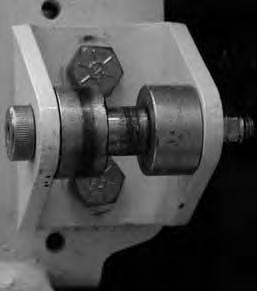
Pull the outer filter from the air cleaner housing [A]
Check the housing for damage.
Clean the housing and the seal surface. Do Not use compressed air.
Install a new element.
Install the dust cup (Item 1) [B] and engage the fasteners (Item 2) [B].
Check the air intake hose and the air cleaner housing for damage. Make sure all connections are tight.
Inner Filter
Only replace the inner filter element under the following conditions:
• Replace the inner filter element every third time the outer filter is replaced.
• After the outer element has been replaced, press the button (Item 3) [B] on the top of the condition indicator and start the engine. Run at full RPM, then reduce engine speed and stop the engine. If thered ring shows in the condition indicator, replace the inner filter element. Remove the dust cup, outer filter and inner filter.

NOTE:Make sure all sealing surfaces are free of dirt and debris.
Install the new inner element [C]
Install the outer element and the dust cup [B]
Press the button on the condition indicator (Item 3) [B] to remove the red ring.
HEATER AIR FILTERS (With Cab Option Only)
The heater filters must be cleaned regularly. The filters are located at the left of the operator seat [D]
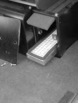
Recirculation Filter
Remove the screws and cover [D]. Remove the filter (Item 1) [D] and wash the filter with a mild detergent and water. Dry the filter before installing.
Fresh Air Filter
Remove the filter (Item 2) [D]. Use low air pressure to clean the filter; or replace when very dirty.
Install the filter, cover and screws.
Fuel System
Fuel Specifications
Use only clean, high quality diesel fuel, Grade No. 2 or Grade No. 1.
The following is a suggested blending guideline which should prevent fuel gelling problems during freezing temperatures:
Temp. F° (C°) No. 2No.1
+15°(9°) 100% 0%
Down to –20° (–29°)50% 50%
Below –20° (–29°) 0% 100%
See your fuel supplier for local recommendations.
Filling The Fuel Tank
Open the side cover and remove the fuel fill cap (Item 1) [A].
Use a clean, approved safety container to addfuel. Add fuel only in an area that has a free movement of air and no flames or sparks. NO SMOKING!
Install and tighten the fuel fill cap. Close the side door.
See the SERVICE SCHEDULE, Page 35 for the service interval when to remove water from or replace the fuel filter.
Always clean up spilled fuel or oil. Keep heat, flames, sparks or lighted tobacco away from fuel and oil. Failure to use care around combustibles can cause explosion or fire which can result in injury or death.
Removing Water From The Fuel Filter
Open the tailgate.
Loosen the drain (Item 1) [B] at the bottom of the filter element to drain water from the filter.
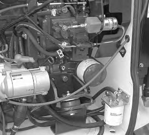
Fuel Filter
See the SERVICE SCHEDULE, Page 35 for the service interval when to remove the water from the fuel filter.
Loosen the drain (Item 1) [B] at the bottom of the filter element to drain water from the filter.
See the SERVICE SCHEDULE, Page 35 for the service interval when to replace the fuel filter.

Remove the filter element (Item 2) [B]
Clean the area around the filter housing. Put oil on the seal of the new filter element.
Install the fuel filter, and hand tighten.
Remove the air from the fuel system. (See Removing Air From the Fuel System , Page 39.)
Stop and cool the engine before adding fuel. NO SMOKING! Failure to obey warnings can cause an explosion or fire.
FUEL SYSTEM (Cont’d)
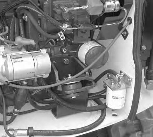
Removing Air From The Fuel System
After replacing the fuel filter or when the fuel tank has run out of fuel, air must be removed from the fuel system before starting the engine.
Open the fuel filter vent (Item 1) [A]
Operate the hand pump (priming bulb) (Item 2)[A] until the fuel flows from the vent with no air bubbles.
Close the vent (Item 1) [A].
Start the engine. It may be necessary to open the vent (Item 3) [A] (at the fuel injection pump) briefly until the engine runs smoothly.
Draining The Fuel Tank
See the SERVICE SCHEDULE, Page 35 for the correct service interval.
Remove the hose (Item 4) [A] from the fuel injection pump. Route the hose to the bottom of the engine compartment and out the tailgate.
Drain the fuel into a container.
Reuse, recycle or dispose of fuel in an environmentallysafe manner.
Diesel fuel or hydraulic fluid under pressure can penetrate skin or eyes, causing serious injury or death. Fluid leaks under pressure may not be visible. Use a piece of cardboard or wood to find leaks. Do not use your bare hand. Wear safety goggles. If fluid enters skin or eyes, get immediate medical attention from a physician familiar with this injury.
W–2072–0496
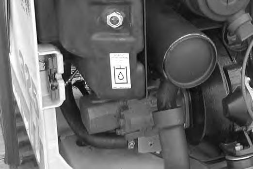
Engine Lubrication System
Checking Engine Oil
Check the engine oil every day before starting the engine for the work shift.
Open the tailgate and remove the dipstick (Item 1) [A] Keep the oil level between the marks on the dipstick.
Use a good quality motor oil that meets the correct API Service Classification. (See FUEL, COOLANT AND LUBRICANTS Chart, Page 80.)
Replacing Oil And Filter
See the SERVICE SCHEDULE, Page 35 for the service interval for replacing the engine oil and filter.
Route the drain hose our the tailgate and run the engine until it is at operating temperature. Stop the engine.
Open the tailgate.
Route the drain hose out the tailgate. Remove the drain cap (Item 2) [A]. Drain the oil into a container.
Recycle or dispose of used oil in an environmentally safe manner.
Remove the oil filter (Item 3)[A] and clean the filter housing surface.
Use a genuine Bobcat replacement filter element.
Put clean oil on the filter gasket. Install the filter and hand tighten.
Install and tighten the oil drain cap.
Remove the fill cap (Item 4) [A].
Put oil in the engine. (See FUEL, COOLANT AND LUBRICANTS Chart, Page 80.)
Install the fill cap.
Start the engine and let it run for several minutes. Stop the engine. Check for leaks at the oil filter. Check the oil level.
Add oil as needed if it is not at the top mark on the dipstick.
Cooling System
Check the cooling system every day to prevent over–heating, loss of performance or engine damage.
Cleaning The Cooling System
Open the tailgate.
Use air pressure or water pressure to clean the radiator and oil cooler [A]. Be careful not to damage fins when cleaning.
Checking Coolant Level
Do not remove radiator cap when the engine is hot. You can be seriously burned.
Open the right side cover.
Check the coolant level in the coolant recovery tank (Item 1) [B].
The coolant level must be between the MIN and MAX marks on the coolant recovery tank when the engine is cold.
NOTE:The cooling system is factory filled with propylene glycol (purple color). DO NOT mix propylene glycol with ethylene glycol.
Avoid Engine Damage
Always use the correct ratio of water to antifreeze.
Too much antifreeze reduces cooling system efficiency and may cause serious premature engine damage.
Too little antifreeze reduces the additives which protect the internal engine components; reduces the boiling point and freeze protection of the system.
Always add a premixed solution. Adding full strength concentrated coolant can cause serious premature engine damage.
• When fluids are under pressure.
• Flying debris or loose material is present.
• Engine is running.
• Tools are being used.
Wear safety glasses to prevent eye injury when any of the following conditions exist: W–2019–1285
COOLING SYSTEM (Cont’d) Replacing The Coolant
See the SERVICE SCHEDULE, Page 35 for the correct service intervals.
Do not remove radiator cap when the engine is hot. You can be seriously burned.
W–2070–1285
When the engine is cool, loosen and remove the radiator cap (Item 1) [A].
Put a hose on the drain valve at the bottom of the radiator. Open the drain valve (Item 1)[B] and drain the coolant into a container.
Put a hose on the drain valve on the engine block. Open the drain valve (Item 1) [C] drain the coolant into a container.
After all the coolant is removed, close both drain valves. Recycle or dispose of the used coolant in an environmentally safe manner.
Mix the coolant in a separate container. (See FUEL, COOLANT AND LUBRICANTS Chart, Page 80, for correct capacity.)
NOTE:The cooling system is factory filled with propylene glycol (purple color). DO NOT mix propylene glycol with ethylene glycol.
Add premixed coolant; 47% water and 53% propylene glycol to the recovery tank if the coolant level is low.
One gallon and one pint of propylene glycol mixed with one gallon of water is the correct mixture of coolant to provide a –34°F (–37°C) freeze protection. (See IMPORTANT, Page 41.)

Use a refractometer to check the condition of propylene glycol in your cooling system.
Add premixed coolant until the level is correct.
Run the engine until it is at operating temperature. Stop the engine. Check the coolant level and add as needed. Be sure the radiator cap is tight.
Add coolant to the recovery tank as needed. Close the tailgate.
ELECTRICAL SYSTEM Description
The excavator has a 12 volt, negative ground electrical system. The electrical system is protected by fuses located under the cover at the right side of the excavator (Item 1) [A]. The fuses will protect the electrical system whenthere is an electrical overload. The reason for the overload must be found before starting the engine again.
The battery cables must be clean and tight. Check the electrolyte level in the battery. Add distilled water as needed. Remove acid or corrosion from the battery and cables with a sodium bicarbonate and water solution.
Put Battery Saver P/N 6664458 or grease on the battery terminals and cable ends to prevent corrosion.
Batteries contain acid which burns eyes and skin on contact. Wear goggles, protective clothing and rubber gloves to keep acid off body.
In case of acid contact, wash immediately with water. In case of eye contact get prompt medical attention and wash eye with clean, cool water for at least 15 minutes.
If electrolyte is taken internally drink large quantities of water or milk! DO NOT induce vomiting. Get prompt medical attention.
W–2065–1296
Fuse
A decal is inside the cover to show location and amp ratings.
Remove the cover to check or replace the fuses. The location and sizes are shown below and [B]
Always replace fuses using the same type and capacity.
ELECTRICAL SYSTEM (Cont’d)
Removing And Installing The Battery
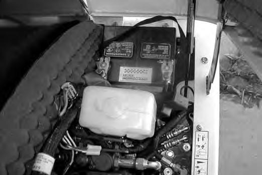
Open the right side cover.
Disconnect the negative (–) cable (Item 1) [A] first.
Disconnect the positive (+) cable (Item 2) [A]
Remove the bolts (Item 3) [A] and remove the hold down clamp.
Remove the battery.
Always clean the terminals and the cable ends, even when installing a new battery.
Install the battery. Install the hold down clamp and tighten the bolts.
Connect the battery cables. Connect the negative (–)cable (Item 1) [A] last to prevent sparks.
Batteries contain acid which burns eyes and skin on contact. Wear goggles, protective clothing and rubber gloves to keep acid off body.
In case of acid contact, wash immediately with water. In case of eye contact get prompt medical attention and wash eye with clean, cool water for at least 15 minutes.
If electrolyte is taken internally drink large quantities of water or milk! DO NOT induce vomiting. Get prompt medical attention.
W–2065–1296
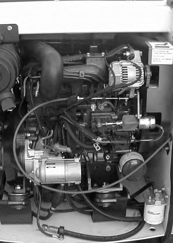
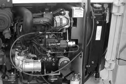
Alternator
Adjusting The Alternator Belt
Stop the engine. Open the tailgate.
Loosen the alternator mounting bolts (Item 1) [B].
Move the alternator until the belt has 1/2 inch (13 mm) movement at the middle of the belt span (Item 1) [C] with 13 lbs (58 N) of force.
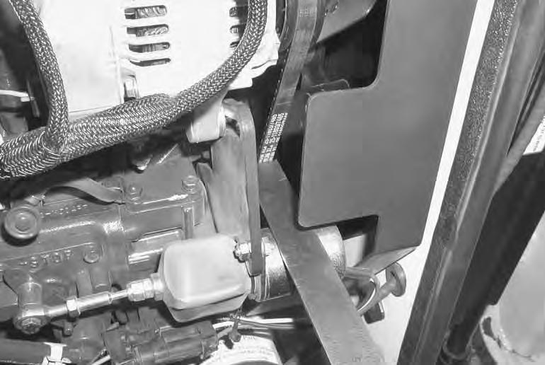

Tighten the mounting bolts.
Replace the belt if it has stretched or there are cracks inthe belt. Replace the pulley if the belt contacts the bottom of the groove in the pulley.
Close the tailgate.
ELECTRICAL SYSTEM (Cont’d)
Removing And Installing The Battery
Open the tailgate.
Disconnect the negative (–) cable (Item 1) [A] first.
Disconnect the positive (+) cable (Item 2) [A]
Remove the bolts (Item 3) [A] and remove the hold down clamp.
Remove the battery.
Always clean the terminals and the cable ends, even when installing a new battery.
Install the battery. Install the hold down clamp and tighten the bolts.
Connect the battery cables. Connect the negative (–)cable (Item 1) [A] last to prevent sparks.
Batteries contain acid which burns eyes and skin on contact. Wear goggles, protective clothing and rubber gloves to keep acid off body.
In case of acid contact, wash immediately with water. In case of eye contact get prompt medical attention and wash eye with clean, cool water for at least 15 minutes.
If electrolyte is taken internally drink large quantities of water or milk! DO NOT induce vomiting. Get prompt medical attention.
W–2065–1296
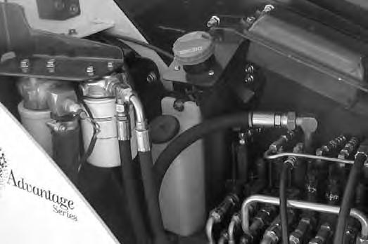
HYDRAULIC SYSTEM Checking And Adding Fluid
Put the machine on a flat level surface. Retract the arm and bucket cylinders, put the bucket on the ground and raise the blade. Stop the engine. Open the tailgate.
Check the hydraulic fluid level, it must be visible in the sight gauge (Item 1) [A]
Clean the surface around the reservoir (breather) cap and remove the cap from the reservoir (Item 2) [A].
Check the condition of the fill strainer screen (Item 1) [B] Clean or replace as necessary.
Be sure the screen is installed before adding oil. Add the correct fluid to the reservoir until it is visible in the sight gauge. (See FUEL, COOLANT AND LUBRICANTS Chart, Page 80.)
Check the breather cap and clean as necessary. Replace the cap if damaged.
Install the reservoir cap. Close the tailgate.
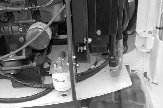
HYDRAULIC SYSTEM (Cont’d)
Replacing The Hydraulic Oil
See the SERVICE SCHEDULE, Page 35 for the correct service interval.
Retract the arm and bucket cylinders, lower the bucket to the ground. Stop the engine.
Open the tailgate.
Remove the drain plug (Item 1) [A]
Drain the fluid into a container.
Recycle or dispose of the fluid in an environmentally safe manner.
Install the drain plug (Item 1) [A]
Add fluid to the reservoir. (See FUEL, COOLANT AND LUBRICANTS Chart, Page 80.)
Open the bleed valve (Item 1) [B] on the hydraulic pump. Close the valve after a steady stream ofhydraulic fluid free of any air bubbles drains from the valve. Tighten the bleed valve. DO NOT RUN THE MACHINE WITH THE BLEED VALVE OPEN.

Start the engine and operate the machine through the hydraulic functions. Stop the engine. Check the fluid level and add as needed.
Diesel fuel or hydraulic fluid under pressure can penetrate skin or eyes, causing serious injury or death. Fluid leaks under pressure may not be visible. Use a piece of cardboard or wood to find leaks. Do not use your bare hand. Wear safety goggles. If fluid enters skin or eyes, get immediate medical attention from a physician familiar with this injury.
Always clean up spilled fuel or oil. Keep heat, flames, sparks or lighted tobacco away from fuel and oil. Failure to use care around combustibles can cause explosion or fire which can result in injury or death.
W–2103–1285
HYDRAULIC SYSTEM (Cont’d)
Replacing the Hydraulic Filter
See the SERVICE SCHEDULE, Page 35 for the correct service interval.

Pull the latch (Item 1) [A] and open the right side cover. Tilt the cover forward until the stop engages.
Remove the filter element (Item 1) [B]
Clean the housing where the filter gasket makes contact.
Put clean hydraulic fluid on the gasket. Install the new filter element and hand tighten only.
Replacing the Case Drain Filter
Open the right side cover [A].
Remove the filter element (Item 2) [B]
Clean the housing where the filter gasket makes contact. Put clean hydraulic fluid on the gasket. Install the new filter element and hand tighten only.
HYDRAULIC SYSTEM (Cont’d)
Diagnostic Couplers
Open the right side cover [A]
Diagnostic couplers (Item 1) [B] & [C] are located on the hydraulic circuitry.

The diagnostic coupler (Item 2) [B] is used in the factory during production only.
The coupler (Item 1) [C] can be used to check circuit pressures. (Refer to the Service Manual.)
SPARK ARRESTOR MUFFLER (If Equipped)
See the SERVICE SCHEDULE, Page 35 for the correct service interval.
Do not operate the excavator with a defective exhaust system.
This excavator is factory equipped with a U.S.D.A. Forestry Service approved spark arrestor muffler. It is necessary to do maintenance on this spark arrestor muffler to keep it in working condition. The spark arrestor muffler must be serviced by dumping the spark chamber every 100 hours of operation.
If this machine is operated on flammable forest, brush or grass covered land, it must be equipped with a spark arrestor attached to the exhaust system and maintained in working order. Failure to do so will be in violation of California State Law, Section 4442 PRC.
Make reference to local laws and regulations for spark arrestor requirements.
I–2061–0195
This excavator is factory equipped with a U.S.D.A. Forestry Service approved spark arrestor muffler. It is necessary to do maintenance on this spark arrestor muffler to keep it in working condition. The spark arrestor muffler must be serviced by dumping the spark chamber every 100 hours of operation.
When the engine is running during service, the steering levers must be in neutral.
Failure to do so can cause injury or death.
W–2203–0595
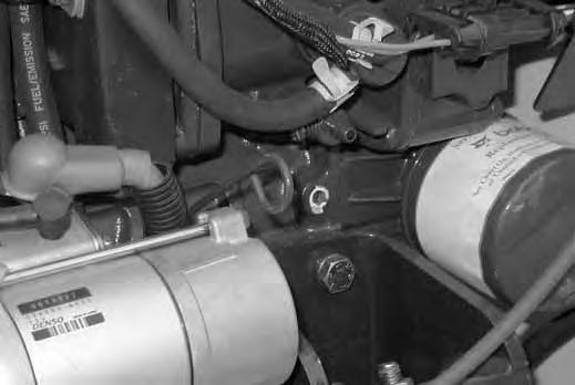
Stop the engine. Open the tailgate.
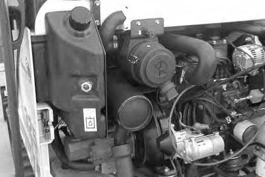
Remove the plug (Item 1) [A] from the bottom of the muffler.
Start the engine and run for about 10 seconds while a second person, wearing safety glasses, holds a piece of wood over the outlet of the muffler. The carbon deposits will be forced out of the muffler plug hole (Item 1) [A]
Stop the engine. Install and tighten the plug. Close the tailgate.
If this machine is operated on flammable forest, brush or grass covered land, it must be equipped with a spark arrestor attached to the exhaust system and maintained in working order. Failure to do so will be in violation of California State Law, Section 4442 PRC.
Make reference to local laws and regulations for spark arrestor requirements.
I–2061–0195
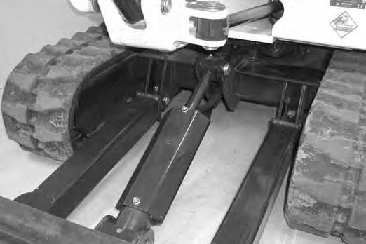
Track Tension
NOTE:The wear of the pins and bushings on the undercarriage vary with the working conditions and the different types of soil conditions. It is necessary to inspect track tension and maintain the correct tension. See Service Schedule, Page 35 for the correct service interval.
Raise one side of the machine (Approximately fourinches) using the boom and arm [A].
Raise the blade fully and install jackstands under theblade and track frame (Item 1) [A]. Lower the boom until all machine weight is on the jackstands. Stop the engine.

Avoid Injury
Keep fingers and hands out of pinch points when checking the track tension.
W–2142–0189
Rubber Track Clearance
Measure the sag at the middle track roller [B]. Do Not get fingers into pinch points between the track and the track roller. Use a bolt or a dowel of the appropriate size to check the gap between the contact edge of the roller and the top edge of the track guide lug [B] & [C]
Rubber Track Clearance
0.562 inch (15,0 mm)
Track Sag 9/16 inch (15 mm)
TRACK TENSION (Cont’d)
Steel Track Clearance
Measure the steel track sag at the center of the track, between the contact surface of the roller and the contact surface of the track [A]. Do Not get fingers into pinchpoints between the track and the track roller.
Steel Track Clearance
4.25–4.75 inches (108–120 mm)
Adjustment
Loosen the two bolts from the cover (Item 1) [B]. Pivot the cover downward.

4.25–4.75 inches (108–120 mm)
Add grease to the fitting (Item 1) [C] until the track tension is correct.
Use tool MEL –1560 (Item 1) [D] to loosen the bleed fitting (Item 2) [D] to release tension from the track.
NOTE:Do not loosen the grease fitting (Item 3) [D].
Repeat the procedure for the other side.
Travel Motor
Checking Oil Level
Put the machine on a level surface with the plugs positioned as shown (Item 1 & 2) [A].
Remove the plug (Item 1) [A]. The oil level should be at the bottom edge of the plug hole.
Add gear lube through the hole (Item 2) [A] until oil just begins to flow from the hole (Item 1) [A]. (See FUEL, COOLANT AND LUBRICANT Chart, Page 80 for the capacity and type.)

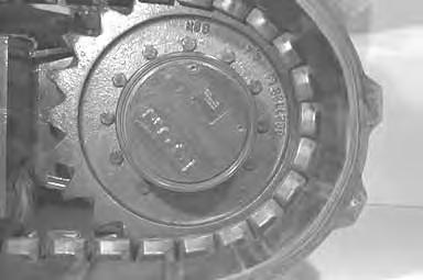
Install the plugs.
Repeat the procedure for the other side.
Draining Final Drive Case
See the SERVICE SCHEDULE, Page 35 for the correct service interval.
Put the machine on a level surface with the plugs positioned as shown (Item 1 & 2) [B].
Remove both plugs (Items 1 & 2) [B] and drain into a container. Recycle or dispose of the fluid in an environmentally safe manner.
After all the gear lube is removed, install plug (Item 1) [B]
Add gear lube to the plug hole (Item 2) [B] until the gear lube level is at the bottom edge of the plug hole (Item 2) [B] Install and tighten the plugs.
Repeat the procedure for the other side.
LUBRICATION OF THE HYDRAULIC EXCAVATOR
Lubricate the Hydraulic Excavator as specified in the SERVICE SCHEDULE, Page 35 for the bestperformance of the machine.

Always use a good quality lithium based multipurpose grease when lubricating the machine. Apply the lubricant until extra grease shows.
Lubricate the following locations on the Hydraulic Excavator EVERY 8–10 HOURS:

Ref. Description (# of Fittings)
1.Blade Cylinder Rod End (1) [A]
2.Blade Cylinder Base End (1) [A].
3.Blade Pivots (2) [A].
4.Boom Swing Cylinder Rod End (1) [A]
5.*Swing Circle Pinion (1) [A].
6.*Swing Circle Bearing (1) [A].
7.Boom Swing Cylinder Base End (1) [A].
8.Boom Swing Pin (1) [B]
9.Boom Swing Pivot (3) [B]
10.Boom / Swing Frame Pivot (1) [B]
11.Boom Cylinder Base End (1) [C].
12.Boom Cylinder Rod End (1) [C]
13.Arm Cylinder Base End (1) [C]
14.Arm Cylinder Rod End (1) [D].

15.Arm / Boom Pivot (1) [D]
16.Bucket Cylinder Base End (1) [D].
* Lubricate every 50 hours. Use 4 to 5 pumps from a grease gun, rotate the upperstructure 180 ° and add another 4 to 5 pumps of grease.
LUBRICATION OF THE HYDRAULIC EXCAVATOR (Cont’d)
Ref.Description (# of Fittings)
17.Bucket Cylinder Rod End (1) [A].

18.Bucket Link Pins (1) [A]
19.Bucket / Arm Pivot (1) [A].
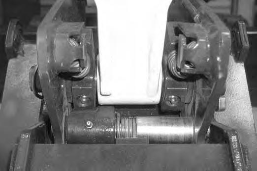
20.X–Change Latch (1) [B]
21.X–Change Pivot Pin (2) [B].

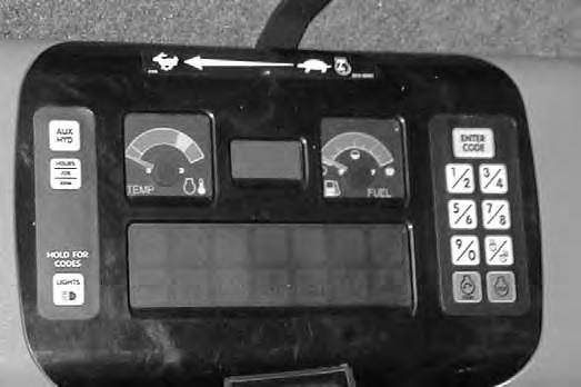
Service Codes
The LCD (Liquid Crystal Display) on the Right Instrument Panel can change from engine hours to SERVICE CODES (See at right.). These CODES help your dealership analyze monitored functions of your Bobcat excavator. Some service procedures must be performed ONLY BY QUALIFIED BOBCAT SERVICE PERSONNEL.
The Prefix, in the left two columns, followed by a Suffix, in the right two columns, will indicate a Function Error.
EXAMPLE: 02–17
Prefixfunction
02Hydraulic Charge Filter
03Battery Voltage
04Engine Oil Pressure
05Hydraulic Charge Pressure
06Engine Speed
07Hydraulic Oil Temperature
08Engine Coolant Temperature
09Fuel Level
Press and hold LIGHTS Button (Item 10) [A] (Page 4) for three seconds to view SERVICE CODES in the LCD (Item 12) [A] (Page 4). If more than one SERVICE CODE is present, the codes will scroll on the LCD
Service Codes
Suffixerror Description
02Error ON (Detects ON when should be OFF)
03Error OFF (Detects OFF when should be ON)
04In Error
05Short To Battery (Detects 12V & should not be)
06Short To Ground
07Open Circuit (Not grounded)
09Low
10High
12Front Auxiliary PWM Switch (Proportional Control)
13Fuel Shutoff Solenoid – Secondary
14Fuel Shutoff Solenoid – Primary
20Two Speed
21Glow Plugs
22Starter Output
26Solenoid for Front Female Coupler
27Solenoid for Front Male Coupler
28Diverter Valve Solenoid
31Recovery Mode Failure (Loss of Power)
33Constant Data (Stored Machine Information)
36 Attachment Control Device (ACD) Controller
60Secondary Thumb Switch
62Load Moment Monitoring
63Workgroup / Travel Console Sensor
64Accessory Relay
65Workgroup / Travel Lockout Solenoid
80ACD Output A
82ACD Output C
83ACD Output D
84ACD Output E
85ACD Output F
86ACD Output G
87ACD Output H
11Extremely High
14Extremely Low
15In Shutdown
16Not Connected
17Plugged
18Out Of Range
21Out Of Range High
(Above detectable range of sensor)
22Out Of Range Low
(Below detectable range of sensor)
23Not Calibrated
28Failure
Multiple SERVICE CODES and / or Abnormal Symptoms can be caused by corroded or loose ground connection. Flashing instrument panel lights, alarm beeping, front & rear lights flashing, low battery voltage, loose battery connectors, could also indicate a poor ground. Check all grounds before performing other diagnostics.
Deluxe Instrument Panel Setup
Passwords
All new machines with Deluxe Instrumentation arrive at Bobcat Dealerships with the panel in locked mode. This means that a password must be used to start the engine. For security purposes, your dealer may change the password and also set it in the locked mode. Your dealer will provide you with the password.
• Master Password:
A permanent, randomly selected password set at the factory which cannot be changed. This password isused for service by the Bobcat dealer if the Owner Password is not known; or to change the Owner Password.
Owner Password: There is only one Owner Password ( CodE 0). It must be used to change the owner or operator passwords. See below for changing the Owner Password.
Operator Password:
There can be up to three Operator Passwords ( CodE 1, CodE 2, or CodE 3). See below for changing the Operator Password.
Changing The Operator Password
Perform Password Entry at left using the owner password, but do not start the engine.
Press and hold the ENTER CODE Button (Item 1) [A] for three seconds. CodE 0 will appear on the LCD (Item 2)[A]
Password
Entry (For Starting and Operating the Machine)
Press ENTER CODE Button (Item 1) [A]. The panel will become lighted and there will be two short beeps.CodE will appear on the LCD (Item 2) [A]
NOTE: After you press ENTER CODE you have 40 seconds to use the keypad (Item 3)[A] to enter the password. (If more than 40 seconds is used, the process will abort and you will need to start over.)
Enter the password. For each digit that you enter, a dash will appear on the LCD. If the password was entered correctly, there will be one long beep.
NOTE: If the password was incorrect there will be three short beeps and Error will appear on the LCD. Press the ENTER CODE Button again and start over. After three failed attempts, you must wait three minutes to try again.
You are now ready to start and operate the machine.
If you will be changing passwords, do not start the engine. (See Changing The Password at right.)
Press the ENTER CODE Button until the desiredOperator Code ( CodE 0, CodE 1, CodE 2, CodE 3) appears. CodE 0 is Owner Password, the other codes are Operator Passwords. You now have 40 seconds to use the keypad (Item 3) [A] to enter each digit of a new four digit password.
Enter the new four digit password. After the fourth digit is entered, there will be two short beeps and rPEAt will appear.
Re–enter the new four digit password to verify. If the new passwords match, there will be two short beeps, CodE will appear for 1 second and then the LCD will return to HOURMETER function.
NOTE: If the new passwords do not match, there will be one long beep and Error will appear for 1 second and then the LCD will return to HOURMETER function.
DELUXE INSTRUMENT PANEL SETUP (Cont’d)
Password Lockout Feature
This allows the operator to Unlock the password feature so that a password does not need to be used every time you start the engine.
Perform Password Entry (Page 60). (The engine can be started or stopped.)
Press the Lock/Unlock Button (Item 1) [A]. The LCD will continuously alternate from UnLoc to CodE for 1 second periods.
Perform Password Entry again.
UnLoc will appear in the LCD (Item 5) [A], the Unlocked Icon (Item 2) [A] will appear in the Icon Display Area (Item 3) [A] and there will be two short beeps.
To start an Unlocked system, press the ENTER CODE Button and press the START Button.
When you stop the engine with the system unlocked, you will hear one long beep every 3 seconds for 15 seconds.
To lock the system again, press the Lock/Unlock Button (Item 1) [A] and enter the password during the 15 second period.
Job Clock
The JOB CLOCK can be set to record accumulated hours for a particular job.
Press and release the HOURS/JOB/RPM Button (Item 4) [A] until JOB light is ON at the top, center of the LCD (Item 5) [A].
While the JOB light is ON, press and hold the HOURS/JOB/RPM Button (Item 4) [A] until the LCD retruns to zero.
This process will clear the accumulated hours and will begin recording JOB CLOCK time again. (This does not affect the HOURMETER which continues to record the total operating hours of the excavator.)
Pressing the HOURS/JOB/RPM Button again or pressing the START Button will return the LCD to HOURMETER function.
Rpm
The LCD (Item 5) [A] can be set to display engine RPM.
With the engine running, press and release the HOURS/JOB/RPM Button (Item 4) [A] until RPM light is ON at the top, left of the LCD (Item 5) [A].
Engine RPM is now displayed in the LCD.
Press the HOURS/JOB/RPM Button (Item 4) [A] again the return to HOURMETER function.
Machine Sign Translations
6804114, 6804232 & 6804233)
6808474)
ADVERTENCIA (SPANISH)
Los procedimientos de carga, transporte e izado inadecuados pueden provocar lesiones graves o la muerte.
TRANSPORTE DE LA UNIDAD
• Use rampas metálicas de carga con entablado y superficies antideslizantes.
• Fije las rampas a la plataforma de apoyo del camión.
• Aplique el freno de estacionamiento del camión y bloquee los neumáticos del camión.
• El ángulo de la rampa no debe exceder los 15° .
• El tope de la rampa debe estar a nivel con la cama del camión.
• Empalme el bloqueo del giro.
• Amarre la unidad con cadenas de sujeción y bloquee las orugas.
PARA IZAR LA UNIDAD
• El dispositivo de izado debe tener capacidad adecuada para el peso de la unidad.
• Mantenga el centro de gravedad y el equilibrio al izar.
• No haga girar el pescante o el armazón superior. Aplique el bloqueo del giro.
• Nunca ize cuando el operador está en l a unidad.
AVERTISSEMENT (FRENCH)
Des procédures de chargement, transport et levage incorrectes risquent de provoquer des blessures graves ou la mort. TRANSPORT DE LA MACHINE
• Utilisez une rampe de chargement métallique à surface antidérapante, munie de bordures latérales.
• Fixez la rampe à la plate-forme du camion.
• Serrez le frein de stationnement du camion et calez ses roues.
• L’angle de la rampe ne doit pas dépasser 15°
• Le haut de la rampe doit être au niveau de la plate-forme du camion.
• Engagez le verrou de pivotement.
• Arrimez la machine avec des chaînes et calez les chenilles.
LEVAGE DE LA MACHINE
• Le dispositif de levage doit avoir la capacité suffisante pour le poids de la machine.
• Veillez à conserver le centre de gravité et l’équilibre lors du levage.
• Ne faites pas pivoter la flèche ni le châssis supérieur. Engagez le verrou de pivotement.
• Ne levez jamais la machine lorsque l’opérateur s’y trouve.
Translation not available.
Translation not available.
ADVERTENCIA (SPANISH)
LA GRASA A PRESIÓN ALTA PUEDE CAUSAR LESIONES SERIAS
• No afloje la grasera.
• No afloje el drenaje de la grasera más de 1-1/2 vueltas
AVERTISSEMENT (FRENCH)
GRAISSE SOUS FORTE PRESSION. RISQUE DE BLESSURES GRAVES
• Ne desserrez pas le graisseur.
• Ne desserrez pas le raccord de purge de plus d’un tour et demi.
ADVERTENCIA (SPANISH)
Las superficies calientes pueden causar lesiones serias. No toque.
Permita que se enfríe antes de realizar tareas de mantenimiento.
AVERTISSEMENT (FRENCH)
Risque de brûlures graves sur les surfaces brûlantes. Ne touchez pas.
ADVERTENCIA (SPANISH)
EL CILINDRO CONTIENE GAS BAJO ALTA PRESION. EL ABNRIR EL CILINDRO PUEDE SOLTAR LA VARILLA Y CAUSAR HERIDAS O LA MUERTE.
AVERTISSEMENT (FRENCH)
LES VERINS RENFERMENT UN GAZ SOUS PRESSION. NE JAMAIS OUVRIR UN VERIN CAR LA TIGE RISQUE DE S’ECHAPPER BRUTALEMENT ET DE CAUSER DES BLESSURES OU MEME LA MORT.
Laissez refroidir avant l’entretien.
ADVERTENCIA (SPANISH)
• Fluido presurizado caliente.
• Puede provocar quemaduras graves.
AVERTISSEMENT (FRENCH)
• Fluide brûlant sous pression.
• Risque de brûlures graves.
ADVERTENCIA (SPANISH)
EVITE LESIONES O MUERTE
• Conozca el esquema de control antes de operar la unidad.
• Para mayor información vea el Manual de operación y mantenimiento.
AVERTISSEMENT (FRENCH)
ÉVITEZ LES BLESSURES OU LA MORT
• Avant de vous servir de la machine, assurez–vous de bien connaître la séquence de commandes à suivre.
• Voir le Manuel de l’opérateur et d’entretien ou le Guide de l’opérateur pour plus de renseignements.
325 Excavator Specifications
• All dimensions are shown in inches. Respective metric dimensions (mm) are enclosed by parentheses.
• Where applicable, specifications conform to SAE or ISO standards and are subject to change without notice.
Performance Specifications:
Operating Weightw/ Canopy 6145 lbs. (2788 kg) . . . . . . . . (w/ 24 inch Bucket)w/ Cab 6408 lbs. (2907 kg)
Travel Speed Low 1.2 MPH (1,9 km/hr) . . . . . . . . . . . High 1.9 MPH (3,1 km/hr)
Engine:
Make/Model KUBOTA D1703–B–BOBCAT–I–SI . . . . . . . . . . . .
Fuel/Cooling Diesel / Liquid (Antifreeze mixture)
Horsepower (SAE Net)27.5 HP (20,5 kW) @ 2200 RPM
Number of CylindersThree
Lubrication Pressure System W/Filter
Air Cleaner Dry replaceable cartridge, dual . . . . . . . . . . . . . element
Controls:
Steering Two hand levers or foot pedals . . . . . . . . . . . . . . .
Hydraulics Two hand operated levers (joysticks) control boom, bucket, arm and cab swing
Auxiliary HydraulicsElectric switches in joysticks
Brakes Travel Service & ParkingHydraulic lock on motor Swing Spring applied, hyd.released Service Hydraulic lock on motor
Drive System: Final Drive
Each track is independently driven by an Axial Piston Motor
Type of Reduction Two–stage planetary gear reduction
Hydraulic System :
*Boom, Arm, Bucket, Blade, Auxiliary Hydraulics
Electrical System:
Alternator 12–Volt, 40 amp, open, negative ground
Battery 12 Volt – 500 CCA @ 0°F (–18°C)
Instrumentation –Hourmeter, temperature and fuel gauges, audible alarm, and visual warning for engine functions. Optional Keyless start.
Fluid Capacities and Type – See FUEL COOANT AND LUBRICANTS Page 80.
328 (and 325 with Long Arm Kit) EXCAVATOR SPECIFICATIONS
• All dimensions are shown in inches. Respective metric dimensions (mm) are enclosed by parentheses.
• Where applicable, specifications conform to SAE or ISO standards and are subject to change without notice.
Fuel/Cooling Diesel / Liquid (Antifreeze mixture)
Horsepower (SAE Net)27.5 HP (20,5 kW) @ 2200 RPM
Number of CylindersThree
Lubrication Pressure System W/Filter Air Cleaner Dry replaceable cartridge, dual
Controls:
Steering Two hand levers or foot pedals .
Hydraulics
Two hand operated levers (joysticks) control boom, bucket, arm and cab swing
Auxiliary HydraulicsElectric switches in joysticks
Brakes
Travel
Service & ParkingHydraulic lock on motor Swing Spring applied, hyd.released Service Hydraulic lock on motor
Drive System: Final Drive
Each track is independently driven by an Axial Piston Motor Type of Reduction Two–stage planetary gear reduction
Hydraulic System : Variable Displacement to 10.46 GPM (39.6 L/m) Gear Pump
Auxiliary Flow 12.26 GPM (46,4 L/m)
System Relief Setting
Implement* Circuit2500 PSI (172,4 BAR)
Travel Circuit 3500 PSI (241,3 BAR)
Swing Circuit 1700 PSI (117,2 BAR)
*Boom, Arm, Bucket, Blade, Auxiliary Hydraulics
Electrical System: Alternator 12–Volt, 40 amp, open, negative ground
Battery 12 Volt – 500 CCA @ 0°F (–18°C)
Instrumentation –Hourmeter, temperature and fuel gauges, audible alarm, and visual warning for engine functions. Optional Keyless start.
Fluid Capacities and Type – See FUEL COOANT AND LUBRICANTS Page 80.
Excavator Specifications
325 Lifting Capacity
FUEL, COOLANT AND LUBRICANTS
Chart
Fuel, Coolant and Lubricants
Reservoirtype Of Fluid Recommended Fluids
RECOMMENDED SAE VISCOSITY NUMBER (LUBRICATION OILS FOR DIESEL ENGINE CRANKCASE)
SAE 40W or 20W–50
–40
SAE 10W–30
SAE 15W–40
SAE 30W
* SAE 5W–30
SAE 20W–20
SAE 10W
SYNTHETIC OIL Use recommendation from Synthetic Oil Mfgr.
TEMPERATURE RANGE ANTICIPATED BEFORE NEXT OIL CHANGE (DIESEL ENGINES MUST USE API CLASSIFICATION CD, CF4, CG4 ) premixed coolant; 47% water and 53% propylene
* Can be used ONLY when available with appropriate diesel rating.
Glycol glycol to the recovery tank if the coolant level is low. One(5,7 gallon and one pint of propylene glycol mixed with one gallon of water is the correct mixture of coolant to provide a –34°F (–37°C) freeze protection. Check condition with a refractometer.
Hydraulic Bobcat FluidIf Bobcat fluid is not available, use engine oil
6563328*SAE 10W–30 or 10W–40, Class SE, or better.
– 90W
* Engine Oil Change Interval Relating to Diesel Fuel Sulfur Content
Sulfur ContentChange Interval
0.5 % or LessChange engine oil and filter as shown on the SERVICE SCHEDULE Page 35.
0.5– 1.0 %Use 1/2 of Service Schedule interval.
Above 1.0 %Use 1/4 of Service Schedule interval.
BOBCAT APPROVED ATTACHMENTS & ACCESSORIES
These and other attachments are approved for use on this model Bobcat excavator. Do not use unapproved attachments. Attachments not manufactured by Bobcat may not be approved.
The versatile Bobcat excavator quickly turns into a multi–job machine with a variety of attachments.
See your Bobcat dealer for more details on the these and other attachments and field accessories. Increase the versatility of your Bobcat Excavator with a variety of bucket sizes.
Buckets Available
Many different bucket widths/capacities are available for a variety of applications. See your Bobcat dealer for the correct bucket for your application.
Trenching
Attachments
Dig 6” – 36” holes with ease and accuracy. Break up concrete quickly and easily.
Use with a bucket to pick up debris. Requires the use of port relief valves in the auxiliary valve circuit.
Must be used with X–Change™ system. Use with the hydraulic clamp to pick up debris, rocks, etc.
Must be used with the X–Change™ system. Use for compacting soil after the excavating job is finished.
Must be used with the X–Change™ system. Used for rotating the bucket to cut at angles and for finishing work.
Must be used with the X–Change™ system. Used for penetrating and to scarify frost or hard ground.
–gives basic operation instruction and safety warnings.

Parts
ADDITIONAL PUBLICATIONS and TRAINING MATERIALS
The following publications and training materials are also available for your Bobcat Compact Excavator. You can order them from your Bobcat dealer.
For the latest information on Bobcat products and the Bobcat / Ingersoll–Rand, visit our website at www.bobcat.com
–Up–to–date PARTS information is also available. See your BOBCAT dealer.
–complete maintenance and overhaul instructions for your Bobcat Excavator. –complete instruction on the correct operation and the routine maintenance of the Bobcat Excavator.
–Introduces operator to step–by–step basics of Compact Excavator operation.
–provides basic safety procedures and warnings for your Bobcat
–provides basic safety instructions.