27 minute read
BEFORE OPERATING THE BOBCAT COMPACT EXCAVATOR


Safety Alert Symbol
This symbol with a warning statement, means: “Warning, be alert! Your safety is involved!” Carefully read the message that follows.
The Bobcat excavator and attachment must be in good operating condition before use. Check all of the items on the Bobcat Service Schedule Decal under the 8–10 hour column or as shown in this Manual.
SAFE OPERATION NEEDS A QUALIFIED OPERATOR *
A QUALIFIED OPERATOR MUST DO THE FOLLOWING:
• UNDERSTAND THE WRITTEN INSTRUCTIONS, RULES AND REGULATIONS
• The written instructions from Bobcat Company include the Delivery Report, Operation & Maintenance Manual, Operator’s Handbook, Safety Manual and machine signs (decals).
• Check the rules and regulations at your location. The rules may include an employer’s work safety requirements. Regulations may apply to local driving requirements or use of a Slow MovingVehicle (SMV) emblem. Regulations may identify a hazard such as a utility line.
• HAVE TRAINING WITH ACTUAL OPERATION
Operator must have instructions before operating the machine. Untrained operators can cause injury or death.
W–2001–0502
Warnings on the machine and in the manuals are for your safety. Failure to obey warnings can cause injury or death.
W–2044–1285
• Operator training must consist of a demonstration and verbal instruction. This training is given by your Bobcat dealer before the product is delivered.
• The new operator must start in an area without bystanders anduse all the controls until he can operate the machine and attachment safely under all conditions of the work area. Always fasten seat belt before operating.
• Operator Training Courses are available from your Bobcat dealer in English and Spanish. They provide information for safe and efficient equipment operation. Safety videos are also available.
• Service Safety Training Courses are available from your Bobcat dealer. They provide information for safe and correct service procedures.
• KNOW THE WORK CONDITIONS
• Know the weight of the materials being handled. Avoid exceeding the Rated Lift Capacity of the machine. Material which is very dense will be heavier than the same volume of less dense material. Reduce the size of load if handling dense material.
• The operator must know any prohibited uses or work areas, for example, he needs to know about excessive slopes.
• Know the location of any underground lines. Call local utilities or the TOLL FREE phone number found in the SAFETY INSTRUCTIONS Section of this manual.
• Wear tight fitting clothing. Always wear safety glasses when doing maintenance or service. Safety glasses, hearing protection or special applications kit are required for some work.See your dealer about Bobcat Safety equipment.
* For an operator be qualified, he must not use drugs or alcoholic drinks which impair his alertness or coordination while working. An operator who is taking prescription drugs must get medical advice to determine if he can safely operate a machine.
SI23–0502
Fire Prevention
The machines and some attachments have components that are at high temperatures under normal operating conditions. The primary source of high temperatures is the engine and exhaust system. The electrical system, if damaged or incorrectly maintained, can be a source of arcs or sparks.
Flammable debris (leaves, straw, etc.) must be removed regularly. If flammable debris is allowed to accumulate, it can cause a fire hazard. Clean often to avoid this accumulation. Flammable debris in the engine compartment is a potential fire hazard.
The spark arrestor exhaust system (if equipped) is designed to control the emission of hot particles from the engine and exhaust system, but the muffler and the exhaust gases are still hot.
• Do not use the machine where exhaust, arcs, sparks or hot components can contact flammable material, explosive dust or gases.
• The operator cab, engine compartment and engine cooling system must be inspected every day and cleaned if necessary to prevent fire hazards and overheating.
• Check all electrical wiring and connections for damage. Keep the battery terminals clean andtight. Repair or replace any damaged part.
• Check fuel and hydraulic tubes, hoses and fittings for damage and leakage. Never use open flame or bare skin to check for leaks. Tighten or replace any parts that show leakage. Always clean fluid spills. Do not use gasoline or diesel fuel for cleaning parts. Use commercial nonflammable solvents.
• Do not use ether or starting fluids on any engine which has glow plugs. These starting aids can cause explosion and injure you or bystanders.
• Always clean the machine, disconnect the battery, and disconnect the wiring from the electronic controllers before welding. Cover rubber hoses, battery and all other flammable parts. Keep a fire extinguisher near the machine when welding. Have good ventilation when grinding or welding painted parts. Wear dust mask when grinding painted parts. Toxic dust or gas can be produced.
• Stop the engine and let it cool before adding fuel. No smoking!
• Use the procedure in the Operation & Maintenance Manual for connecting the battery and for jump starting.
• Use the procedure in the Operation & Maintenance Manual for cleaning the spark arrestor muffler (if equipped).
• Know where fire extinguishers and first aid kits are located and howto use them. Fire extinguishers are available from your Bobcat dealer.
MACHINE SIGNS (DECALS)
Follow the instructions on all the Machine Signs (Decals) thatare on the excavator. Replace any damaged machine signs and be sure they are in the correct locations. Machine signs are available from your Bobcat Excavator dealer.
MACHINE SIGNS (DECALS) (Cont’d)

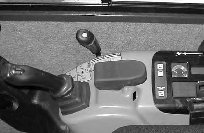
Instruments And Consoles
Cab Interior Light (If Equipped)
Press the button (Item 1) [A] to turn the light ON. Press again to turn OFF.
Left Console [B]
1. Left Control Lever (Joystick) – (See HYDRAULIC CONTROLS Page 11.
2. Horn – Press the button on the Control Lever to sound the horn.
Heater / Air Conditioner (With Cab Option Only)
3. Fan Motor – Turn clockwise to increase fan speed; counterclockwise to decrease. There are four positions; OFF – 1 – 2 – 3.
4. Air Conditioner – Press the top of the switch to turn the Air Conditioner ON (light in switch will be ON); press bottom to turn OFF.

5. Temperature Control – Turn clockwise to increase temperature; counterclockwise to decrease.
Switches
6.Future Use
7.Future Use
8. Wiper / Washer Switch – Press the switch to the left to start the wiper. The switch will stay in this position.


Press to the right to turn the wiper OFF.
Press and hold to the left to turn the washer ON to help clean the window. The switch will return to the ON position when released
9.Future Use
Wiper / Washer Fluid Reservoir (If Equipped)

The reservoir (Item 1)[C] is located under the access cover on the right side of the excavator.
Use an antifreeze washer solution in freezing temperatures.
INSTRUMENTS AND CONSOLES (Cont’d)
Right Console [A]
1. Right Control Lever (Joystick) – (See HYDRAULIC CONTROLS Page 11.)


2. Auxiliary Hydraulics Switch – Controls the fluid flow to the auxiliary quick couplers (attachment). ♦
3. Blade Control Lever – Controls raising and lowering the blade. (See BLADE CONTROL LEVER, Page 14.)
4. Two–Speed Button – Engages and disengages High Range travel speed. (See TWO–SPEED TRAVEL, Page 6.)
5. Speed Control Lever – Controls the RPM of the engine.
6. Key Switch (STANDARD Panel Only) – (Always perform the PRE–STARTING PROCEDURE Page 16 before starting the engine. See STARTING THE ENGINE Page 18.) (See Item 14 for Keyless Start.)
PREHEAT – (Early Models) For cold weather starting
STOP – Key switch OFF; engine stopped. RUN (ON)– Position when the engine is running. START – Start the engine.
NOTE:Always turn key switch and all accessories to OFF position when the engine is stopped. The battery will discharge if the key is left ON. Audible alarm will sound if the key is in the RUN position with the engine stopped.
7. Auxiliary Power Outlet – Provides 12 Volt receptacle for accessories.
8. Auxiliary Hydraulic Button – Activates and deactivates auxiliary hydraulic function.♦

9. HOURS / JOB / RPM – Press to show HOURS, JOB CLOCK or Engine RPM in LCD (Liquid Crystal Display, Item 12.) *
10. LIGHTS / HOLD FOR CODES – Press once to turn lights ON; press again to turn lights OFF. Press and hold two seconds for display of SERVICE CODES in LCD (Item 12)
11. TEMPerature Gauge – Shows the engine coolant temperature.
12. LCD (Liquid Crystal Display) – The LCD is the HOURMETER during normal operation of the excavator. When preheat is activated (Keyless Start), the LCD will show remaining preheat time. Can also be used to display JOB CLOCK or Engine RPM. *
13. FUEL Gauge – Shows the amount of fuel in the tank.
14. Keyless Start (DELUXE Panel Only) – (Always perform the PRE–STARTING PROCEDURE, Page 16 before starting the engine. See STARTING THE ENGINE Page 18.)
15. Function Icons – (See Function Icons, Page 5.)
16. JOB – On when JOB CLOCK is activated *
17. RPM – On when Engine RPM is activated *
18. ACD – On when Attachment Control Device is activated*
♦ (See Auxiliary Hydraulics, Page 13.)
* (See SYSTEM SETUP AND ANALYSIS , Page 57.)
STD / ISO SELECTOR VALVE
Move the lever (Item 1)[B] to the front (Item 2)[B] to select STANDARD Control Pattern. Move to the rear (Item 3)[B] to select ISO Control Pattern. (See HYDRAULIC CONTROLS , Page 11.)
INSTRUMENTS AND CONSOLES (Cont’d) Function Icons
The right console contains the instrument panel with Function Icons [A].

The table below shows the Icons, their function and other important information.
pressed,
2 Two–SpeedOFF– –– –– –TravelCONTINUOUS– –– –Two–Speed activated, High Range engaged FLASHING3 BeepsError
NOTE: Two–Speed is disabled during high engine coolant temperature or high hydraulic fluid temperature.
Oil Pressure is extremely low – Engine will stop in 10 seconds.
– • Hydraulic OilFLASHING3 BeepsWarning ◊ Error with Hydraulic Filter FilterCONTINUOUS3 BeepsError ◊ Hydraulic Oil Temperature out of range
TemperatureCONTINUOUS3 BeepsWarning ◊ Hydraulic Filter plugged or temperature high FLASHINGCONTINUOUSShutdown ◊ Hydraulic Oil Temp. extremely high – Engine will stop in 10 seconds. NOTE: Two–Speed is disabled during high engine coolant temperature or high hydraulic fluid temperature.
8 OFF– – •
GeneralCONTINUOUS3 BeepsError ◊ Error with one or more engine, hydraulic, or fuel functions.
WarningCONTINUOUS3 BeepsWarning ◊ Low fuel, engine speed high, coolant temperature high FLASHINGCONTINUOUSShutdown ◊ Coolant temperature or engine speed extremely high – Engine will stop in 10 seconds.
9 KeypadCONTINUOUS3 BeepsError ◊ Engine Oil Pressure sender out of range.
UnlockedCONTINUOUS3 BeepsWarning ◊ Engine oil level low.
FLASHINGCONTINUOUSShutdown ◊ Engine oil pressure very low. Engine will shutdown in 10 seconds.
10 Seat BeltON– –– –Light stays on for 45 seconds to remind operator to fasten seat belt.
• This is the normal operating condition.
◊ These functions are monitored and have SERVICE CODES associated with them. See SYSTEM SETUP & ANALYSIS Page 57 for descriptions of SERVICE CODES.
INSTRUMENTS AND CONSOLES (Cont’d)
Raising And Lowering The Console
Raise the console before exiting the cab. Pull up on the release handle (Item 1)[A]. The lift spring will assist in raising the console.


Lower the console before operating the excavator. Push down on the console [B] until the latch is engaged.
NOTE:When the console is raised, the hydraulic and traction system functions are locked and will not operate.
TWO–SPEED TRAVEL
Push the button (Item 1) [C] to engage the High Range. Press again to disengage.
TAILGATE Opening And Closing
Pull the lever (Item 1) [D] to release the tailgate latch. Pull the tailgate open to provide access for service. Firmly push the tailgate closed to engage the latch. The tailgate release can be locked (Item 2)[D]. Use the key to unlock.


OPERATOR CANOPY (ROPS / TOPS)
The excavator has an operator canopy (ROPS/TOPS) (Roll Over Protective Structure/Tip Over Protective Structure) as standard equipment. The ROPS/TOPS meets ISO 12117.
An enclosed cab (ROPS/TOPS) is an Option or can be installed as a Field Accessory.

Both the cab and canopy provide operator protection ifthe excavator is tipped over. The seat belt must be worn for ROPS /TOPS protection.
Never modify operator cab by welding, grinding, drilling holes or adding attachments unless instructed to do so by Melroe Company. Changes to the cab can cause loss of operator protection from rollover and falling objects, and result in injury or death.
W–2069–1285
FALLING OBJECT GUARDS (FOGS)
A cab or canopy FOGS (Falling Object Guards) (Item 1)[A] is available as a field installed accessory.

The FOGS provides additional protection from heavier objects which fall on the cab/canopy.
For the cab or canopy to meet the FOGS (Falling Object Guards) (ISO 10262–level 1), the excavator must have the overhead guard (Item 1) and Special Application Kit (Item 2) [A] installed.
See your excavator dealer to order these kits.
Canopy Enclosure
A vinyl canopy enclosure kit [B] is available as a Field Accessory.
See your excavator dealer to order this part.
SLEW LOCK
Move the lever (Item 1) [A] down to engage the Slew Lock. When the Slew Lock is engaged (locked), the upperstructure of the excavator is locked to the track frame and will not rotate. The upper structure must be parallel to the track frame to engage the Slew Lock.
Move the lever (Item 2) [A] up to disengage the upperstructure from the track frame. Secure the lever in the unlocked position.

Avoid Injury
The Slew Lock lever must be engaged when transporting the machine.

OPERATOR CAB (ROPS / TOPS) (If Equipped)
Emergency Exit
The left door and right rear window provide exits. Slide the window to the front of the excavator and exit through the side window [B].

Cab Door
The cab door can be locked with the same key as the starter switch (if equipped).
Push the door all the way open (Item 1) [C] until the latch engages to hold the door in the open position.
Firmly pull the door away from the cab (Item 2) [C] to disengage the latch and close the door.

Front Window
The front window is equipped with a wiper (Item 1)[D] and washer.
OPERATOR CAB (ROPS / TOPS) (Cont’d)
Front Window (Cont’d)
Opening The Front Window
Release the lower window latch pins and turn to the unlocked position [A].

Turn the two top latches (Item 1) [B] to the unlocked position.
Use both window grab handles to pull the top of the window in [C].
Continue moving the window in and upover the operator’s head until the window engages the pocket at the top, rear of the cab.

Hold the bottom of the window up and lock the two window latch pins. Make sure that the pins are secured to hold the window up [D].
Closing The Front Window
Hold the bottom of the window up and release both window latch pins and put them in the unlocked position [D]
Use both window grab handles to pull the window down[C]
Rotate the top latches (Item 1) [B] to the locked position.

Lock the window latch pins[A] at the bottom of the window.

STEERING LEVERS / FOOT PEDALS

Forward And Reverse Travel
NOTE:The following procedures describe forward, reverse, left & right as seated in the operator’s seat.
Put the blade so that it is at the front of the machine (as you sit in the operator’s seat). Slowly move both steering levers* (Item 1) [A] forward for forward travel; backward for reverse travel.
*Travel can also be controlled with foot pedals (Item 2)[A]. Pivot the heel of the pedals forward for additional space on the floor.
Avoid Injury Or Death
• Check the blade location before traveling. When the blade is to the rear, operate the steering levers/foot pedals in the opposite direction to when the blade is in the front.
• Move the steering levers/foot pedals slowly. Abrupt lever motion will cause the machine to jerk.
W–2235–0396
Turning
Right Turn
Push the left steering lever forward to turn right [B] while traveling forward.
Pull the left steering lever backward to turn right [D] while traveling backward.
Counter–Rotation Right Turn
Push the left steering lever forward and pull the right steering lever backward [F] .
Left Turn
Push the right steering lever forward to turn left [C] while traveling forward.
Pull the right steering lever backward to turn left [E] while traveling backward.
Counter–Rotation Left Turn
Push the right steering lever forward and pull the left steering lever backward [G]
HYDRAULIC CONTROLS ISO Control Pattern
The work equipment (backhoe and upper structure swing) is operated by using the left and right control levers (joysticks) [A] & [B].
Left Control Lever
The left lever is used to operate the arm and to swing the upperstructure [A]:
1.Arm out.
2.Arm out and slew right.
3.Slew right.
4.Arm in and slew right.
5.Arm in.
6.Arm in and slew left.
7.Slew left.
8.Arm out and slew left.
Right Control Lever
The right lever is used to operate the boom and bucket[B]


1.Boom lower.
2.Boom lower and bucket dump.
3.Bucket dump.
4.Boom raise and bucket dump.
5.Boom raise.
6.Boom raise and bucket curl.
7.Bucket curl.
8.Boom lower and bucket curl.
Avoid Injury Or Death
Before leaving the machine:
• Lower the work equipment to the ground.
• Lower the blade to the ground.
• Stop the engine. Remove the key.W–2196–0595
HYDRAULIC CONTROLS (Cont’d)
Standard Control Pattern
The work equipment (backhoe and upper structure swing) is operated by using the right and left control levers (joysticks) [A] & [B].
Left Control Lever
The left lever is used to operate the boom and swing the upperstructure [A]:
1.Boom Lower.
2.Boom Lower and Slew Right.
3.Slew Right.
4.Boom Raise and Slew Right.
5.Boom Raise.
6.Boom Raise and Slew Left.
7.Slew Left.
8.Boom Lower and Slew Left.
Right Control Lever
The right lever is used to operate the arm and bucket [B]:

1.Arm Out.
2.Arm Out and Bucket Dump.
3.Bucket Dump.
4.Arm In and Bucket Dump.
5.Arm In.
6.Arm In and Bucket Curl.
7.Bucket Curl.
8.Arm Out and Bucket Curl.
AVOID INJURY OR DEATH
Before leaving the machine:
• Lower the work equipment to the ground.
• Lower the blade to the ground.
• Stop the engine. Remove the key.W–2196–0595
HYDRAULIC CONTROLS (Cont’d)
Quick Couplers
Excavators and attachments have flush faced couplers (Item 1) [A].

Hydraulic fluid, tubes, fittings and quick couplers can get hot when running machine and attachments. Be careful when connecting and disconnecting quick couplers.
To Connect:
Remove any dirt or debris from the surface of both the male and female couplers, and from the outside diameter of the male coupler. Visually check the couplers for corroding, cracking, damage, or excessive wear, if any of these conditions exist, the coupler(s) (Item 1) [A] must be replaced.
Install the male coupler into the female coupler. Full connection is made when the ball release sleeve slides forward on the female coupler.
To Disconnect:
Hold the male coupler. Retract the sleeve on the female coupler until the couplers disconnect.

NOTE:Some machines may have a locking sleeve on the female coupler. The pin and groove (Items 1 & 2) [B] must be aligned for the sleeve to move for connection and disconnection.
Auxiliary Hydraulics
Press the Auxiliary Hydraulics button on the right console (Item 1) [C].
Move the switch (Item 2)[C] on the right control lever to the right or left to direct fluid flow to an attachment such a hydraulic clamp.

Continuous Flow
After pressing the Auxiliary Hydraulics button, press the front switch (Item 3)[C] on the front of the right control lever to give the quick couplers a constant flow of fluid with the female coupler being pressurized (Example: Operate a trench compactor.
To release from continuous operation, press the front switch (Item 3) [C] a second time.
Relieving Hydraulic Pressure
Stop the engine and turn the key to RUN (Standard) or press ENTER CODE Button (Deluxe).
Press AUX HYD Button (Item 1) [C] and then move the switch (Item 2) [C] to the right and left several times.

HYDRAULIC CONTROLS (Cont’d)
Two–Way Flow / One–Way Flow (Breaker Operation) (Field Accessory)
A flow control valve which allows for reduced backpressure necessary for breaker operation is available.
Pull the knob (Item 1) [A] up and install the stop on the spool to hold it in the engaged position (see decal).
Be sure to change again when not using the breaker attachment.
Blade Control Lever


Push the lever forward to lower the blade (Item 1) [B]
Pull the lever backward to raise the blade (Item 2) [B].
NOTE:Keep the blade lowered when digging to help stabilize machine.
Boom Swing Pedal
Release the pedal lock and pivot the heel of the pedal to the rear (Item 1) [C].
Push the toe of the pedal (Item 2)[C] to swing the boom to the right; push the heel of the pedal (Item 3) [C] to swing left.
NOTE:The purpose of the boom swing pedal is to offset the boom with respect to the upperstructure for digging close to a structure [D].

Daily Inspection
Check the following items before each day of operation:
Maintenance work must be done at regular intervals. Failure to do so will result in excessive wear and early failures. The Service Schedule [A] is a guide for correct maintenance of the Bobcat Excavator. It is located inside the rear door of the excavator and also in the MACHINE SIGN TRANSLATION SECTION Page 63.
• Operator Canopy or Cab (ROPS/TOPS) and mounting hardware.
• Seat belt and mounting hardware.
• Damaged decals, replace as needed.
• Check control console lockout.
• Air cleaner and intake hoses.
• Engine oil level and for engine leaks.
• Hydraulic fluid level and system for leaks.
• Grease all pivot points.
• Cylinder and attachment pivot points.
• Track Tension.
• Repair broken and loose parts.
Instructions are necessary before operating or servicing machine. Read Operation & Maintenance Manual, and signs (decals) on machine. Follow warnings and instructions in the manuals when making repairs, adjustments or servicing. Check for correct function after adjustments, repairs or service. Failure to follow instructions can cause injury or death.
Fluids such as engine oil, hydraulic fluid, coolants, etc. must be disposed of in an environmentally safe manner. Some regulations require that certain spills and leaks on the ground must be cleaned in a specific manner. See local, state and federal regulations for correct disposal.
PRE–STARTING PROCEDURE
Read and understand the Operation & Maintenance Manual and the Operator’s Handbook (Item 1) [A] before operating.
The Operation & Maintenance Manual and other manuals can be kept in a container (Item 2)[A] provided behind the operator’s seat.


Use the grab handles, the tracks and the safety treads to enter the canopy/cab [B]
Release the seat lever (Item 1) [C] to adjust the seat forward or backward.
Turn the handle (Item 2) [C] to change the adjustment for operator weight.
Release the lever (Item 3) [C] to change the incline of the seat back.
Sit in the seat and turn the knob (Item 4) [C] to adjust the height of the seat. (Zero (O) adjustment is the lowest; III is highest.)
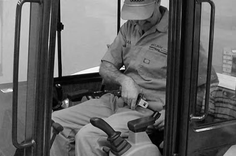
PRE–STARTING PROCEDURE (Cont’d)
Fasten the seat belt [A].
Lower the control console [B].
NOTE:There is a control lock switch in the left console which deactivates the hydraulic control levers (joysticks) and the traction drive system when the control console is raised. The console must be in the locked down position for the hydraulic control levers (joysticks) and traction system to operate.

NOTE:If the control lock switch does not deactivate the control levers and traction system when console is raised, see your Bobcat dealer for service.
STARTING THE ENGINE Key Switch
Perform the PRE–STARTING PROCEDURE Page 16. Put control levers (Item 1) [A] in the neutral position.

Move
(Early Models) Turn the key to PREHEAT position and hold for maximum of 15 seconds.
Turn the key to the RUN position. If the Preheat Icon comes on, wait for it to go off.
Turn the key to START [C] and release the key when the engine starts. It will return to the RUN position.

Stop the engine if the warning lights and alarm do not go OFF. Check for the cause before starting the engine again.
Turn the key switch OFF to stop the engine.
Do not engage the starter for longer than 15 seconds at a time. Longer use can damage the starter by overheating. Allow starter to cool for one minute before using starter again.
I–2034–0700
STARTING THE ENGINE Keyless Start
Perform the PRE–STARTING PROCEDURE Page 20. Put control levers (Item 1) [A] in the neutral position.
Move the engine speed control to low idle [B]
Press ENTER CODE Button (Item 1) [C]. The display will become lighted and there will be two short beeps.CodE will appear on the LCD.
Use the keypad (Item 2) [C] to enter the password. For each digit that you enter, a dash will appear on the LCD. (You have 40 seconds to enter the password or the process will abort and you will need to start over.) If the password was entered correctly, there will be one long beep.
NOTE: If the password was incorrect there will be three short beeps and “Error” will appear on the LCD. Press the ENTER CODE Button again and start over. After three failed attempts, you must wait three minutes to try again.
Press the START Button (Item 3) [C] and hold it until the engine starts.


Do not engage the starter for longer than 15 seconds at a time. Longer use can damage the starter by overheating. Allow starter to cool for one minute before using starter again.
I–2034–0700
Press the STOP Button (Item 4) [C] to stop the engine.
Password Lockout Feature
See SYSTEM SETUP AND ANALYSIS , Page 57 for Password Lockout Feature.
STARTING THE ENGINE (Cont’d)
Avoid Injury Or Death
When an engine is running in an enclosed area, fresh air must be added to avoid concentration of exhaust fumes. If the engine is stationary, vent the exhaust outside. Exhaust fumes contain odorless, invisible gases which can kill without warning.
• Engines can have hot parts and hot exhaust gas. Keep flammable material away.
• Do not use machines in atmosphere containing explosive gas.
Cold Temperature Starting Procedure
If the temperature is below freezing, perform the following to make starting the engine easier:
• Replace the engine oil with the correct type and viscosity for the anticipated starting temperature. (See FUEL, COOLANT AND LUBRICANTS, Page 81.)
• Make sure the battery is fully charged.
• Install an engine heater.
NOTE:If the battery is discharged (but not frozen) a booster battery can be used to jump start the excavator. (See Using A Booster Battery Page 44.)

Push the speed control lever fully forward [A]
Key Switch (Standard Panel)
(Early Models) Turn the key to PREHEAT position and hold for maximum of 15 seconds.
Turn the key to RUN and wait for the Preheat Icon [B] to go off. Turn the key to START [B] and release the key when the engine starts. It will return to the RUN position.
When the engine speed increases, move the speed control lever to idle position until the engine warms.
Keyless Start (Deluxe Panel)
Follow STARTING PROCEDURE (Keyless Start) Page 19.
If the preheat icon [B] comes ON, wait for it to go off before pressing the START Button.
The remaining preheat time (in seconds) will count down in the LCD.
Do not engage the starter for longer than 15 seconds at a time. Longer use can damage the starter by overheating. Allow starter to cool for one minute before using starter again.
Machines warmed up with moderate engine speed and light load have longer life.
Do not use ether with glow plug (preheat) systems. Explosion can result which can cause injury or death, or severe engine damage.
ATTACHMENTS (Using the X–Change™ System)
Removing Bucket or Attachment
The excavator is equipped with the X–Change™ system. The X–Change™ is used for fast changing of buckets and attachments.
NOTE:Removal and Installation of the bucket is shown. The procedure is the same for other attachments. Disconnect any hydraulic lines that are operated by hydraulic power before removing any attachments (breaker, auger, etc.).
Stop the machine on a flat level surface. Put the bucket on the ground.
Install the X–Change™ tool (Item 1) [A] in the latch. (The tool is stored in the tailgate.)


Pull the tool (Item 1) [A] to unlock the latch. Remove the tool.
Start the engine, lift the boom approximately one foot, and extend the bucket cylinder until the X–Change™ pins (Item 1) [B] engage the hooks (Item 2) [B] on the bucket.
Retract the bucket cylinder and lower the boom and arm until the bucket is on the ground, andthe X–Change™ pins (Item 1) [C] are disengaged from the hooks (Item 2) [C]
Move the arm toward the machine until the X–Change ™ pins are clear of the bucket.
ATTACHMENTS (Using the X–Change™ System) (Cont’d)
Installing Bucket or Attachment
Never use attachments or buckets which are not approved by Bobcat. Buckets and attachments for safe loads of specified densities are approved for each model. Unapproved attachments can cause injury or death.

W–2052–0100
Fully retract the bucket cylinder to release the latch on the X–Change™ [A]


Move the arm toward the bucket.
Raise the boom until the pins (Item 1)[B] engage the hooks (Item 2) [B] on the bucket.
Lift the boom and extend the bucket cylinder until the bucket is in the position shown [C].
Lower the boom until the hooks (Item 1) [D] of the bucket disengage the pins (Item 2) [D] of the X–Change™ and the plate (Item 3) [D] engages in the bucket crossmember.
Keep all bystanders 20 feet (6 m) away from equipment when operating. Contact with moving parts, a trench cave–in or flying objects can cause injury or death.
W–2119–0788
After the installation of the bucket, lift the boom approximately three feet and fully extend and retract the bucket cylinder to ensure the bucket is securely attached to the X–Change™
OPERATING PROCEDURE Operating On Public Roads
When operating on a public road or highway, always follow local regulations. For example: A slow moving vehicle (SMV) sign, or direction signals may be required.
Check with utility companies for underground electrical, water, gas lines, etc. Work slowly in areas of underground utilities.
AVOID INJURY OR DEATH
Do not exceed rated operating capacity. Excessive load can cause tipping or loss of control.
Lifting A Load
Do not exceed the rated load capacity. (See MACHINE SIGNS & TRANSLATIONS – Lifting Decal, Page 63.)
Extend the bucket cylinder completely and lower the boom to the ground. Stop the engine.
Wrap the chain assembly around the bucket mounting plate.
Make sure the load is evenly weighted and centered on the lifting chain, and is secured to prevent the load from shifting [A]

Lift and position the load. When the load is in position and tension is removed from the lift chain (secondary lift system), remove the secondary lift system.
The optional lifting clamp attachment gives the excavator a wider range of use and mobility for debris removal [B]
The lifting clamp is operated by the auxiliary hydraulic system.
The lifting clamp cylinder must be fully retracted when the machine is being used for excavating.
The lift capacities are reduced by 270 lbs. (122 kg) if the excavator is equipped with the optional lifting clamp.
AVOID INJURY OR DEATH
Check area to be dug for overhead or underground lines such as electrical, gas, oil, water, etc. Consult local utilities before digging. Extreme caution must be used in areas where lines are present.
OPERATING PROCEDURE (Cont’d)
Excavating
Lower the blade to provide stability.
Extend the arm, lower the boom and open the bucket [A].
Retract the arm, while lowering boom and curling the bucket [B]
Raise the boom, retract the arm and curl the bucket [C] Rotate the upperstructure.
NOTE:Do not allow the bucket teeth to contact the ground when swinging the upperstructure.
Keep all bystanders 20 feet (6 m) away from equipment when operating. Contact with moving parts, a trench cave–in or flying objects can cause injury or death.
W–2119–0788
Extend the arm and uncurl the bucket todump the material into a pile or truck [D]
Avoid operating hydraulics over relief pressure. Failure to do so will overheat hydraulic components.
I–2220–0503
OPERATING PROCEDURE (Cont’d)
Excavating (Cont’d)
Do not dig under the excavator [A].
Do not use the bucket as abreaker or pile driver. It is better to excavate hard or rocky ground after breaking it with other equipment. This will reduce damage to the excavator.
Do not move the excavator while the bucket is in the ground.
Dig only by moving the boom and arm toward the excavator.
Do not back dig (digging by moving the boom and arm away from the excavator). Damage to the X–Change and attachments may occur.
Boom Offset
Swing the upperstructure, offset the boom to the right [B], center [C], and left [D] to dig a square hole the width of the machine without repositioning the excavator.
OPERATING PROCEDURE (Cont’d)
Boom Offset (Cont’d)
The boom offset allows the operator to dig close to buildings and other structures [A]
Backfilling
Use the blade to backfill the trench or hole afterexcavating [B]
B
Driving The Excavator
When operating on uneven ground, operate as slow as possible and avoid sudden changes in direction. Avoid traveling over objects such as rocks, trees, stumps, etc.
When working on wet or soft ground, put planks on the ground to provide a solid base to travel on and preventthe excavator from getting stuck.
If one or both tracks have become stuck in soft or wet ground, raise one track at a time by turning the upperstructure and pushing the bucket against the ground [C]
Put planks under the tracks and drive the excavator to dry ground.
The bucket may also be used to pull the excavator. Raise the blade, extend the arm and lower the boom. Operatethe boom and arm in a digging manner [D]
OPERATING PROCEDURE (Cont’d)
Operating On Slopes
When going down a slope, control the speed with the steering levers and the speed control lever.
When going down grades that exceed 15 degrees, put the machine in the position shown, and run the engine slowly [A]
Operate as slow as possible and avoid sudden changesin lever direction.
Avoid traveling over objects such as rocks, trees, stumps, etc.
Stop the machine before moving the upper equipment controls. Never allow the blade to strike a solid object. Damage to the blade or hydraulic cylinder can result.
When traveling up slopes or on side slopes that are 15 degrees or less, position the machine as shown and run the engine slow [B]
Avoid Injury Or Death
• Do not travel across or up slopes which are over 15 degrees to the side, or to the back of machine or 25 degrees to the front. Keep boom centered while traveling.
• Keep attachments as low as possible when traveling on slopes or in rough conditions.
• Fasten seat belt, start and operate only from the operator seat.
• Never wear loose clothing when working near machine.
OPERATING PROCEDURE (Cont’d) Operating On Slopes (Cont’d)
When operating on a slope, level a work area [A] before beginning.
If this is not possible, the following procedures should be used:
Do not work on slopes which are over 15 degrees. Use a slow work cycle.
Avoid working with the tracks across the slope. This will reduce stability and increase the tendency for the machine to slide. Position the excavator with the blade downhill and lowered.
Avoid swinging or extending the bucket more than necessary in a down hill direction. When you must swing the bucket downhill, keep the arm low and skid the bucket downhill.
When working with the bucket on the uphill side, keep the bucket as close to the ground as possible. Dump the spoil far enough away from the trench or hole to prevent the possibility of a cave in.
To brake the machine when going down a slope, move the steering levers (Item 1) [B] to the NEUTRAL position. This will engage the hydrostatic braking.
When the engine stops on a slope, move the steering levers to the neutral position. Lower the boom/bucket to the ground.
NOTE:If the engine stops, the boom/bucket (attachments) can be lowered to the ground using hydraulic pressure which is stored in the accumulator.
The console must be in the locked down position, and the key switch in the ON position.
Use the control lever to lower the boom. Start the engine and resume operation.
OPERATING PROCEDURES (Cont’d) Operating In Water
Mud and water should be removed from the machine before parking. In freezing temperatures, park the machine on boards or concrete to prevent the track or undercarriage from freezing to the ground and preventing machine movement.
Do not operate or immerse the Excavator in water higher than the bottom of the swing circle [A]
Grease the Excavator when it has been operated or immersed in water for a period of time. Greasing forces the water out of the lubrication areas.
Water must be removed from the cylinder rods. If water freezes to the cylinder rod, the cylinder seals can be damaged when the rod is retracted.
Parking The Excavator
Stop the machine on level ground. Lower the work equipment and the blade to the ground.
Run the engine at idle speed for about 5 minutes to allow it to cool.
Move the speed control lever fully backward [B].
Turn the key switch to STOP (Standard Panel) or press the STOP Button (Deluxe Panel) (Item 1) [C]
Disconnect the seat belt. Remove the key from the switch to prevent operation of machine by unauthorized personnel. Exit machine.

Transporting The Excavator
When transporting the machine, observe the rules, motor vehicle laws and vehicle limit ordinances. Use a transport and towing vehicle of adequate length and capacity.
Secure the parking brakes and block the wheels of the transport vehicle.
Align the ramps with the center of the transport vehicle. Secure the ramps to the truck bed and be sure ramp angle does not exceed 15 degrees.
Use metal loading ramps with a slip resistant surface.
Use ramps that are the correct length and width, and can support the weight of the machine.

The rear of the trailer must be blocked or supported when loading or unloading the excavator to prevent the front of the transport vehicle from raising.
Determine the direction of the track movement before moving the machine (blade forward).
Move the machine forward onto the transport vehicle [A].
Do not change direction of the machine while it is on the ramps.
Lower the boom, arm, bucket and blade to the transport vehicle.
Stop the engine and remove the key (if equipped).
Put blocks at the front and rear of the tracks.
Fasten chains to the front corners of the blade (Item 1) [B] and to the tie down loop at the rear (Item 2) [B] to prevent it from moving when going up or down slopes, or during sudden stops.
Use chain binders to tighten the chains and then safely tie the chain binder levers to prevent loosening.
Adequately designed ramps of sufficient strength are needed to support the weight of the machine when loading onto a transport vehicle. Wood ramps can break and cause personal injury.


Lifting The Excavator
Fully extend the cylinders of the bucket, arm &boom so that the excavator is in the position as shown [A]
Raise the blade all the way.
Put the all control levers in neutral .
Avoid Injury Or Death
• Use a lifting fixture with sufficient capacity for the weight of the excavator plus any added attachments.


• Maintain center of gravity and balance when lifting.

• Do not swing boom or upperstructure. Engage the swing locking lever.
• Never lift with operator on machine.
W–2202–0595
Fasten chains to the ends of the blade (Item 1) [A] & [B] and up to a lifting fixture above the canopy/cab. The lifting fixture must extend over the sides of the canopy/cab to prevent the chains from hitting the ROPS/TOPS.
Install a 1 inch (25mm) bolt and nut (Grade 5 or 8)through the holes at the top of the boom (Item 2) [A] & [B]. Fasten a chain from the bolt to the lift fixture.