11 minute read
MONITORING THE DISPLAY PANELS


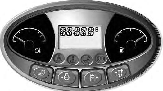
Instrument Panel
Figure93
Frequently monitor the temperature and fuel gauges [Figure93]
After the engine is running, frequently monitor the instrument panel [Figure93] for machine condition.
The associated icon is displayed if there is an error condition.
EXAMPLE: Engine Coolant Temperature is High.
The Engine Coolant Temperature icon (Item 1) [Figure93] is ON.
Press the Information button (Item 2) (Standard Panel) or press a scroll button (Item 3) [Figure93] (Deluxe Panel) repeatedly to cycle the data display until the service code screen is displayed. One of the following SERVICE CODES is displayed.
• [M0810] Engine Coolant Temperature Too High
• [M0811] Engine Coolant Temperature Extremely High
Find the cause of the service code and correct before operating the excavator again. (See DIAGNOSTIC SERVICE CODES on Page 155.)
NOTE:The optional Deluxe Instrumentation Panel offers an additional view of service codes that includes a brief description. (See DIAGNOSTIC SERVICE CODES on Page 155.)

Warning And Shutdown
When a WARNING condition exists; the associated icon light is ON and the alarm sounds 3 beeps. If this condition is allowed to continue, there may be damage to the engine or hydraulic systems.
When a SHUTDOWN condition exists; the associated icon light is ON and the alarm sounds continuously. The monitoring system will automatically stop the engine in 15 seconds. The engine can be restarted to move or relocate the excavator.
The SHUTDOWN feature is associated with the following icons:
General Warning
Engine Malfunction
Engine Coolant Temperature
Hydraulic Fluid Temperature
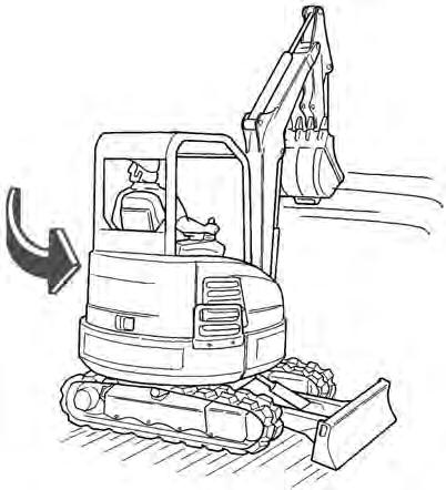
STOPPING THE ENGINE AND LEAVING THE EXCAVATOR
Procedure
Figure94
Stop the machine on level ground. Lower the work equipment and the blade to the ground [Figure94]
Disconnect the seat belt. Remove the key from the switch (If Equipped) to prevent operation of machine by unauthorized personnel. Raise the control console and exit the machine.
Rotate the engine speed control dial (Item 1) [Figure95] counterclockwise to low idle.
Run the engine at idle speed for about 5 minutes to allow it to cool.

Attachments
Installing And Removing The Attachment (Pin-On X-Change)
Installation
NOTE: Installation and removal of the bucket is shown. The procedure is the same for other attachments. Disconnect any hydraulic lines that are operated by hydraulic power before removing any attachments (breaker, auger, etc.).
Warning
AVOID INJURY OR DEATH
Never use attachments or buckets which are not approved by Bobcat Company. Buckets and attachments for safe loads of specified densities are approved for each model. Unapproved attachments can cause injury or death.
W-2052-0907

Warning
Both hydraulic pins must be fully extended through the attachment mounting holes and locked with both retainer pins and clips. Failure to fully engage and lock hydraulic pins can allow attachment to come off and cause serious injury or death.

W-2507-0706
Apply a light coat of grease to the ends of the pin (Item 2) [Figure97]
Inspect the pin (Item 1) [Figure97] for wear or damage. Replace the pin as needed.
Start the engine and move the arm toward the bucket [Figure98]
ATTACHMENTS (CONT’D)
Installing And Removing The Attachment (Pin-On X-Change) (Cont’d)
Installation (Cont’d)
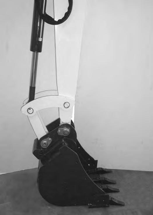
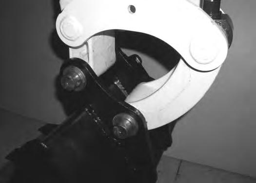
Raise the boom until the pins (Item 1) engage the hooks (Item 2) [Figure99] on the bucket.
Raise the boom and extend the bucket cylinder until the X-Change contacts the attachment back [Figure100].
With the arm vertical, lower the boom until the hooks (Item 1) of the bucket disengage the pins (Item 2) of the X-Change and the plate (Item 3) [Figure100] fully engages in the bucket crossmember.


Warning
Keep all bystanders 6 m (20 ft) away from equipment when operating. Contact with moving parts, a trench cave-in or flying objects can cause injury or death.
W-2119-0910
ATTACHMENTS (CONT’D)
Installing And Removing The Attachment (Pin-On X-Change) (Cont’d)
Installation (Cont’d)
Stop the engine. Turn the start key to the ON position and move both hydraulic control levers to relieve hydraulic pressure.
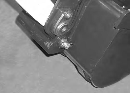

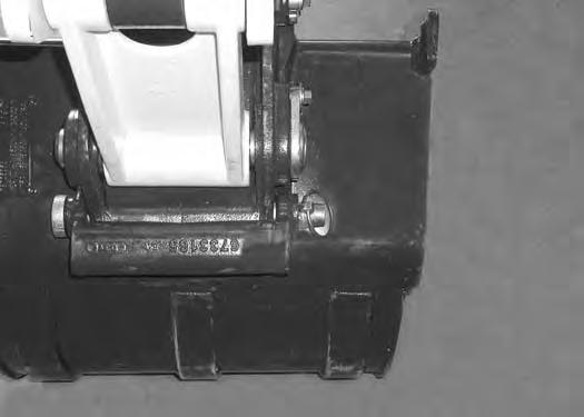
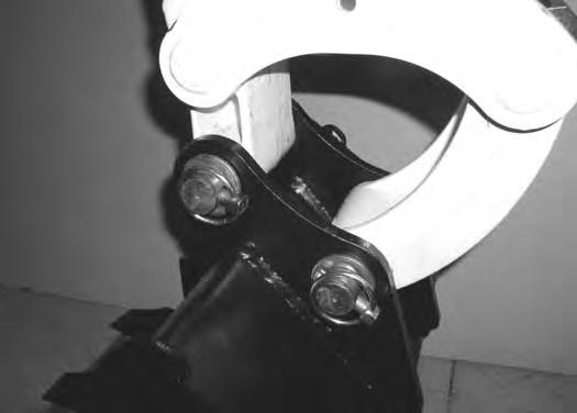
Drive the pin (Item 1) [Figure101] through the bucket mount and X-Change.
Install the retainer pin (Item 1) [Figure102]
Check for proper installation.
Lift the attachment and fully extend and retract the bucket cylinder.
ATTACHMENTS (CONT’D)
Installing And Removing The Attachment (Pin-On X-Change) (Cont’d)
Removal
Use the pin on X-Change when installing new attachments that are equipped with the pin on X-Change bracket.
NOTE: Removal and installation of the bucket is shown. The procedure is the same for other attachments. Disconnect any hydraulic lines that are operated by hydraulic power before removing any attachments (breaker, auger, etc.).
Warning
Avoid Injury Or Death
Never use attachments or buckets which are not approved by Bobcat Company. Buckets and attachments for safe loads of specified densities are approved for each model. Unapproved attachments can cause injury or death.
W-2052-0907
With the engine off, turn the start key to the ON position and move both hydraulic control levers to relieve hydraulic pressure.
ATTACHMENTS (CONT’D)
Installing And Removing The Attachment (Pin-On X-Change) (Cont’d)

Removal (Cont’d)
Warning
AVOID INJURY OR DEATH
Wear safety glasses to prevent eye injury when any of the following conditions exist:
•When fluids are under pressure.
•Flying debris or loose material is present.
•Engine is running.
•Tools are being used.
Start the engine, raise the boom approximately one foot and retract the bucket cylinder until the X-Change pins (Item 1) engage the hooks (Item 2) [Figure106] on the bucket.
ATTACHMENTS (CONT’D)
Installing And Removing The Attachment (Pin-On X-Change) (Cont’d)
Removal (Cont’d)
ATTACHMENTS (CONT’D)
Installing And Removing The Attachment (Pin-On Attachment)
Installation
Warning
AVOID INJURY OR DEATH
Stop the machine on a firm flat surface. When removing or installing attachments (such as a bucket), always have a second person in the operator’s seat, give clear signals and work carefully.
W-2140-0189
Install the two retainer pins (Item 1) [Figure109]. Install grease in the grease fittings.
Removal
Park the excavator on a flat surface and lower the bucket fully.
Remove the two retainer pins (Item 1) [Figure109].
Remove the washers and pins (Items 1 and 3) [Figure108]
Install the arm into the bucket and align the mounting hole.
Install the pin (Item 1) [Figure108] and washers.
Install the link (Item 2) in the bucket and align the mounting hole. Install the pin (Item 3) [Figure108] and washers.
Do not damage the dust seals in the arm.
Warning
AVOID INJURY OR DEATH
Never use attachments or buckets which are not approved by Bobcat Company. Buckets and attachments for safe loads of specified densities are approved for each model. Unapproved attachments can cause injury or death.
W-2052-0907
OPERATING PROCEDURE Inspect The Work Area
Before beginning operation, inspect the work area for unsafe conditions.
Look for sharp drop-offs or rough terrain. Have underground utility lines (gas, electrical, water, sewer, irrigation, etc.) located and marked. Work slowly in areas of underground utilities.
Remove objects or other construction material that could damage the excavator or cause personal injury.
Always check ground conditions before starting your work:
•Inspect for signs of instability such as cracks or settlement.
•Be aware of weather conditions that can affect ground stability.
•Check for adequate traction if working on a slope.
Basic Operating Instructions
When operating on a public road or highway, always follow local regulations. For example: A slow moving vehicle (SMV) sign, or direction signals may be required.
Run the engine at low idle speed to warm the engine and hydraulic system before operating the excavator.
Important
Machines warmed up with moderate engine speed and light load have longer life.
I-2015-0284
New operators must operate the excavator in an open area without bystanders. Operate the controls until the excavator can be handled at an efficient and safe rate for all conditions of the work area.
Operating Near An Edge Or Water
Keep the excavator as far back from the edge as possible and the excavator tracks perpendicular to the edge so that if part of the edge collapses, the excavator can be moved back.
Always move the excavator back at any indication the edge may be unstable.
Lowering The Work Equipment (Engine STOPPED)
The hydraulic control levers control the movement of the boom, arm, bucket and upperstructure slew functions.
The console must be in the locked down position, and the key switch in the ON position.
Use the control lever to lower the boom.
The joystick lock switch disengages the hydraulic control functions from the joysticks when the console are raised [Figure110].
NOTE: If the engine stops, the boom / bucket (attachments) can be lowered to the ground using hydraulic pressure in the accumulator.

The control console must be in the locked down position, and the key switch in the ON position.
Use the control lever to lower the boom.
Lower the control console to engage the hydraulic control functions of the joysticks [Figure110].
OPERATING PROCEDURE (CONT’D)
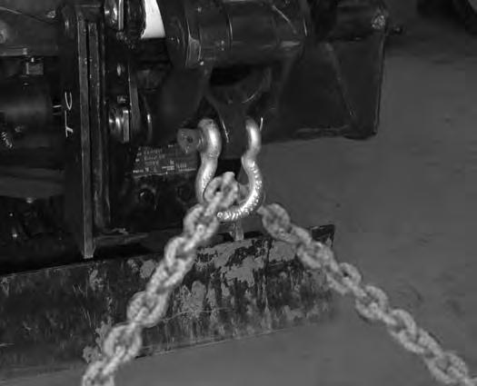
Object Handling With The Lifting Device
The excavator must be equipped with the optional lift eye link (Item 1) [Figure112], the boom and arm load hold valves and the overload warning device option. See your Bobcat dealer for available Kits.
Warning
AVOID INJURY OR DEATH
•Do not exceed rated lift capacity.
•Excessive load can cause tipping or loss of control.
•Excessive load can cause failure of the lift eye and cause the load to drop.
W-2991-0714
Do not exceed the machine’s Rated Lift Capacity or the Rated Lift Load (RLL) of the lifting device (lift eye). (See Rated Lift Capacity - Standard Arm on Page 176.), (See Rated Lift Capacity - Standard Arm W/Counterweight on Page 177.) or (See Rated Lift Capacity - Long Arm on Page 178.)
Make sure the secondary lifting system (chain) is of sufficient strength to lift the object.

Figure111
The maximum RLL (Item 1) [Figure111] is shown on the lifting device.
Extend the bucket cylinder completely and lower the boom to the ground. Stop the engine. Exit the excavator. (See STOPPING THE ENGINE AND LEAVING THE EXCAVATOR on Page 75.)
Figure112
Install the clevis (Item 2) through the lift eye (Item 1) [Figure112]
NOTE: Visually check the lifting eye, the clevis, the mounting hardware and the secondary lifting system (chain) for any damage. Replace any damage components before lifting. See your Bobcat dealer for replacement lift eye, hardware and clevis. Tighten the four lift eye mount bolts to 29 - 32 N•m (21 - 24 ft - lb) torque.
OPERATING PROCEDURE (CONT’D)
Object Handling With The Lifting Device
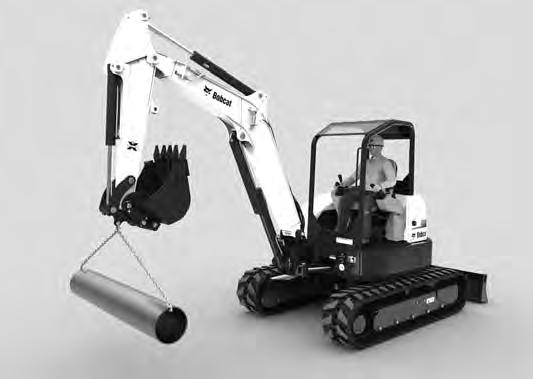
Figure113
NOTE:Always use chains or other types of lifting devices that are intended for this type of use and that are of adequate strength for the object being lifted.
Enter the excavator, fasten the seat belt and start the engine. (See PRE-STARTING PROCEDURE on Page 67.)
Make sure the load is evenly weighted and centered on the lifting chain (or other type of lifting device), and is secured to prevent the load from shifting [Figure115]
Operate the controls slowly and smoothly to avoid suddenly swinging the lifted load.
Lift and position the load. When the load is placed in a secured position and tension is removed from the lift chain, remove the chain from the load and from the lift eye.
OPERATING PROCEDURE (CONT’D)
Lift Capacity
The lifting capacities were calculated with a machine that was equipped with a standard bucket and the pin-on Xchange. The difference between the weight of the attachment and the standard bucket, the pin-on Xchange and the quick coupler (if equipped), and the hydraulic clamp (if equipped) must be subtracted.
Warning

AVOID INJURY OR DEATH
Do not exceed rated lift capacity. Excessive load can cause tipping or loss of control.
* 626 kg (1381 lb)
The following example will show how to calculate the lift capacity differences between the lift capacity charts with standard equipment and when using optional equipment.
The standard equipment weights used when determining lift capacity are as follows:
Standard Bucket = 102 kg (224 lb)
Pin-On X-Change = 26 kg (58 lb)
The following lists the weight of the optional quick couplers and hydraulic clamp:
•Pin-on X-Change = 26 kg (58 lb)
•Hydraulic Clamp And Cylinder = 45 kg (99 lb)
•Optional Buckets and Attachments (See NOTE below)
NOTE:For bucket weights, see your Bobcat dealer. For attachment weights, see the attachment Operation & Maintenance Manual.
OPERATING PROCEDURE (CONT’D)
Lift Capacity (Cont’d)
The following is an example for determining the lift capacity using the sample chart shown above [Figure116]
- Machine Position: Over Blade, Blade Down
- Lift Radius: 4000 mm (125.5 in)
- Lift Point Height: 2000 mm (78.7 in)
- Hydraulic X-Change
- Hydraulic Clamp and Cylinder
- Standard Bucket
1. Obtain Lift Capacity from Chart: 626 kg (1381 lb)
2. Subtract the difference between the weight of the standard configuration (Pin-On X-change and Standard Bucket) and optional equipment which in this case is the Hydraulic X-Change and the Hydraulic Clamp.
Quick Coupler (Pin-On X-Change minus Hydraulic X-change): 26 kg (58 lb) - 30 kg (66 lb) = minus 4 kg (8 lb) Hydraulic Clamp and Cylinder: 45 kg (99 lb)
3. Calculate actual Lift Capacity for machine as configured: 626 kg (1381 lb) - 4 kg (8 lb) (coupler difference) - 45 kg (99 lb) (hydraulic clamp and cylinder) = 578 kg (1274 lb)
* The lift capacity charts (decals) are based off of ISO 10567: 2007. The lifting capacities are defined as the lower value of 75% of tipping load or 87% of the hydraulic lift capacity.
OPERATING PROCEDURE (CONT’D)
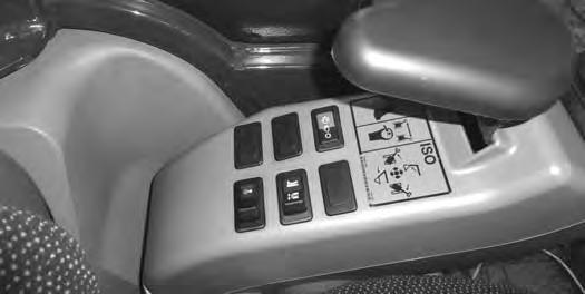
Using The Clamp (If Equipped)
Figure117
The optional lifting clamp attachment gives the excavator a wider range of use and mobility for debris removal [Figure117]
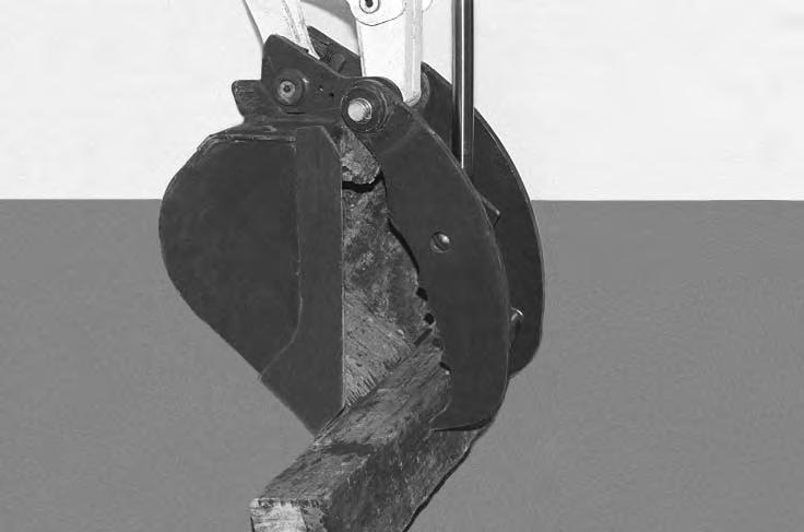
The lifting clamp cylinder must be fully retracted when the machine is being used for excavating.
The lift capacities are reduced by 122 kg (270 lb) if the excavator is equipped with the optional lifting clamp.
NOTE:Do NOT fully extend the lifting clamp cylinder if the bucket is removed. If the machine is equipped with an X-Change and the bucket and clamp cylinders are both fully extended with the bucket removed, the clamp cylinder rod will strike the X-Change and the clamp cylinder may be damage.
When Using Primary Auxiliary Hydraulics To Activate Clamp
Engage the auxiliary hydraulics and toggle to the Aux2 setting. (See Auxiliary Hydraulics - Standard Instrument Panel on Page 55.) or (See Auxiliary Hydraulics - Deluxe Instrument Panel on Page 56.)
LEFT HAND CONTROL LEVER (JOYSTICK) SECONDARY AUXILIARY HYDRAULICS
RIGHT HAND CONTROL LEVER (JOYSTICK)

PRIMARY AUXILIARY HYDRAULICS
Move the switch (Item 1) [Figure118] on the right control lever to the right to open the clamp. Move the switch to the left to close the clamp.
When Using Secondary Auxiliary Hydraulics To Activate Clamp
Move the switch (Item 2) [Figure118] on the left control lever to the left open the clamp. Move the switch to the right to close the clamp.
OPERATING PROCEDURE (CONT’D)
Excavating WARNING
AVOID INJURY OR DEATH
Check area to be excavated for overhead or underground lines such as electrical, gas, oil, water, etc. DIAL 811 (USA Only) or 1-888-258-0808 (USA & Canada) and consult local utilities before digging. Extreme caution must be used in areas where utility lines are present.
W-2686-1007
Lower the blade to increase digging performance.
Figure119
Extend the arm, lower the boom, and open the bucket [Figure119]
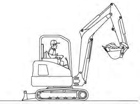
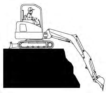

Figure120
Raise the boom, retract the arm and curl the bucket [Figure121]
Rotate the upperstructure.
NOTE:Do not allow the bucket teeth to contact the ground when swinging the upperstructure.
Warning
Keep all bystanders 6 m (20 ft) away from equipment when operating. Contact with moving parts, a trench cave-in or flying objects can cause injury or death.
W-2119-0910
Warning
AVOID INJURY OR DEATH
Check area to be excavated for overhead or underground electrical power lines. Keep a safe distance from electrical power lines.
LINE VOLTAGE MINIMUM APPROACH DISTANCE
50 kVAt least 3 m (10 ft)
230 kVAt least 5 m (17 ft)
740 kVAt least 10 m (33 ft)
W-2757-0910
Retract the arm, while lowering boom and curling the bucket [Figure120].
OPERATING PROCEDURE (CONT’D)
Excavating (Cont’d)
Figure122
Figure124
Look in the direction of rotation and make sure there are no bystanders in the work area before rotating the upperstructure [Figure122]
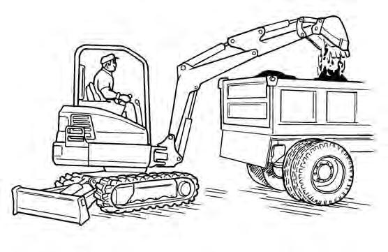
Figure123
Extend the arm and uncurl the bucket to dump the material into a pile or truck [Figure123]
Important
Avoid operating hydraulics over relief pressure. Failure to do so will overheat hydraulic components. I-2220-0503
Do not dig under the excavator [Figure124]
Do not use the bucket as a breaker or pile driver. It is better to excavate hard or rocky ground after breaking it with other equipment. This will reduce damage to the excavator.
Do not move the excavator while the bucket is in the ground.
Dig only by moving the boom and arm toward the excavator.
Do not back dig (digging by moving the boom and arm away from the excavator). Damage to the X-Change and attachments may occur.