19 minute read
MAINTENANCE SAFETY


Instructions are necessary before operating or servicing machine. Read and understand the Operation & Maintenance Manual, Handbook and signs (decals) on machine. Follow warnings and instructions in the manuals when making repairs, adjustments or servicing. Check for correct function after adjustments, repairs or service. Untrained operators and failure to follow instructions can cause injury or death.
W–2003–0199
Safety Alert Symbol:This symbol with a warning statement, means: “Warning, be alert! Your safety is involved!” Carefully read the message that follows.
Never service the Bobcat® Skid Steer Loader without instructions.
Use the correct procedure to lift or lower operator cab.
Cleaning and maintenance are required daily.
Wrong Wrong Wrong
Have good ventilation when welding or grinding painted parts. Wear dust mask when grinding painted parts. Toxic dust and gas can be produced. Avoid exhaust fume leaks which can kill without warning. Exhaust system must be tightly sealed.
Disconnecting or loosening any hydraulic tubeline, hose, fitting, component or a part failure can cause lift arms to drop. Do not go under lift arms when raised unless supported by an approved lift arm support device. Replace if damaged.
Never work on loader with lift arms up unless lift arms are held by an approved lift arm support device. Replace if damaged. Never modify equipment or add attachments not approved by Bobcat Company.
Wrong Wrong Wrong
Stop, cool and clean engine of flammable materials before checking fluids.
Never service or adjust loader with the engine running unless instructed to do so in the manual.
Avoid contact with leaking hydraulic fluid or diesel fuel under pressure. It can penetrate the skin or eyes.
Never fill fuel tank with engine running, while smoking or when near open flame.
Keep body, jewelry and clothing away from moving parts, electrical contacts, hot parts and exhaust.
Wear eye protection to guard from battery acid, compressed springs, fluids under pressure and flying debris when engines are running or tools are used. Use eye protection approved for type of welding. Keep rear door closed except for service. Close and latch door before operating the loader.
Lead–acid batteries produce flammable and explosive gases. Keep arcs, sparks, flames and lighted tobacco away from batteries.
Batteries contain acid which burns eyes or skin on contact. Wear protective clothing. If acid contacts body, flush well with water. For eye contact flush well and get immediate medical attention.
Maintenance procedures which are given in the Operation & Maintenance Manual can be performed by the owner/operator without any specific technical training. Maintenance procedures which arenot in the Operation & Maintenance Manual must be performed ONLY BY QUALIFIED BOBCAT SERVICE PERSONNEL. Always use genuine Bobcat replacement parts. The Service Safety Training Course is available from your Bobcat dealer.

Service Schedule
Maintenance work must be done at regular intervals. Failure to do so will result in excessive wear and early failures. Th e service schedule is a guide for correct maintenance of the Bobcat loader.
Instructions are necessary before operating or servicing machine. Read and understand the Operation & Maintenance Manual, Handbook and signs (decals) on machine. Follow warnings and instructions in the manuals when making repairs, adjustments or servicing. Check for correct function after adjustments, repairs or service. Untrained operators and failure to follow instructions can cause injury or death.
Engine Oil Check the oil level and add oil as needed.
Engine Air Cleaner Check condition indicator or display panel. Service only when required.
Engine Cooling SystemClean debris from oil cooler radiator & grill.
Lift Arms, Cyl., Bob–TachLubricate with multi–purpose lithium based grease Pivot Pins and Wedges(12 places).
Engine Air System Check for leaks and damaged components.
Tires Check for damaged tires and correct air pressure.
Seat Belt, Seat Bar & PedalCheck the condition of seat belt. Check the seat bar and foot Interlocks or Hand Controlpedal interlocks or hand control interlocks for correct operation.
Interlocks Clean dirt and debris from moving parts.
Bobcat Interlock ControlCheck BICS™ functions.
System (BICSTM)
Safety Signs and SafetyCheck for damaged signs (decals) and safety treads. Replace Treads any signs or safety treads that are damaged or worn.
Operator Cab Check the fastening bolts, washers and nuts. Check the condition of the cab.
Fuel Filter Remove the trapped water.
Traction Lock Control Sys.Check operation and correct as needed.
Hyd. Fluid, Hoses andCheck fluid level & add as needed. Check for damage & leaks.
Tubelines Repair or replace as needed.
Final Drive Trans.(Chaincase) Check oil level.
BatteryCheck cables, connections and electrolyte level. Add distilled water as needed.
Foot Pedals or Hand Check for correct operation. Repair or adjust as needed. Controls and Steering
Wheel NutsCheck for loose wheel nuts and tighten to 105–115 ft.–lbs. (142–156 Nm) torque.
Parking Brake Check operation of the brake.
Alternator Belt Check tension and adjust as needed.
Engine/Hydro. Drive BeltCheck for wear or damage. Check idler arm stop.
Fuel Filter Replace filter element.
Steering Shaft Grease three fittings.
Hyd. Res. Breather CapReplace the reservoir breather cap.
Hyd./ Hydro. Filter Replace the filter element.
Engine Oil and FilterReplace oil and filter. Use CD or better grade oiland Bobcat filter.
Final Drive Trans.(Chaincase) Replace the oil in the chaincase.
Hydraulic ReservoirClean or replace the fluid.
Case Drain Filters Clean or replace the case drain filters.
Bobcat Interlock ControlCheck lift arm by–pass control.
System (BICSTM)
Fan Drive Gearbox Check gear lube level.
Engine Valves Adjust the engine valves.
Engine Timing Belt Replace the timing belt and belt tensioner assy.
Check wheel nut torque every 8 hours for the first 24 hours.
W–2003–0199
*Inspect the new belt after first 50 hours. Also replace hydraulic/hydrostatic filter element when the transmission warning light comes ON. After the first 50 hours.
∞ After the first 500 hours on new engine, adjust engine valves; 1000 hours thereafter. (See Service Manual for procedure.)
Or every 12 months.
Or every 5 years.
Never work on a machine with the lift arms up unless the lift arms are secured by an approved lift arm support device. Failure to use an approved lift arm support device can allow the lift arms or attachment to fall and cause injury or death.

W–2059–0598
Service lift arm support device if damaged or if parts are missing. Using a damaged lift arm support or with missing parts can cause lift arms to drop causing injury or death.
W–2271–1197
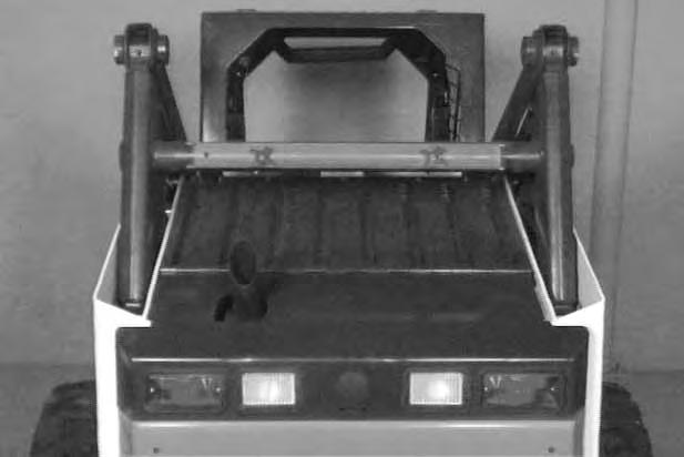
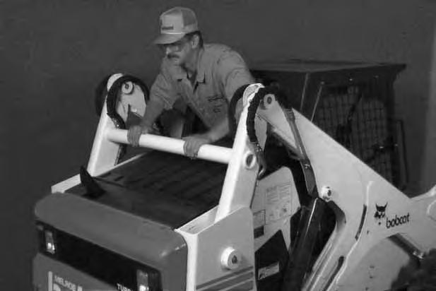
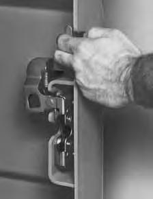
Installing The Lift Arm Support Device
Put jackstands under the rear corners of the loader frame. Remove the retainer knobs (Item 1) [A] or [B]
Remove the lift arm support device from the crossmember.
One person must stay in the operator seat [C] with the seat belt fastened and the seat bar lowered, whilesecond person installs the lift arm support device.
Start the engine, press the green PRESS TO OPERATE Button and raise the lift arms.
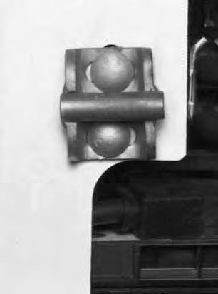
Have a second person install the lift arm support device over the rod of one of the lift cylinders [C].
The 90° notch should be installed against the outer case of the lift cylinder [C]. (See Inset.)
Lower the lift arms slowly until the support device is held between the lift arms and lift cylinder [D]
Removing The Lift Arm Support Device
Raise the lift arms while a second person removes the lift arm support device [C]
Stay in the seat until the lift arms are lowered all theway. Return the lift arm support device to the storage position and secure the retainer knobs (Item 1) [A] or [B].
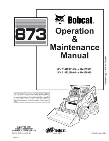
The Bobcat loader has an operator cab (ROPS and FOPS) as standard equipment to protect the operator from rollover and falling objects [A]. Check with your dealer if the operator cab has been damaged.
ROPS/FOPS – Roll Over Protective Structure per SAE J1040 and ISO 3471, and Falling Object Protective Structure per SAE J1043 and ISO 3449, Level l. Level ll is available.
Level l – Protection from falling bricks, small concrete blocks and hand tools encountered in operations such as highway maintenance, landscaping, and other construction site services.
Level ll – Protection from falling trees, rocks; for machines involved in site clearing, overhead demolition or forestry.
Never modify operator cab by welding, grinding, drilling holes or adding attachments unless instructed to do so by Bobcat Company. Changes to the cab can cause loss of operator protection from rollover and falling objects, and result in injury or death.
W–2069–1285
Before the cab or the lift arms are raised for service, jackstands must be put under the rear corners of the frame. Failure to use jackstands can allow the machine to tip backward causing injury or death.
W–2014–0895
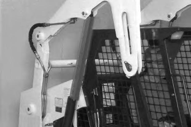
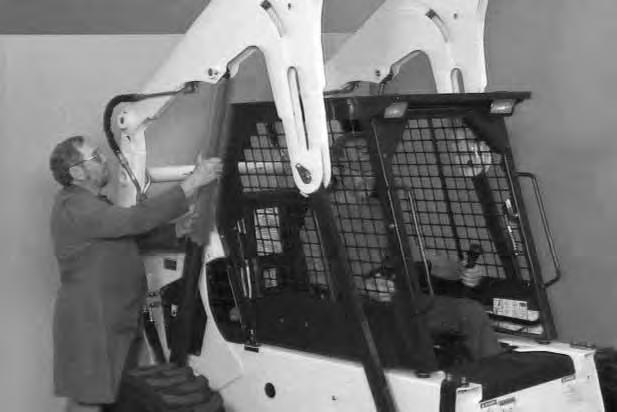
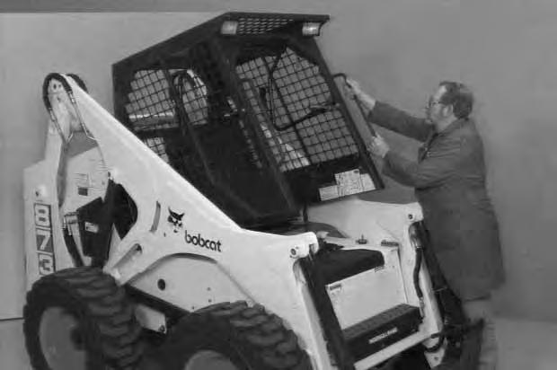
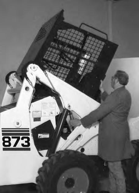
Raising The Operator Cab
7.
Always stop the engine before raising or lowering the cab. Stop the loader on a level surface. Lower the lift arms. Stop the engine. If the lift arms must be up while raising the operator cab, install the lift arm support device. (See LIFT ARM SUPPORT DEVICE Page 40.)
Put jackstands under the rear of the loader frame (Inset) [A]
Mechanical Hand Controls Only: Disconnect the control linkage joint from the bottom hole (work position) and move to the TOP hole on the control handle (both sides) [B]. Both control handles must be in the vertical position so there will be no cab interference with the steering levers when the operator cab is raised or lowered.
Advanced Hand Controls Only: Hold the steering levers forward so that the cab does not hit the levers when raising the cab.
Loosen the nut (both sides) at the front corner of the operator cab [C]


Remove the nut and plate (both sides) [C]
Lift on the grab handle and bottom of the operator cab slowly until the cab latching mechanism engages and the cab is all the way up [A].
OPERATOR CAB (Cont’d)
Lowering The Operator Cab
NOTE:Make sure the seat bar is fully raised or lowered when lowering the cab. Always use the grab handles to lower the cab.
Advanced Hand Controls Only: Hold the steering levers forward so that the cab does not hit the levers when lowering the cab.
Pull down on the bottom of the operator cab until it stops at the latching mechanism.

Release the latching mechanism and pull the cab all the way down [A].
Install the plate and nut (both sides) [B]
Tighten the nuts to 40–50 ft.–lbs. (54–68 Nm) torque.
Use care when raising or lowering the operator cab to prevent damaging the shaft of the lift arm by–pass control.
Mechanical Hand Controls Only: Move the control linkage from the top hole to the BOTTOM hole (work position) on the control handle (both sides) [C]


OPERATOR CAB (Cont’d)

Emergency Exit
The front opening on the operator cab and rear window provide exits.
Rear Window:
Pull on the tag on the top of the rear window to remove the rubber cord [A]
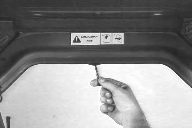
Push the rear window out of the rear of the operator cab. Exit through the rear of the operator cab [B]
Front Door: (If Equipped)
NOTE:When an Operator Cab Enclosure Kit is installed, the window of the front door can be used as an emergency exit. [C]
Pull the plastic loop at the top of the window in the front door to remove the rubber cord [C]
Push the window out with your foot [D]
Exit through the front door.

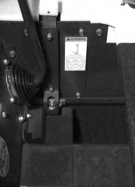
SEAT BAR RESTRAINT SYSTEM (FOOT PEDALS)
The seat bar restraint system has a pivoting, spring assist seat bar with arm rests and has spring loaded interlocks for the lift and tilt control functions.

The operator controls the use of the seat bar. The seat bar in the down position helps to keep the operator in the seat.
The interlocks require the operator to lower the seat bar in order to operate the foot pedal controls.
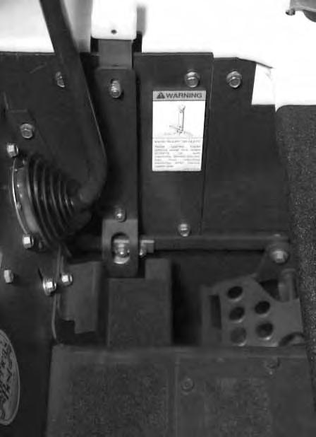
When the seat bar is up, the lift and tilt control functions are locked when returned to the neutral position.
A(Both Sides)
Avoid Injury Or Death
The Seat Bar System must lock the lift and tilt foot pedals or hand controls in neutral when the Seat Bar is up. Service the system if controls do not lock correctly.
W–2263–0597
Inspecting The Seat Bar
Sit in the seat and fasten the seat belt. Engage the parking brake. Pull the seat bar all the way down. Start the engine. Press the green PRESS TO OPERATE Button. Operate each foot pedal to check both the lift and tilt functions. Raise the lift arms until the bucket is about 2 feet (600 mm) off the ground.
Raise the seat bar. Try to move each foot pedal. Pedals must be firmly locked in neutral position. There must be no motion of the lift arms or tilt (bucket) when the pedals are pushed.
Pull the seat bar down, press the green PRESS TO OPERATE Button and lower the lift arms. Operate the lift pedal. While the lift arms are going up,raise the seat bar and the lift arms should stop.
Lower the seat bar, Press the green PRESS TO OPERATE Button, lower the lift arms and put the bucket flat on the ground. Stop the engine. Raise theseat bar and operate the foot pedals to be sure that the pedals are firmly locked in the neutral position. Unbuckle the seat belt.
Maintaining The Seat Bar
8.
See the SERVICE SCHEDULE Page 39 and on the loader for correct service interval.
Clean any debris or dirt from the moving parts [A] & [B]. Inspect the linkage bolts and nuts for tightness. The correct torque is 25–28 ft.–lbs. (34–38 Nm).
If the seat bar system does not function correctly, check for free movement of each linkage part. Check for excessive wear. Adjust pedal control linkage. Replace parts that are worn or damaged. Use only genuine Bobcat loader replacement parts.
Avoid Injury Or Death
Never operate loader without interlock shield 6705474 on both interlocks. Shields prevent foot from unlocking interlocks when leaving loader seat.
W–2158–0594
SEAT BAR RESTRAINT SYSTEM (MECHANICAL HAND CONTROLS)
9.
The seat bar restraint system has a pivoting, spring assist seat bar with arm rests and has spring loaded interlocks for the lift and tilt control functions.
The operator controls the use of the seat bar. The seat bar in the down position helps to keep the operator in the seat.

The interlocks require the operator to lower the seat bar in order to operate the hand controls.
When the seat bar is up, the lift and tilt control functions are locked when returned to the neutral position.
Avoid Injury Or Death
The Seat Bar System must lock the lift and tilt foot pedals or hand controls in neutral when the Seat Bar is up. Service the system if controls do not lock correctly.
W–2263–0597
Avoid Injury Or Death
Never operate loader without interlock shield 6705474 on both interlocks. Shields prevent foot from unlocking interlocks when leaving loader seat.
W–2158–0594
Inspecting The Seat Bar
Sit in the seat and fasten the seat belt. Engage the parking brake. Pull the seat bar all the way down. Press the green PRESS TO OPERATE Button. Start the engine. Operate each hand control to check both the lift and tilt functions. Raise the lift arms until the bucket is about 2 feet (600 mm) off the ground.
Raise the seat bar. Try to move each hand control. The controls must be firmly locked in neutral position. There must be no motion of the lift armsor tilt (bucket) when the controls are pushed.
Pull the seat bar down, press the green PRESS TO OPERATE Button and lower the lift arms. Operate the lift control. While the lift arms are going up, raise the seat bar and the lift arms should stop.
Lower the seat bar, lower the lift arms, press the green PRESS TO OPERATE Button and put the bucket flat on the ground. Stop the engine. Raise the seat bar and operate the hand controls to be sure that the controls are firmly locked in the neutral position. Unbuckle the seat belt.
Maintaining The Seat Bar
See the SERVICE SCHEDULE Page 39 for correct service interval.
Clean any debris or dirt from the moving parts [A] & [B]. Inspect the linkage bolts and nuts for tightness. The correct torque is 25–28 ft.–lbs. (34–38 Nm).
If the seat bar system does not function correctly, check for free movement of each linkage part. Check for excessive wear. Adjust hand control linkage. Replace parts that are worn or damaged. Use only genuine Bobcat loader replacement parts.
SEAT BAR RESTRAINT SYSTEM (ADVANCED HAND CONTROLS) 10.
The seat bar restraint system has a pivoting seat bar (Item 1) [A] with arm rests.
The operator controls the use of the seat bar. The seat bar in the down position helps to keep the operator in the seat.
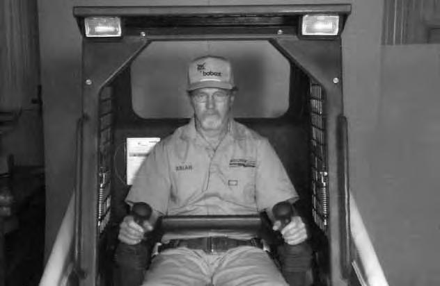
When the seat bar is down and the green PRESS TO OPERATE Button is activated, the lift, tilt, and traction drive functions can be operated.
When the seat bar is up, the lift, tilt, and traction drive functions are deactivated.
Inspecting The Seat Bar
Sit in the operator’s seat. Turn the key ON, lower the seat bar and press the green PRESS TO OPERATE Button. Both lights on the left handle should be ON.
Move each hand control back and forth. You should hear the zip,zip sound of the lift and tilt actuators moving the control valve spools (under the seat).
Raise the seat bar fully. Both lights on the left handle should be OFF.
Move each hand control back and forth. There must be no zip–zip sound of the lift or tilt actuators. If either actuator makes a sound while the seat bar is raised, contact your dealer for service.
Maintaining The Seat Bar
See the SERVICE SCHEDULE Page 39 for correct service interval.
Clean any debris or dirt from the moving parts [B]
If the seat bar system does not function correctly replace parts that are worn or damaged. Use only genuineBobcat replacement parts.
Avoid Injury Or Death
When operating the machine:
• Keep the seat belt fastened snugly.
• The seat bar must be lowered.
• Keep your feet on the foot rests.
W–2179–0694
Before you leave the operator’s seat:
• Lower the lift arms, put the attachment flat on the ground.
• Stop the engine.
• Engage the parking brake.
• Raise seat bar.
• (Advanced Hand Controls) Move the hand controls to the NEUTRAL POSITION to make sure that both lift and tilt functions are deactivated.
The seat bar system must deactivate the lift and tilt control functions when the seat bar is up. Service the system if hand controls do not deactivate.
W–2321–0698
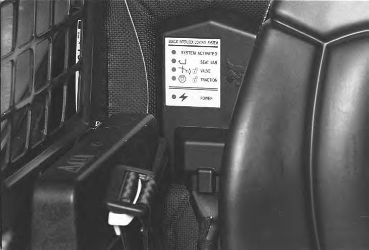
BOBCAT INTERLOCK CONTROL SYSTEM (BICS™) 11.a
Inspecting The BICS™ Controller (Engine STOPPED – Key ON) 13.
1.Sit in the operator’s seat. Turn key ON, lower the seat bar and disengage the parking brake. Press the green PRESS TO OPERATE Button. Four (4) BICS controller lights should be ON (Items 1, 2, 3, & 5) [A]
2.Engage the parking brake and raise the seat bar fully. System Activated (Item 1) [A], seat bar light (Item 2) [A], valve light (Item 3)[A] and traction light (Item 4) [A] should be OFF.
NOTE: If lights on BICS Controller are blinking, see BICS Troubleshooting Chart, Page 77.)
3.Exit the loader and press traction lock override button. Traction light (Item 4) [A] should be ON. Press override button again and traction light (Item 4) [A] should be OFF.
Deactivation Of The Auxiliary Hydraulics System (Engine STOPPED – Key ON) 14.a
4.Sit in the operator’s seat. Lower the Seat Bar. Press the green PRESS TO OPERATE Button. Press the auxiliary hydraulics switch. The auxiliary switchlight will come ON. Raise the Seat Bar. The light should be OFF.
Inspecting The Seat Bar Sensor (Engine RUNNING)
5.Sit in the operator’s seat. Lower the seat bar. Press the green PRESS TO OPERATE button. Engage the parking brake. Fasten the seat belt.
6.Start the engine and operate at low idle. While raising the lift arms, raise the seat bar fully. The lift arms should stop. Repeat using the tilt function.
Inspecting The Traction Lock (Engine RUNNING) 12.
7.Fasten the seat belt, disengage the parking brake, and raise the seat bar fully. Move the steering levers slowly forward and backward. The traction lock should be engaged. Lower the seat bar.
8.Engage the parking brake pedal and move the steering levers slowly forward and backward. The traction lock should be engaged.
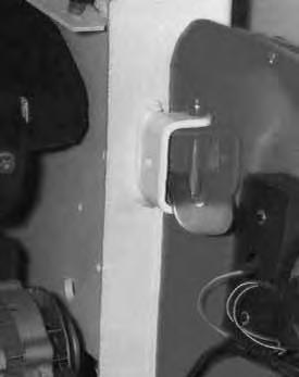
Inspecting The Lift Arm By–Pass Control
9.Raise the lift arms 6 feet (2 m) off the ground. Stop the engine. Turn the Lift Arm By–Pass Control Knob clockwise 1/4 turn. Then pull up and hold the Lift Arm By–Pass Control Knob until the lift arms slowly lower.
Additional Inspection For Loaders With Advanced Hand Controls
10.Sit in the operator’s seat and fasten the Seat Belt. Lower the Seat Bar, start the engine and press the green PRESS TO OPERATE Button.
11.Start the engine and raise the lift arms about 3 feet (1 meter) off the ground.
12.Turn the key OFF and wait for the engine to come to a complete stop.
13.Turn the key ON. Move the left hand control toward the operator. The lift arms should not lower.
14.With the key on and bucket installed, move the right hand control away from the operator. The bucket should not tip forward.
The Bobcat Interlock Control System (BICS™) must deactivate the lift, tilt and traction drive functions. If it does not, contact your dealer for service. DO NOT modify the system.
W–2151–0394
Traction Lock Control System
Inspecting The Traction Lock Control System
1.Sit in the operator’s seat. Turn the key ON, lower the seat bar. Press the green PRESS TO OPERATE Button, and disengage the parking brake. Four (4) of the BICS Controller lights should be ON (Items 1,2,3, and 5) [A]. The Traction light (Item 4) [A] should be OFF.
2.Fasten the Seat Belt, engage the parking brake, start the engine and press the PRESS TO OPERATE Button. Disengage the parking brake and operate at low idle. The Traction light (Item 4) [A] should be ON.
Maintenance
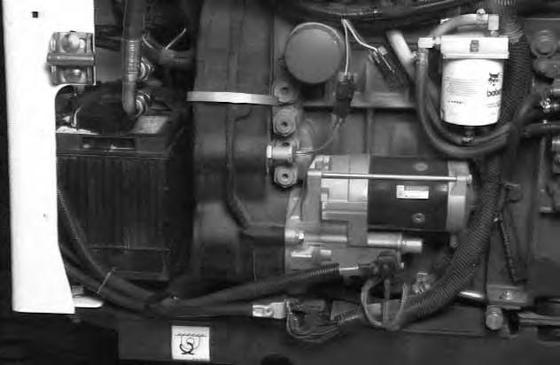
Check the wire connections at the engine speed sensor (Item 1) [B]
NOTE:When the Traction Lock Override Button is activated, the Traction Lock Override Control System will NOT engage the Traction Lock if the engine stops.
Rear Door
Opening And Closing The Rear Door
Avoid Injury Or Death
Never service or adjust the machine when the engine is running unless instructed to do so in the manual.
W–2012–0497
Put your fingers into the slot in the rear door and pull on the latch handle [A]
Pull the rear door open.
Push the door stop up into the hinge (Item 1) [A], then close the rear door.
Keep the rear door closed when operating the machine. Failure to do so could seriously injure a bystander.
Adjusting The Rear Door
The door latch catch (Item 1) [B] can be adjusted side to side for alignment with the door latch mechanism.
The door latch mechanism (Item 2) [B] can be adjusted backward or forward for alignment with the door catch.

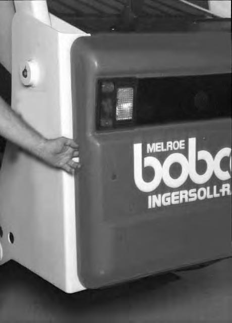
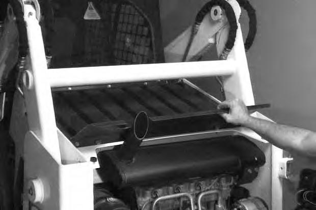
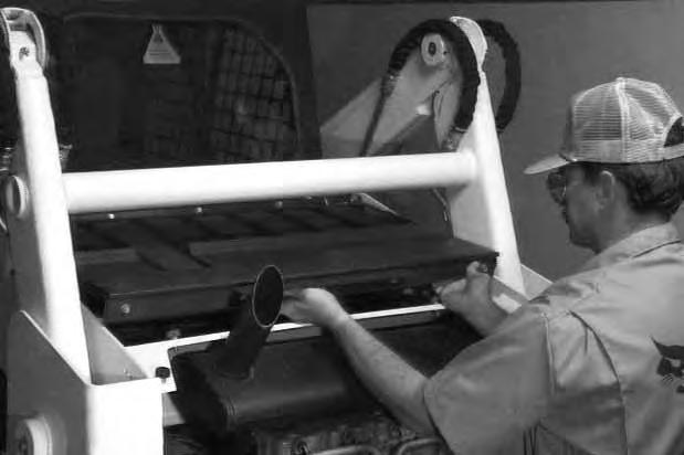
REAR GRILL
3.
Open the rear door.
Lift the panel over the top of the muffler and put it on top of the rear grill [A]
Lift and pull the rear grill and remove it from the loader[B].
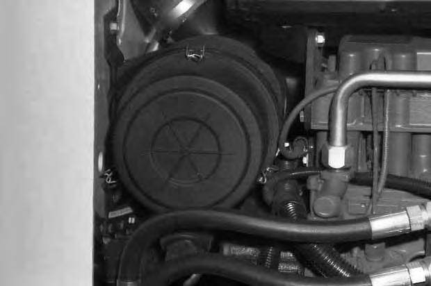
Air Cleaner Service
Without BOSS® – Condition Indicator: Replace the large (outer) filter element only when the red ring shows in the window of the condition indicator (Item 1) [A]
NOTE:Before replacing the filter element, push the button on the condition indicator (Item 1) [A]. Start the engine then stop the engine. If the red ring does not show, do not replace the filter element.

Replace the inner filter every third time the outer filter is replaced or when the red ring still shows in the indicator window after the outer filter has been replaced.
With BOSS®: It is important to change the air filter element only when the service codes (on the optional instrument panel) shows the symbols [AF.2] [B].
AIR CLEANER SERVICE (Cont’d)
Release the three dust cover fasteners (Item 1) [A]
Remove the dust cover.
Remove the large filter element [B]
NOTE:Make sure all sealing surfaces are free of dirt and debris.
Install the new large filter element.
Align the tab on the cover with the slot on the air cleaner housing.
Push dust cover into place and secure with wire fasteners.
Check the air intake hose for damage. Check the air cleaner housing for damage. Check to make sure all connections are tight.
Only replace the inner filter element [C] under the following conditions:
• Replace the inner filter element every third time the outer filter is replaced.
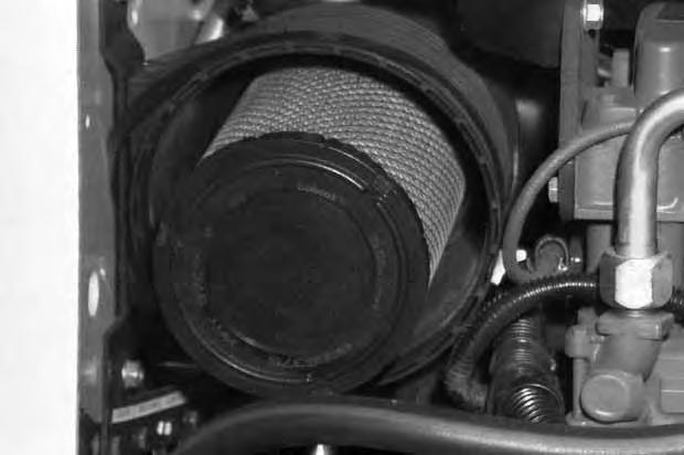
• When the service codes on the instrument panel shows symbol [AF.2] during full engine speed, replace the inner filter element only after the outer filter element has been changed.

Fuel Specifications
Use only clean, high quality diesel fuel, Grade No. 2 or Grade No. 1.
The following is one suggested blending guideline which should prevent fuel gelling problems during cold temperatures:
Temp. F° (C°) No. 2No.1
+15o(9o) 100% 0%
Down to –20o (–29o)50% 50%
Below –20o (29o) 0% 100%
Contact your fuel supplier for local recommendations.
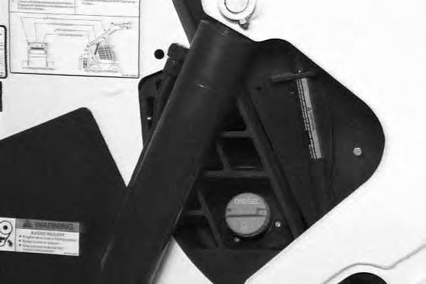
Filling The Fuel Tank
Stop and cool the engine before adding fuel. NO SMOKING! Failure to obey warnings can cause an explosion or fire.
Remove the fuel fill cap (Item 1) [A]
Use a clean, approved safety container to add fuel of the correct specifications. Add fuel only in an area that has free movement of air and no open flames or sparks. NO SMOKING!
Install and tighten the fuel fill cap [A].
Fuel Filter
See the SERVICE SCHEDULE Page 39 for the recommended service interval when to remove the water from the fuel filter.
Loosen the drain (Item 1) [B] at the bottom of the filter element to drain any water from the filter.
See the SERVICE SCHEDULE Page 39 for the recommended service interval when to replace the fuel filter.
Remove the filter element [B]
Clean the area around the filter housing. Put oil on the seal of the new filter element. Install the fuel filter, and hand tighten. Remove the air from the fuel system.
Removing Air From The Fuel System

After replacing the fuel filter element or when the fueltank has run out of fuel, the air must be removed from the fuel system before starting the engine.
Loosen the air vent plug (Item 2) [B] at the top of the fuel filter.
Squeeze the priming bulb (Item 3)[B] until fuel flows from the vent.
Tighten the air vent plug.
Always clean up spilled fuel or oil. Keep heat, flames, sparks or lighted tobacco away from fuel and oil. Failure to use care around combustibles can cause explosion or fire which can result in injury or death.
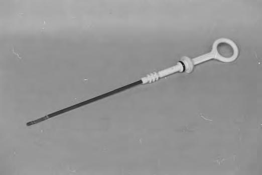
ENGINE LUBRICATION SYSTEM 4. Checking Engine Oil

Check the engine oil level every day before starting the engine for the work shift. Open the rear door and remove the dipstick (Item 1) [A].
Keep the oil level between the marks on the dipstick. Engine oil is also used to provide engine cooling. Check oil level every day for correct engine lubrication and cooling.
Use a good quality motor oil that meets API Service Classification of CD or better (See Oil Chart, right).
Replacing The Oil And Filter
See the SERVICE SCHEDULE Page 39 for the service interval for replacing the engine oil and filter.
Run the engine until it is at operating temperature. Stop the engine. Open the rear door.
Open the rear door. Remove the drain plug (Item 2) [A]. Drain the oil into container and dispose of used oil in an environmentally safe manner. Reinstall the drain plug.
Remove the oil filter (Item 1) [A]
Clean the filter housing surface. Put clean oil on the new oil filter gasket. Install the filter and hand tighten only.
Use only genuine Bobcat filter.
Remove the fill cap (Item 2) [A]
Put 10 qts. (9,5L) of oil in the engine. Start the engine and let it run for several minutes. Stop the engine. Check for leaks and check the oil level.
Remove the dipstick (Item 3) [A]. Check the oil level.
Add oil as needed if it is not at the top mark on the dipstick (Item 1) [B]
Always clean up spilled fuel or oil. Keep heat, flames, sparks or lighted tobacco away from fuel and oil. Failure to use care around combustibles can cause explosion or fire which can result in injury or death.
RECOMMENDED SAE VISCOSITY NUMBER (LUBRICATION OILS FOR DIESEL ENGINE CRANKCASE) SYNTHETIC
TEMPERATURE RANGE ANTICIPATED BEFORE NEXT OIL CHANGE (DIESEL ENGINES MUST USE API CLASSIFICATION CD, CF4, CG4 ) * Can be used ONLY when available with appropriate diesel rating.