34 minute read
MAINTENANCE SAFETY


Instructions are necessary before operating or servicing machine. Read and understand the Operation & Maintenance Manual, Handbook and signs (decals) on machine. Follow warnings and instructions in the manuals when making repairs, adjustments or servicing. Check for correct function after adjustments, repairs or service. Failure to follow instructions can cause injury or death.
W–2003–1298
Safety Alert Symbol:This symbol with a warning statement, means: “Warning, be alert! Your safety is involved!” Carefully read the message that follows.
Correct
Correct
Correct
Never service the Bobcat® Skid Steer Loader without instructions.
Use the correct procedure to lift or lower operator cab.
Cleaning and maintenance are required daily.
Have good ventilation when welding or grinding painted parts. Wear dust mask when grinding painted parts. Toxic dust and gas can be produced. Avoid exhaust fume leaks which can kill without warning. Exhaust system must be tightly sealed.
Disconnecting or loosening any hydraulic tubeline, hose, fitting, component or a part failure can cause lift arms to drop. Do not go under lift arms when raised unless supported by an approved lift arm support device. Replace if damaged.
Never work on loader with lift arms up unless lift arms are held by an approved lift arm support device. Replace if damaged. Never modify equipment or add attachments not approved by Melroe Company.
Wrong Wrong Wrong
Stop, cool and clean engine of flammable materials before checking fluids.
Never service or adjust loader with the engine running unless instructed to do so in the manual. Avoid contact with leaking hydraulic fluid or diesel fuel under pressure. It can penetrate the skin or eyes.
Never fill fuel tank with engine running, while smoking or when near open flame.
Keep body, jewelry and clothing away from moving parts, electrical contacts, hot parts and exhaust.
Wear eye protection to guard from battery acid, compressed springs, fluids under pressure and flying debris when engines are running or tools are used. Use eye protection approved for type of welding. Keep rear door closed except for service. Close and latch door before operating the loader.
Lead–acid batteries produce flammable and explosive gases. Keep arcs, sparks, flames and lighted tobacco away from batteries. Batteries contain acid which burns eyes or skin on contact. Wear protective clothing. If acid contacts body, flush well with water. For eye contact flush well and get immediate medical attention.
Maintenance procedures which are given in the Operation & Maintenance Manual can be performed by the owner/operator without any specific technical training. Maintenance procedures which arenot in the Operation & Maintenance Manual must be performed ONLY BY QUALIFIED BOBCAT SERVICE PERSONNEL. Always use genuine Bobcat replacement parts. The Service Safety Training Course is available from your Bobcat dealer.
742B Bobcat Loader
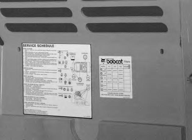
Service Schedule
Maintenance work must be done at regular intervals. Failure to do so will result in excessivewear and early failures. The service schedule is a guide for correct maintenance of the Bobcat loader.
Instructions are necessary before operating or servicing machine. Read Operation Maintenance Manual, Handbook and signs (decals) on machine. Follow warnings and instructions in the manual when making repairs, adjustments or servicing. Check for correct function after adjustments, repairs or service. Failure to follow instructions can cause injury or death.
Engine Oil Check the oil level and add oil as needed.
Engine Air Cleaner Replace the outer filter element only when the red ring shows in the indicator window. Check for leaks and damaged components
Engine Cooling SystemClean debris from shrouds and grills. Check coolant level in the recovery tank and add as needed.
Tires Check for damaged tires and correct air pressure.
Seat Belt and Seat BarCheck the condition of seat belt. Check the seat bar & pedals & Pedal Interlocks pedal interlocks for correct operation .
Safety Signs & SafetyCheck for damage signs (decals) and safety treads Replace
Tread any signs or safety tread that are damaged or worn.
Lift Arm Cyl., Bob–Tach,Add grease to the fittings until the extra grease shows.
Pivot Pin
Operator Cab Check the fastening bolts, washer & nuts. Check the condition of the cab.
Wheel Nuts Check for lose wheel nuts. Tighten to correct torque if loose.
Battery Check the electrolyte level. Check battery cables for corrosion. Check that the battery cables are tight. Check covers.
Hydraulic Fluid, TubelinesCheck fluid level & add as needed. Check for damage, leaks & Hoses & repair or replace as needed.
Alternator & GovernorCheck tension and adjust as needed.
Drive Belts
Chaincase Check the fluid level & add as needed.
Controls & Brake Check operation & adjust as needed.
Engine Oil & Filter Replace the oil & the engine oil filter.
Spark Arrestor MufflerRemove the plug & clean the spark chamber.
Governor Oil Level Check level if low, add oil.
Governor Shaft Grease or oil the shaft.
Seat Bar Grease pivot as needed.
Steering Shaft PivotsGrease two fittings. Add oil to steering shaft.
Hyd./Hydro. Filters Replace filter elements.
U–Joint Grease three (3) fittings with correct grease.
Fuel Filter Replace the filter element.
Hyd. Reservoir BreatherReplace breather cap.
Cap
Chaincase Replace the fluid.
Hydraulic Reservoir Replace the hydraulic fluid.
♦ Check wheel nut torque every 8 hours for the first 24 hours of operation.
• Also replace hydrostatic filter element when the transmission warning light stays on for five (5) minutes after the hydrostatic fluid is at operating temperature. Or every 12 months.
Never work on a machine with the lift arms up unless the lift arms are secured by an approved lift arm support device. Failure to use an approved lift arm support device can allow the lift arms or attachment to fall and cause injury or death.

W–2059–0598
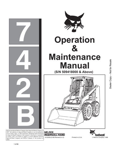
To Engage Lift Arm Support Device
Maintenance and service work can be done with lift arms lowered. If the lift arms are raised, use the following procedure:
Put jackstands under the rear corners of the loader.
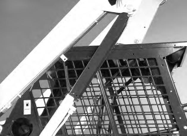
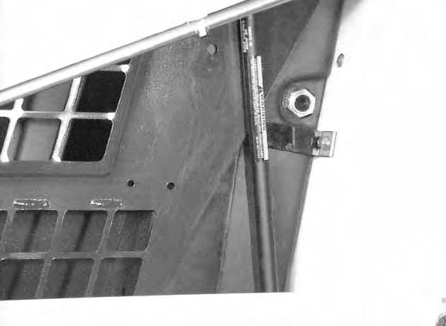
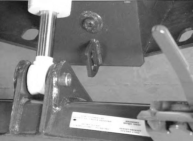
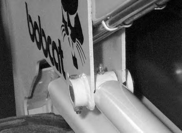
Disconnect the spring from the lift arm support device retaining pin, hold onto the support device and remove the retaining pin [A].
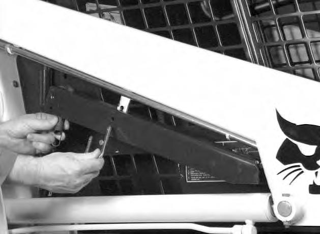
Lower the lift arm support device on top of the lift cylinder. Hook the free end of the spring to the lift arm support device so there will be no interference with the support device engagement [B].
With the operator in the seat, seat belt fastened and seat bar lowered, start the engine.
Raise the lift arms, until the lift arm support device is on the lift cylinder rod [C]
Lower the lift arms slowly until the support device is held between the lift arm and the lift cylinder. Stop the engine. Raise the seat bar and move pedals until both pedals lock.
Install pin into the rear of the lift arm support device below the cylinder rod.
To Disengage Lift Arm Support Device
Remove the pin from the lift arm support device. Connect the spring from the lift arm support device to the bracket below the lift arms [D]
With the operator in the seat, seat belt fastened and seat bar lowered, start the engine.
Raise the lift arms a small amount and the spring will lift the support device off the lift cylinder rod. Lower the lift arms. Stop the engine.
Raise the seat bar and move pedals until both pedals lock.
Disconnect the spring from the bracket.
Raise the support device into storage position and insert pin through lift arm support device and bracket [A]. Connect spring to pin.
Operator Cab
The Bobcat loader has an operator cab (ROPS and FOPS) as standard equipment to protect the operator from rollover and falling objects. Check with your dealer if the operator cab has been damaged.
Never modify operator cab by welding, grinding, drilling holes or adding attachments unless instructed to do so by Melroe Company. Changes to the cab can cause loss of operator protection from rollover and falling objects, and result in injury or death.
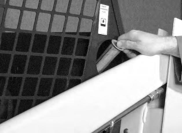
Raising the Operator Cab
Stop the loader on a level surface. Lower the lift arms. If the lift arms must be up while raising the operator cab, install the lift arm support device. (See Page 26.)

Before the cab or the lift arms are raised for service, jackstands must be put under the rear corners of the frame. Failure to use jackstands can allow the machine to tip backward causing injury or death.
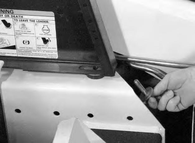
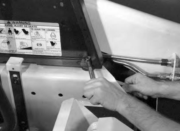
Early Model: Loosen the nut (both sides) at the corner of the operator cab [A].
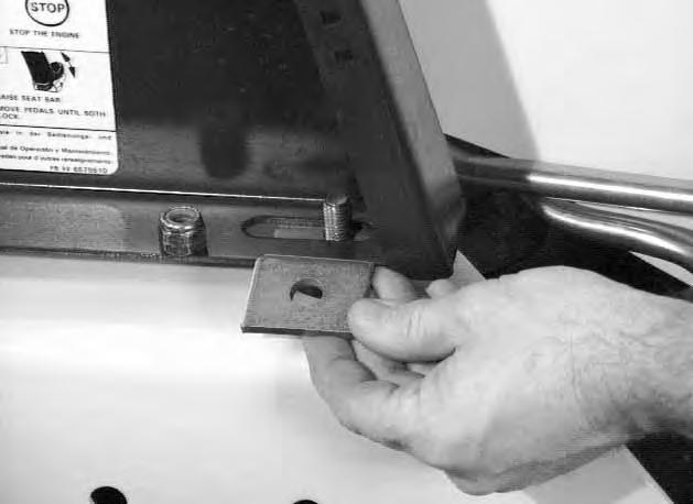
Early Model: Remove the nut and plate (both sides)[B].
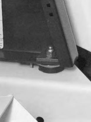
Early Model: Remove the bolt and washer (both sides) [B].

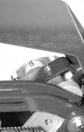
Later Models: Loosen the nut (Item 1) [C] at the corner of the operator cab (both sides).
Later Models: Remove the nut (Item 2) [C] and plate (Item 3) (both sides).
Lift on the grab handle and bottom of the operator cab slowly until the cab latching mechanism engages and the cab is all the way up [D]
OPERATOR CAB (Cont’d)
Lowering the Operator Cab
Pull down on the bottom of the operator cab until it stops at the latching mechanism. Release the latching mechanism and pull the cab all the way down [A].
Install the plate and nut
Tighten the nuts to 40–50 ft.–lbs. (54–68 Nm) torque .
Seat Bar System
The seat bar system has a pivoting seat barwith arm rests and has spring loaded interlocks for the lift and tilt control pedals. The operator controls the use of the seat bar. The seat bar in the down position helps to keep the operator in the seat, also the interlocks require the operator to lower the seat bar in order to operate the foot pedal controls. When the seat bar is up, the lift and tilt pedals are locked when returned to neutral position.
Avoid Injury Or Death
The seat bar system must lock the lift and tilt control pedals in neutral when the seat bar is up. Service the system if pedals do not lock correctly.
W–2105–1285
Sear Bar Inspection
Sit in the seat and fasten the seat belt. Engage the parking brake. Pull the seat bar all the way down. Start the engine. Operate each foot pedal to check both the lift and tilt functions. Raise the lift arms until the bucket is about 2 feet (600 mm) off the ground.
Raise the seat bar. Try to move each foot pedal. Pedals must be firmly locked in neutral position. There must be no motion of the lift arms or tilt (bucket) when the pedals are pushed.
Pull the seat bar down, lower the lift arms and place the bucket flat on the ground. Stop the engine. Raise the seat bar and operate the foot pedals to be sure that the pedals are firmly locked in the neutral position. Unbuckle the seat belt.
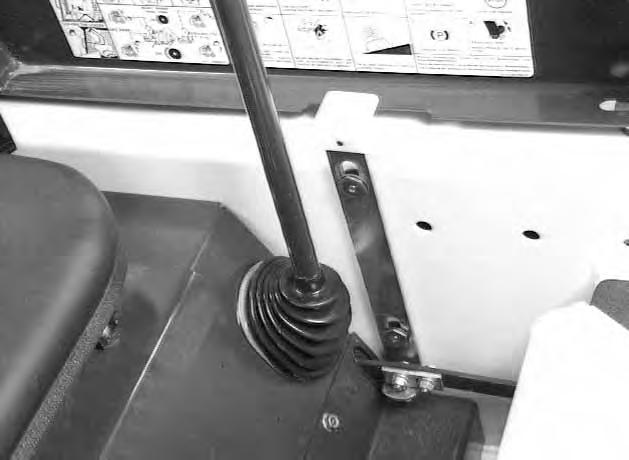
Seat Bar Maintenance
Clean any debris or dirt from the moving parts [B] & [C]. Inspect the linkage bolts and nuts for tightness. The correct torque is 25–28 ft.–lbs. (34–38 Nm).
Use a general purpose grease to lubricate the seat bar pivot points on each side of the cab [B]. If the seat bar system does not function correctly, check for free movement of each linkage part. Check for excessive wear. Adjust pedal control linkage. Replace parts that are worn or damaged. Use only genuine Melroe replacement parts.
Avoid Injury Or Death
Never service or adjust the machine when the engine is running unless instructed to do so in the manual.
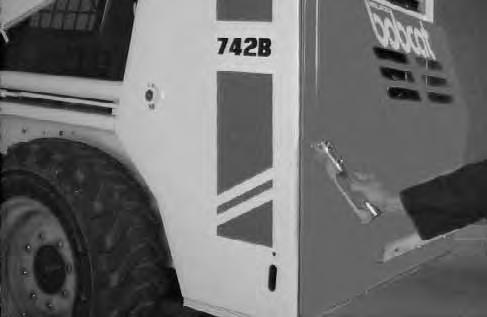
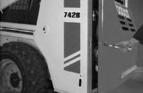
Open the rear door to service the engine. Pull the door latch up and turn to the left to release the door latch [A] Pull the rear door open.
Keep the rear door closed when operating the machine. Failure to do so could seriously injure a bystander.
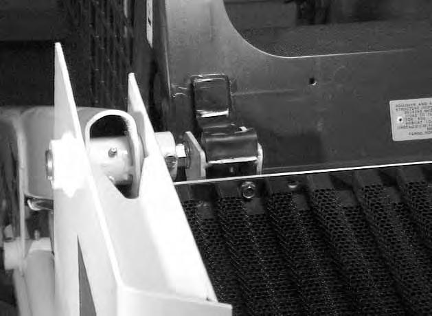
Adjustment
Loosen the set screw (Item 1) [B] .
Loosen the nut (Item 2) [B].
Turn the bolt (Item 3) [B] in or out, until the door makes contact with both the top and bottom of the loader frame (Item 1) [C] when the door lever is in the latchedposition.
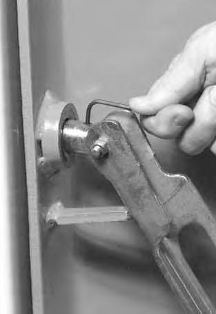
NOTE:It takes approximately 50 lbs. (223 N) of force to push the lever down when the latch is adjusted correctly.
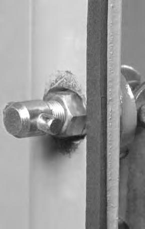
With the set screw up, the flanges at the bolt must be to the side so that the set screw aligns with the flat surface at the end of the bolt.
Tighten the set screw (Item 1) [B]
Tighten the nut (Item 2) to 65–70 ft.–lbs. (88–95 Nm) torque [B] .

Air Cleaner Service
See the Service Schedule Page 25 for the interval to service the air cleaner system or when the red ring shows in the window of the condition indicator.
Service the air cleaner as follows:
NOTE:Before replacing the filter element, push the button on the condition indicator (Inset) and, start the engine [A] . If the red ring does not show, do not replace the filter element.
Loosen the clamp on the dust cup [A]
Remove the dust cup [B]
Remove the wing nut [C]
Remove the element [D].
Check the air cleaner housing for holes or corrosion. Install the new filter element.
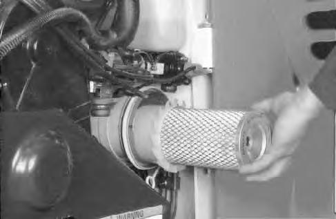
Install the dust cup so the arrow on the cup is up. Tighten the clamp.
All the hoses and clamps must be tight.
Push the button on the condition indicator to remove the red ring.
Fuel System
Fuel Specifications
Use leaded or unleaded gasoline in the engine.
Stop and cool the engine before adding fuel. NO SMOKING! Failure to obey warnings can cause an explosion or fire.
W–2063–0887
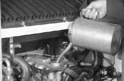
Filling the Fuel Tank
Remove the filler cap [A] .
Use a clean, approved safety container to add fuel.
The key switch must be in the ‘‘OFF’’ position and the engine cool.
Add fuel only in an area that has free movement of air and no open flames or sparks. NO SMOKING [B]
After the fuel has been added install the filler cap and tighten.
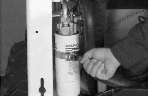
Fuel Filter
See the Service Schedule Page 23 for the interval to service the fuel filter.
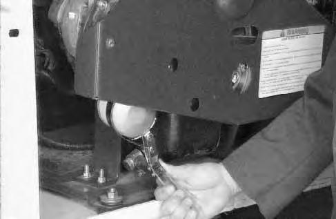
Close the valve on the fuel line (Item 1) [C]
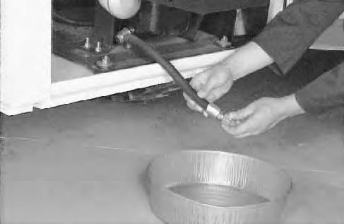
Remove the filter element (Item 1) [D] . Install the new filter element. All connections must be tight.
Open the valve at the fuel tank [C]
Always clean up spilled fuel or oil. Keep heat, flames, sparks or lighted tobacco away from fuel and oil. Failure to use care around combustibles can cause explosion or fire which can result in injury or death.
W–2103–1285
Engine Lubrication System
Check the oil level every day. Stop the engine and remove the dipstick [A] . Keep the oil level between the marks on the dipstick.
Engine Oil and Filter Replacement
See the Service Schedule Page 25 for the service interval for replacing the engine oil.
Use the following procedure to replace the engine oil and filter:

1.Run the engine until it is at operating temperature. Stop the engine.
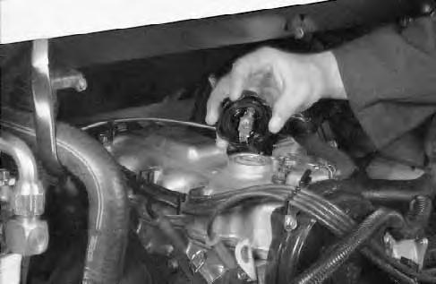
2.Open the rear door. Remove the drain plug and drain oil into a container [B]
3.Remove the oil filter [C]
4.Clean the filter housing surface. Put clean oil on the gasket of the new filter. Install the filter and tighten hand tight.
5.Install the oil plug.
6.Remove the oil filler cap [D]
Use a good quality motor oil that meets API Service Classification of SF or SG (See Oil Chart).
RECOMMENDED SAE VISCOSITY NUMBER (LUBRICATION OILS FOR ENGINE CRANKCASE)
TEMPERATURE RANGE ANTICIPATED BEFORE NEXT OIL CHANGE (GASOLINE: USE API CLASSIFICATION SF or SG)
ENGINE LUBRICATION SYSTEM (Cont’d)
Fill to capacity [A](See Specification Section, Page 65).
Start the engine and let it run or about 5 minutes. Check for leaks at the filer. Check the oil level. Add oil until the level is at the ‘‘FULL’’ mark on the dipstick. Install the oil filler cap.
NOTE: DO NOT overfill the crankcase.
Always clean up spilled fuel or oil. Keep heat, flames, sparks and lighted tobacco away from fuel and oil. Failure to use care around combustibles can cause explosion or fire which can result in injury or death.
W–2103–1285
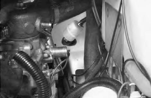
Cooling System
Check the cooling system every day to prevent overheating, loss of performance or engine damage.
Checking the Coolant Level
Open the rear door.
The coolant recovery tank (Item 1) [A] must be at the ‘‘FULL COLD’’ mark when engine is cool.
Add pre–mixed coolant, 50 % water and 50% anti–freeze to the recovery tank if the coolant level is low.
Failure to obey warnings can cause the machine to tip or roll over
• When fluids are under pressure.
• Flying debris or loose material is present.
• Engine is running
• Tools are being used.
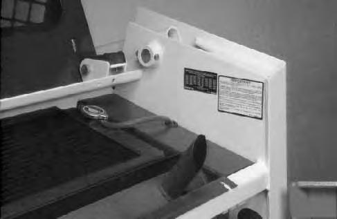
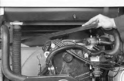
Cleaning the Cooling System
Open the rear door.
Remove the access panels at the blower housing [B].
Remove the rear grill. (See Page 30.)
Use air pressure or water pressure to remove the debris in the area of the radiator and oil cooler [C]
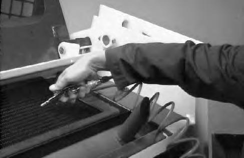
If debris is a problem, check with your dealer about the special debris screens.
Removing Coolant from the Cooling System
Remove the rear grill. (See Page 30.) Remove the radiator cap [D].
COOLING SYSTEM (Cont’d)
Remove the radiator hose [A]
Drain the coolant into a container [B]
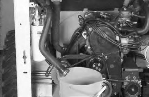
Connect the radiator hose when all the coolant is removed.
Fill the radiator with pre–mixed coolant and install the radiator cap.
Check the radiator cap for correct pressure rating or overheating can result.
Check for leaks in the cooling system. Check for worn or damaged hoses, clamps or radiator. Check for loose or worn water pump belt.
Replace damaged parts immediately to prevent leaksand overheating.
Install the rear grill.
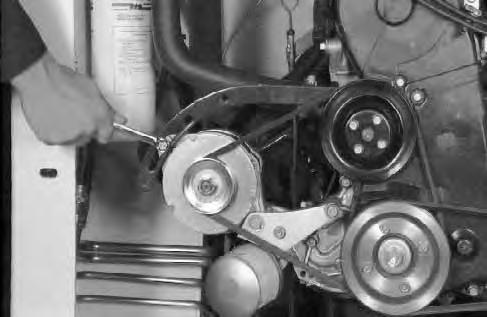
Alternator Belt Adjustment
To adjust the belt tension, use the following procedure:
1.Stop the engine.
2.Remove the belt shield [A].
3.Loosen the bolts that mount the alternator [B]
4.Move the alternator until the belt tension permits 1/4’’ movement at the middle of the beltwith 20 lbs. (9 kg) of force. Tighten the bolts [B]
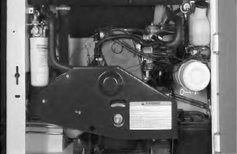
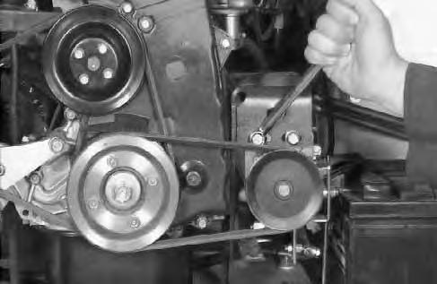
Governor
Governor Belt Adjustment
To adjust the belt tension, use the following procedure:
1.Stop the engine.
2.Remove the belt shield [A]
3.Loosen the bolts that mount the governor [B].
4.Move the governor until the belt tension permits 1/4’’ (6,3 mm) movement at the middle ofthe belt with 20 lbs. (9 kg) of force. Tighten the bolts [B].
5.Install the belt shield before starting the engine.
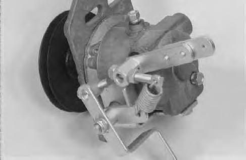

Governor Adjustment
To adjust the governor linkage, use the following procedure:
1.Stop the engine.
2.Loosen the screws (Item 1)[C] on the governor arm.
3.Hold the governor arm in the closed position. Tighten the screws.
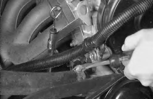
Governor Oil Level
See the Service Schedule Page 23 for the correct service interval to check the governor oil level. Use the following procedure:
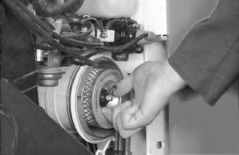
Remove the check plug (Item 1) [D] at the rear of the governor.
If oil flows out the hole, the level is adequate.
If no oil flows out the hole, remove the fill plug (Item 2) at the top of the governor and add SAE 10W–30 or 10W–40 until oil flows from the check plug hole (Item 1)[D] . Install the plug and tighten.
ELECTRICAL SYSTEM Description
The loader has a 12 volt, negative ground alternator charging system.
If the two fuses in the dash panel become damaged, replace them with the same type and size fuses.
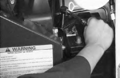
Electrical System Service
The battery cables must be clean and tight. Remove any acid or corrosion from the battery and cables with a baking soda and water solution. Cover the terminals of the battery with Melroe Battery Saver (P/N 886398) to prevent corrosion [A]
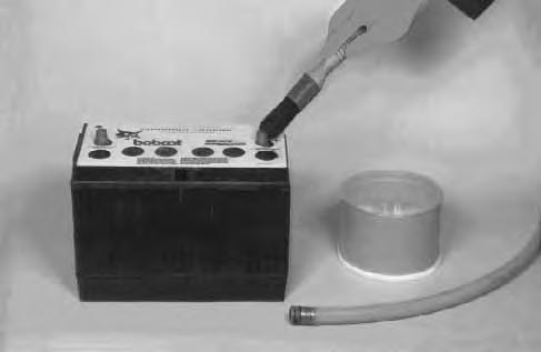
Install the terminal covers.
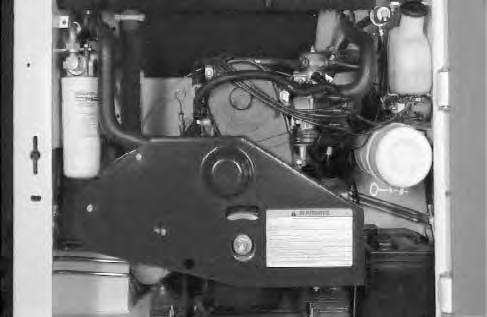
Using A Booster Battery (Jump Starting)
Damage to the alternator can occur if:
• Engine is operated with battery cables disconnected.
• Battery cables are connected when using a fast charger or when welding on the loader. (Remove both cables from the battery.)
• Extra battery cables (booster cables) are connected wrong.
I–2023–1285
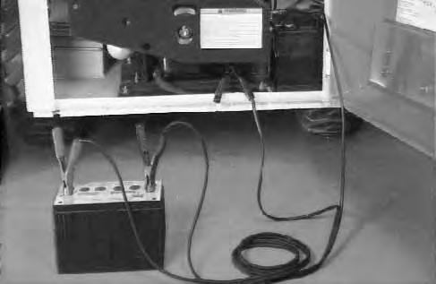
If it is necessary to use an extra battery to start theengine, BE CAREFUL There must be one person in the operator’s seat and one person to connect and disconnect the battery cables.
The ignition must be in the ‘‘OFF’’ position.
The battery must be 12 volt.
Connect the end of the first cable to the positive terminal (+) of the booster battery. Connect the other end of the same cable to the loader battery positive (+) terminal[B].
Connect the end of the second cable to the negative terminal (–) of the booster battery. Connect the other end of second cable to the engine [B]
Keep the cables away from moving parts.
Start the engine.
After the engine has started, remove the ground cable connected to the engine first.
Remove the cable connected to the loader battery.
Batteries contain acid which burns eyes and skin on contact. Wear goggles, protective clothing and rubber gloves to keep acid off body.
In case of acid contact, wash immediately with water. In case of eye contact get prompt medical attention and wash eye with clean, cool water for at least 15 minutes.
If electrolyte is taken internally drink large quantities of water or milk! DO NOT induce vomiting. Get prompt medical attention.
W–2065–1296
Keep arcs, sparks, flames and lighted tobacco away from batteries. When jumping from booster battery make final connection (negative) at engine frame.
Do not jump start or charge a frozen or damaged battery. Warm battery to 60°F. (16°C.) before connecting to a charger. Unplug charger before connecting or disconnecting cables to battery. Never lean over battery while boosting, testing or charging.
Battery gas can explode and cause serious injury.
W–2066–1296
ELECTRICAL SYSTEM (Cont’d)
Battery Removal and Installation
Batteries contain acid which burns eyes and skin on contact. Wear goggles, protective clothing and rubber gloves to keep acid off body.
In case of acid contact, wash immediately with water. In case of eye contact get prompt medical attention and wash eye with clean, cool water for at least 15 minutes.
If electrolyte is taken internally drink large quantities of water or milk! DO NOT induce vomiting. Get prompt medical attention.
W–2065–1296
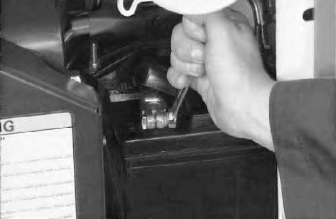
Open the rear door. Disconnect the negative (–) battery cable first
Disconnect the positive (+) battery cable (Item 1) [A].
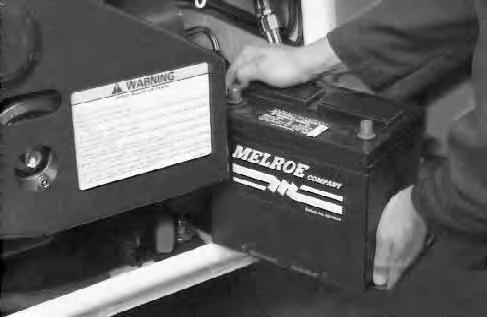
Remove the battery holddown clamp (Item 1) [B]
Remove the battery from the loader [C].
Always clean the terminals and cable ends when installing a new battery [D].
When installing the battery in the loader, do not touch any metal parts with the battery terminal posts.
Connect and tighten the battery cables. Connect the negative (–) cable last to prevent sparks.
HYDRAULIC/HYDROSTATIC SYSTEM
The hydraulic and hydrostatic systems use the same hydraulic fluid reservoir.
The system has an engine driven gear pump that supplies fluid to the control valve, lift and tilt cylinders.
Fluid also goes from the control valve to the hydrostatic transmission pumps to provide charge pressure and cooling.
A–3 filter element is installed on the left side of the engine compartment. This filter is used to clean the fluid for the hydrostatic transmission.
The location of the oil cooler is above the engine. The oil cooler is used for cooling the hydraulic fluid before it returns to the hydrostatic pump.
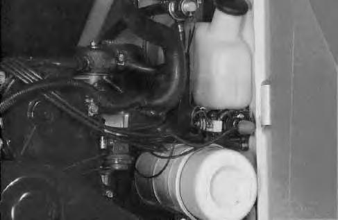
Checking and Adding Fluid
Use only recommended fluid in the hydraulic/hydrostatic system. (See Specifications, on Page 68 for the correct fluid.)
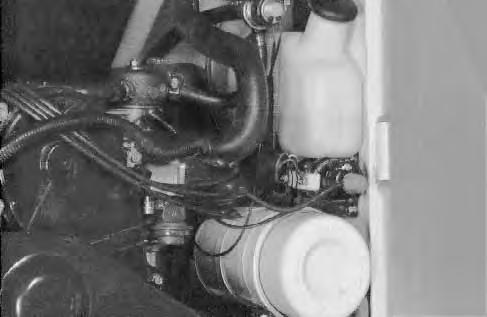
To check the fluid in the reservoir, use the following procedure:
Put the loader on a level surface. Lower the lift arms and lay the attachment flat on the ground. Stop the engine.
Hydraulic fluid must show in the sight glass (Item 1) [A].
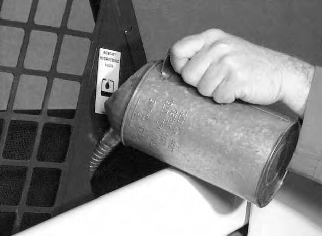
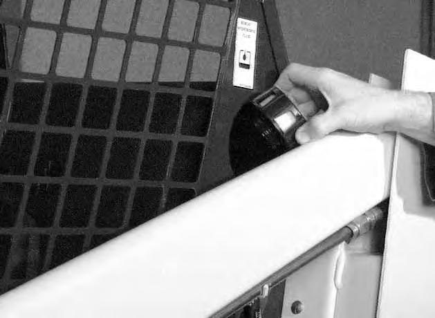
If the fluid is not seen in the sight glass, remove the filler cap from the reservoir [B]

Add fluid to the reservoir until it shows in the sight glass [C]. Replace the filler cap.
HYDRAULIC/HYDROSTATIC SYSTEM (Cont’d)
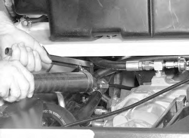
Replacement of the Hydraulic/Hydrostatic Filter Element
See the Service Schedule Page 25 for the correct service interval.
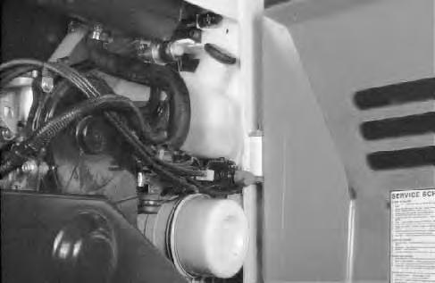
Stop the engine. Open the rear door.
Clean the area around the filter housing.
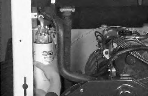
Remove the filter element [A]
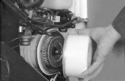
Clean the surface of the filter housing head where the filter element seal contacts the filter housing.
Lubricate the rubber gasket with grease.
Install the filter element and hand tighten only [B]
Operate the loader and check for leaks at the filter. Check fluid level in the reservoir and add as needed.
Removing the Hydraulic Fluid
See the Service Schedule Page 25 for the service interval to replace the fluid. The fluid must also be replaced if it becomes contaminated and after any major repairs.
Remove the filler cap from the reservoir [C].
Remove the screen from the fill pipe [D]
Remove fluid from the hydraulic reservoir.
Wash the screen in clean solvent. Install the screen in the fill pipe.
Remove the filter element and install a new filter element. Add hydraulic/hydrostatic fluid to the reservoir. (See Specifications, Page 58 for the correct fluid.) DO NOT fill above the sight glass.
Operate the loader. Stop the engine and check the fluid level. Add as needed.
Always clean up spilled fuel or oil. Keep heat, flames, sparks or lighted tobacco away from fuel and oil. Failure to use care around combustibles can cause explosion or fire which can result in injury or death.
W–2103–1285
Spark Arrestor Muffler
See the Service Schedule Page 25 for correct service interval. Do not operate the loader with a defective exhaust system.
This loader is factory equipped with a U.S.D.A. Forestry Service approved spark arrestor muffler. It is necessary to do maintenance on this spark arrestor muffler to keep it in working condition. The spark arrestor muffler must be serviced by dumping the spark chamber every 100 hours of operation.
If this machine is operated on flammable forest, brush or grass covered land, it must be equipped with a spark arrestor attached to the exhaust system and maintained in working order. Failure to do so will be in violation of California State Law, Section 4442 PRC.
Make reference to local laws and regulations for spark arrestor requirements.
I–2022–0595
Stop the engine. Open the rear door.
Remove the plug at the bottom ofthe muffler (Item 1) [A]
Stop engine an allow the muffler to cool before cleaning the spark chamber. Wear safety goggles. Failure to obey can cause serious injury.
W–2011–1285
When an engine is running in an enclosed area, fresh air must be added to avoid concentration of exhaust fumes. If the engine is stationary, vent the exhaust outside. Exhaust fumes contain odorless, invisible gases which can kill without warning.
W–2050–1285
Never use machine in atmosphere with explosive dust or gases or where exhaust can contact flammable material. Failure to obey warnings can cause injury or death.
W–2068–1285
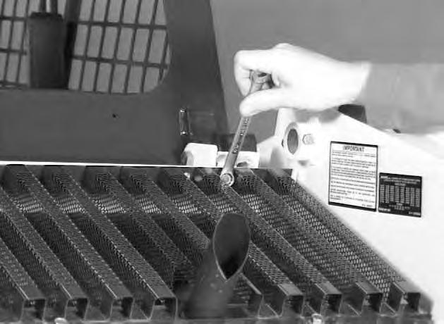
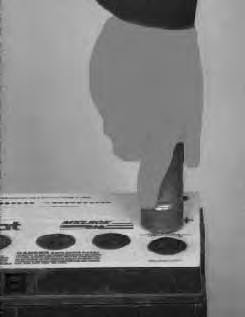
Start the engine.
Wearing safety goggles, have a second person hold a block of wood over the outlet of the muffler (with the engine running) for about 10 seconds.
Stop the engine and install the plug. Close the rear door.
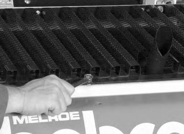
Tire Maintenance
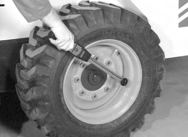
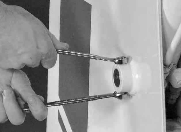
Wheel Nuts
See the Service Schedule Page 25 for the service interval to check the wheel nuts. The correct torque is 105–115 ft.–lbs. (142–156 Nm) [A]
Tire Rotation
Check the tires regularly for wear, damage and pressure (See Specifications, Page 68 for the correct tire pressure).
Rear tires usually wear faster than front tires. To keep tire wear even, move the front tires to the rear and rear tires to the front [B].
It is important to keep the same size tires on each side of the loader to avoid excessive wear. If different sizes are used, each tire will be turning at a different speed and cause excessive wear. The tread bars of all the tires must face the same direction.
Recommended tire pressure must be maintained to avoid excessive tire wear and loss of stability and handling capability. Check for the correct pressure before operating the loader.
Tire Inflation
Tires are to be repaired only by an authorized person using the proper procedures and safety equipment. Tires and rims must always be checked for correct size before mounting. Check rim and tire bead for damage.
The rim flange must be cleaned and free of rust. The tire bead and rim flange must be lubricated with a rubber lubricant before mounting the tire, avoid excess pressure which can rupture the tire and cause serious injury or death. During inflation of the tire, check the tire pressure frequently to avoid over–inflation.
Do not inflate tires above specified pressure. Failure to use correct tire mounting procedure can cause an explosion which can result in injury or death.
W–2078–1285
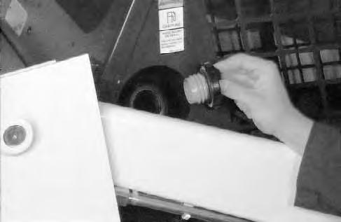
FINAL DRIVE TRANSMISSION (CHAINCASE)
Checking and Adding Oil
The chaincase contains the final drive sprockets and chains and uses the same type of oil as the hydraulic/hydrostatic system (See Specifications Section, Page 68).
To check the chaincase oil level, use the following procedure:
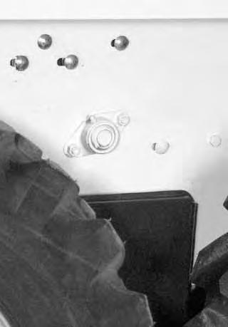
Drive the loader onto a level surface. Stop the engine. Remove the plug (Item 1) at the front of the chaincase housing [A].
.
If oil can be reached with the tipof the your finger through the hole the oil level is correct.
If the level is low, add oil through the check plug hole until the oil flows from the hole. Install and tighten the plug.
Lubrication Of The Bobcat Loader
Lubricate the Bobcat loader as specified in the Service Schedule Page 25 for the best performance of the loader.
Always use a good quality lithium based multi–purpose grease when you lubricate the loader. Apply the lubricant until the extra grease shows.
Lubricate the following locations on the loader:

BOB–TACH
Inspection And Maintenance
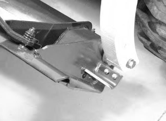
Move the Bob–Tach levers to engage the wedges [A]. The levers and wedges must move freely.
The wedges must extend through the holes in the attachment mounting frame (Item 1) [A]
Bob–Tach wedges must extend through the holes in attachment. Lever(s) must be fully down and locked. Failure to secure wedges can allow attachment to come off and cause injury or death.
W–2102–0497
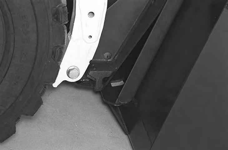
The spring loaded wedge (Item 1) [A] must contact the lower edge of the hole in the attachment(Item 1) [B] and [C].
If the wedge does not contact the lower edge of the hole [B] and [C], the attachment will be loose and can come off the Bob–Tach.
Inspect the mounting frame on the attachment and the Bob–Tach, linkages and wedges for excessive wear or damage [D]. Replace any parts that are damaged, bent, or missing. Keep all fasteners tight.
Look for cracked welds. Contact your Bobcat dealer for repair or replacement parts.
Lubricate the wedges (SeeSERVICE SCHEDULE, Page 21 and LUBRICATION OF THE BOBCAT LOADER, Page 42).
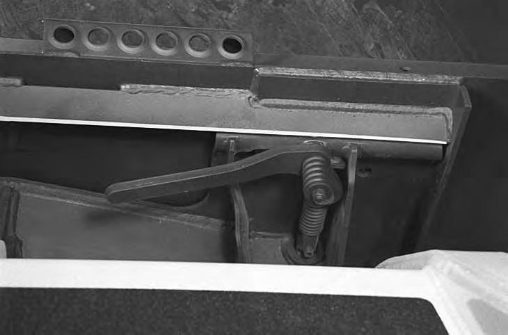
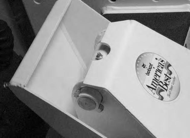
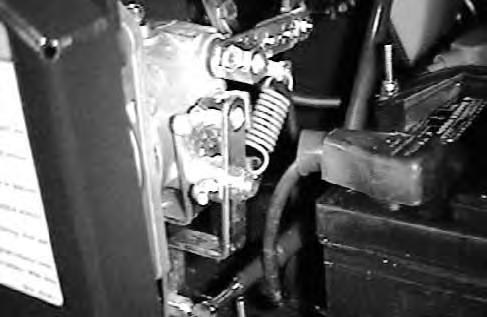
Parking Brake Pedal
NOTE:S/N 18001–18668 must be equipped with shoulder bolts on the rear chaincase cover (See your Bobcat loader dearer). Check the rear chaincase cover bolts for 20–25 ft.–lbs. (27–34 Nm) torque [A].
Adjustment
Turn the nuts to adjust the brake pedal [B].
There must be 3/4’’ (19 mm) of movement under the bottom edge (heel) of the brake pedal.
742B (S/N 18001 – 18133)
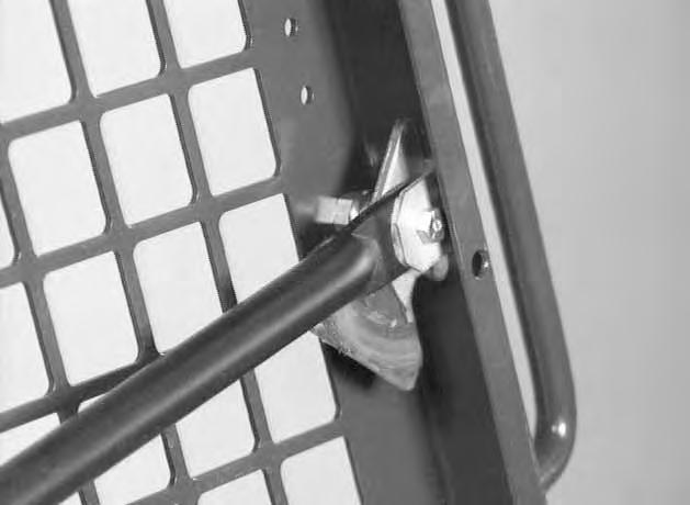
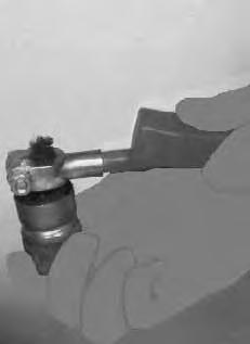
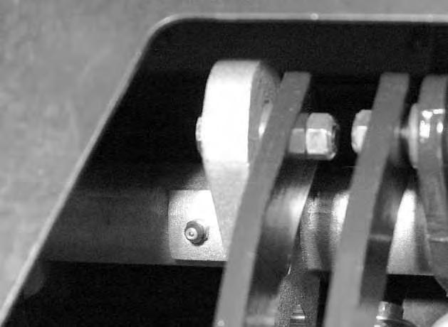
Pivot Pins
All lift arm and cylinder pivots have a large pin held in position with a retainer bolt and lock nut [C].
Check that the lock nuts are tightened to 18–20 ft.–lbs. (24–27 Nm) torque.
P–0201
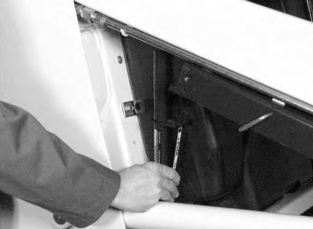
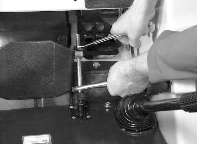
Auxiliary Control Lockbolt
The auxiliary control has a lockbolt (Item 1) that must be removed to use the optional auxiliary hydraulics.
Raise the operator cab (See Page 23).
Remove the nut and bolt (Item 1) [A] at the right hand steering lever.

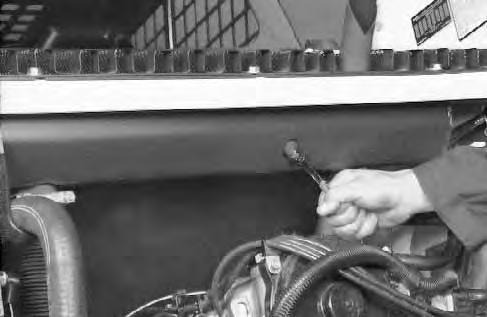
U–JOINT LUBRICATION
See the Service Schedule Page 25 for the service interval when to grease the U–joints.
Raise the operator cab. (See Page 27.)
Use the special U–joint grease (P/N 6599719) to assure correct lubrication for the U–joint. [B].
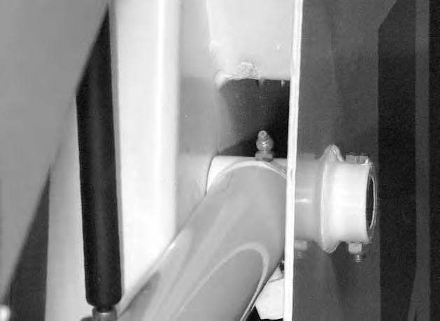
Governor Lubrication
See the Service Schedule Page 25 for the service interval when to grease the governor shaft.
Add grease to the fitting (Item 1) [C]
If the governor is not equipped with a grease fitting, oil the shaft at the same interval.
Troubleshooting
The following information identifies loader problems which can occur most often. Service procedures for correcting loader problems can be found in this manual on the pages indicated. Some procedures are marked ’D/S’ (Dealer Service) and must be performed only qualified Bobcat service personnel.
Instructions are necessary before operating or servicing machine. Read Operation Maintenance Manual, Handbook and signs (decals) on machine. Follow warnings and instructions in the manual when making repairs, adjustments or servicing. Check for correct function after adjustments, repairs or service. Failure to follow instructions can cause injury or death. W–2003–1289
Engine won’t turn over with Battery has low charge. Charge battery and find cause–starter. loss of damage.
Cables loose or dirty. Clean and tighten the battery36 cables.
Damaged starter, solenoid orCheck the starting circuit. D/S wiring. Repair as needed.
Engine turns with starter, but isWrong starting procedure.Use correct starting procedure.9 difficult to start.
No pre–heat Use correct starting procedure9
Engine has little power or runsDirt, water or air in fuel systemClean and repair as needed.D/S rough.
Engine has little power or runsEngine is hot. See ”Engine Overheats”. –rough (Cont’d).
Plugged fuel injectors. Clean or replace. D/S
Restricted exhaust Clean exhaust system 40
Dirty air cleaner. Install new element. 27
Cylinder compression is low.Recondition the engine. D/S
Engine overheats. Restriction in cooling air flow.Check for debris on radiator grill.33
Blower shroud damaged orCheck shroud and repair or–missing. replace as needed.
Engine is overheated. Run at full throttle. –
No drive on both sides. Hydraulic fluid is low. Check fluid level. Add as needed.38
Damaged hydraulic pump.Check condition of pump and D/S replace as needed.
Hydrostatic system is damaged.Check hydrostatic system D/S
No drive on one side. Control linkage is disconnected.Repair linkage. D/S
Hydrostatic system is damaged.Check hydrostatic system andD/S make repair as needed.
Machine pulls to one side.Wrong tire pressure. Check all tires for correct D/S pressure.
Steering linkage out of Check steering linkage and D/S adjustment adjust as needed.
Damaged hydrostatic system.Check system. Repair as needed.D/S
Machine moves when leversSteering linkage out of Adjust steering linkage. D/S are in neutral adjustment.
Servos out of adjustment.Adjust steering D/S
System is overheating. Hydraulic fluid level is lowCheck fluid level and add as38 needed.
Cooling system is dirty. AirClean cooling system. Check33 restricted for debris on radiator grill.
Low charge pressure Check by–pass valve. D/S (transmission light on).
Auxiliary control in detent.Take out of detent. 46
Bobcat is overloaded. Use correct size attachment.D/S
Hydrostatic transmission damage.Check system and make repairD/S
Parking brake will not hold.Out of adjustment. Adjust parking brake. 45
No hydraulic action. No hydraulic fluid. Check fluid level and add as38 needed.
Pedals are disconnected.Check linkage. Repair as –needed.
Relief valve is damaged.Replace the relief valve. D/S
Hydraulic pump is damaged.Check pump. Replace as D/S needed.
Hydraulic fluid is too thick.Let machine warm up.
11
Hydraulic action is rough.Hydraulic fluid level is low.Check fluid level and add as38 needed.
Hydraulic action is slow. Pedal is hitting floor or debrisCheck adjustment. Remove–under pedal. dirt.
Cylinders leak internally.Check condition of cylindersD/S and repair as needed.
Hydraulic pump is damaged.Check pump. Replace as D/S needed.
Control valve is damaged.Check valve and repair as D/S needed.
Hydraulic fluid is too thick.Let machine warm up.
11
Hydraulic cylinders leak fluid.Damage to cylinder rods orRepair cylinders. D/S seals.
Machine Signs Translations
MACHINE SIGNS (Decals)
Machine signs (decals) are an essential part of the loader (See Page vi & vii). This sectin provides French, German and Spanish translations of the machine signs that are in English. The Operator’s Handbook is also available in an comination English, French, German and Spanish edition.
ADVERTENCIA (SPANISH)
Evite Heridas O La Muerte
• Mantenga le puerta cerrada excepto para dar servicio.
• Mantenga el motor limpio y que no tenga material inflamable.
• Mantenga el cuerpo. objetos sueltos y la ropa lejos de los conductores eléctricos, piezas móviles, piezas calientes y del escape.
• No use el cargador en lugares donde hay polvo o gases explosivos o materiales inflamables cerca al escape.
• Todos los gases del escape pueden matar. Ventile siempre el lugar de trabajo.
• No use nunca éter o líquido del arranque en los motores de diesel que tienen tapones encendedores. Use solamente las ayudas para el arranque que sean aprobados por el fabricante del motor.
• Escapes de líquido bajo presión pueden penetrat en la piel y causar heridas graves. Se requiere atención médica inmediata. Use gafas. Use cartón para revisar si hay fugas.
• El ácido de la batería puede causar quemaduras severas, use gafas. Si el ácido hace contacto con los ojos, la piel o la ropa, lávelos bién con agua. Si el contactor fuel en los ojos, lávelo bién y vaya al médico.
• Las baterias producen gas inflammable y explosivo. Mantenga lejos, arcos, chispas, llamas y tabaco encendido.
• Para arranque con batería auxiliar, conecte de último el cable negativo al motor del cargador (nunca la batería). Despues de hacer el arranque con cables, quite peimero la conección negativa del motor.
AVERTISSEMENT (FRENCH)
EVITER LES BLESSURES, VOIRE LA MORT
• Maintenir la porte arrière fermée, sauf pour les entretiens.
• Débarasser le moteur de toute matière inflammable.
• Maintenir le corps, les objets non attachés et les vêtements à l’écart des contacts électriques, des pièces mobiles et brûlantes et de l’échappement.
• Ne pas utiliser la machine dans un endroit chargé de poussières ou de gaz explosifs, et où l’échappement risque de toucher des matériaux inflammables.
• Les gaz d’échappement peuvent être mortels. Toujours aérer.
• Les liquides sous pression peuvent pénétrer au travers de la peau et causer de graves blessures. Consulter immédiatement un médecin Porter des lunettes de sécurité. Utiliser du carton pour repérer les fuites.
• L’acide des batteries provoque de graves brûlures, porter des lunettes de sécurité. S’il entre en contact avec les yeux, la peau ou les vêtements, rincer généreusement à l’eau. Pour les yeux, appeler un médecin.
• Les batteries dégagent des gaz inflammables et explosifs. Tenir les arcs électriques les étincelles, les flammes et las cigarettes allumées à l’écart.
• En cas de démarrage par pontage, effectuer le dernier branchement (Câble négatif) au moteur (jamais à la batterie). Pour débrancher, déconnecter d’abord le câble négatif du moteur.
• Ne jamais utiliser d’éther ou de liquide de démarrage sur un moteur diesel avec des bougies de préchauffage. N’employer que les aides au démarrage approuvées par le fabricant.
PROGRAMA DE SERVICIO (SPANISH)
CADA 10 HORAS
1.Aceite del Motor–Verifique el nivel–no lo llene demasiado (Consulte el Manual del Operario para ver cual fluido recominenda).
2.Filtro del Aire del Motor–(Vacie la tapa recolectora de polvo y cambie el elemento si es necesario).
3.Sistema de Enfriamiento del Motor–Limpiar la basura de las aletas de enfriamiento de la guardera y del enrejado. Verifique en frio el nivel del líquido enfriador, agregue etilenglicol y agua en las cantidades necesarias para obtener una proporción de 50% a 50% de cada uno.
4.Verifique las correas del ventilador y de la bomba para asegurase qu están en buenas condiciones y que la tensión está bién.
5.Brazos de Elecación y Puntos de Pivote del Cilindro – Lubríquelos con grasa de base be litio para uso multiple.
6.Neumáticos – Verifique la persión de aire. FLOTATION – 35 PSI (241 kPa) STANDARD Y CLASIFICACION DE 8 PLIEGOS – 50 PSI (340 kPa), 5.70 x 12 – 40 PSI (275 kPa). Verifique que no tengan cortadas.
7.Sistema de Aire del Motor – Verifique que no haya escapes ni componentes dañados.
8.En General – Verifique que no haya piezas ni sueltas ni rotas, qu no estén dañados ni el cinturón de seguridad ni la cabina deloperador. Verifique tembién el funcionamiento de los instrumentos, que no haya tuercas sueltas en las quedas, escapes de aceite, etc.
9.Filtro del Combustible – Purgue el agua atrapada (solamente para diesel).
CADA 50 HORAS
1.Aceite del Motor – Drenarlo mientras está caliente y cambiar el filtro (en las cargadoras 440 solamentese cambia el aceite cada 25 horas). consulte el Manual del Operador para ver cual fluído recomendado.
2.Fluido Hidráulico – Verifique el nivel del fluído Consulte el Manual del Operador para ver vual fluído recomendado.
3.Caja de la Cadena – Verifique el nivel del fluído. Consulte el Manual del Operador para ver cual fluído recomendado.
4.Batería – Verifique su condición.
5.Controles y Frenos – Verifique el funcionamiento Hacer ajustes si es necesario.
Cada 100 Horas
1.Sistema de Encendido – Verificar las bujias, lo s platinos y la sincronización–cambie las pieza s defectuosas (solamente para gasolina).
2.Silenciador con Amortiguador de Chispas – Vasie la cámara de chispas.
3.Sistema Hidráulico – Cambie el filtro – modelos 440 , 540.
Cada 250 Horas
1.Sistema Hydraulico – Cambie el filtro en el mode l 843.
2.Filttro Final del Combustible – Reemplace e l elemento del filtro.
3.Linea Motriz – Engrase la uniones universales co n una grasa aprobada según la recomendación del Manual de Servicio.
4.Engrase el pivote de la barra del asiento en cuant o sea necesario.
CADA 500 HORAS
1.Sistema Hidráulico – Cambie el filtro de brone si está equipado con este.
2.Filtro Primario del Combustible – Limpie el cubo de sedimento.
3.Reemplace la tapa del respiradero del depósito hidráulico.
CADA 1000 HORAS
1.Depósito Hidráulico–Drenar el fluído y reemplazarlo. Consulte el Manual del Operador para ver cual fluído recomendados.
2.Caja de la Cadena–Drene el fluído y reemplazarlo. Consulte el Manual del Operador para ver cual fluído recomendado.
FILTRO DEL HIDROSTATICO (Modelos 640, 740 y 843)
1.Cambie el filtro cuando se enciendo la luz de aviso del hidrostático. Consulte el Manual del Operador.
PROGRAMME D’ENTRETIEN (FRENCH)
TOUTES LES 10 HEURES
1.Huile de moteur–Vérifier le niveau – ne pasremplir à rasbord (conseiller le manuel d’utilisation pour le fluide recommandé).
2.Filtre à air du moteur (vider la capsule à poussiere changer l’élément si nécessaire).
3.Système de refroidissement du moteur – nettoyer les débris de ailettes de refroidissement, coucliers et grilles. – Vérifier le niveau de température de liquide de refroidissement, ajouter 50–50 d’éthylène glycolet eau autant que nécessaire.
4.Vérifier la condition et la tension du ventilateur et des courroies de transmission de la pompe.
5.Levier du chargeur et les points de pivot du cylindre – graisser avec une huile multi–usage à base de lithium.
6.Pneus – vérifier le gonflement: FLOTATION – 35 PSI (241 kPa), STANDARD et 8 PLY – 50 PSI (340 kPa), 5.70 x 12 – 40 PSI (275 kPa); vérifierl’état des pneus (entailles).
7.Système d’aération du moteur – contrôlerles fuites et les éléments abimés.
8.Conseils géneraus: vérifier les pièces abimées ou ayant du jeu, centinure de sécurité abimée et cabine de l’utilisateur, instrument de commande, écrous devissés des roues, fuites d’huile, etc.
9.Filtre du carburante – retirer l’eau qui s’y trouve (diesel seulement).
TOUTES LES 50 HEURES
1.Huile de moteur – vider chaud et changer le filtre (huile de remplacement seulement, toutes les 25 heures pour chargeur 440). Voir le manual d’utilisation en ce qui concerne l’huile recommendée.
2.Fluide hydraulique – vérifier le niveau du fluide. Voir le manuel d’utilisation pour le fluide recommendé.
3.Boíte à chaines – vérifier le niveau du fluide. Consulter le manuel d’utilisation en ce qui concerne le fluide recommendé.
4.Batterie – vérifier l’etat.
5.commandes et freins – vérifier l’etat de marche, régler si nécessaire.
TOUTES LES 100 HEURES
1.Système d’allumage – vérifier les bougies régler l’allumage, remplaer les pièces défectueuses (essence seulement).
2.Pot d’echappement – vider la chambre à étincelles.
3. 440 et 540).
TOUTES LES 250 HEURES
1.Système hydraulique – changer le filtre sur le 843.
2.Dernier filtre à essence – remplacer la pièce du filtre
3.Arber de transmission – graisser le joint U avec u n lubrifiant approivé par le manuel.
4.Graisser le pivot du siège autant que nécesaire.
TOUTES LES 500 HEURES
1.Système hydraulique – remplacer le filtre bronze sile système en est équipé.
2.Premier filtre à essence – nettoyer le récipiente à seidments.
3.Remplacer le bouchon – filtre du réservo ir hydraulique.
TOUTES LES 1000 HEURES
1.Réservoir hydraulique – vider le fluide et le remplace r. Voir manuel d’utilisation pour le fluide recommendé
2.Boîte à chaînes – vider le fluide et le remplacer pa r celui conseillé par le manual d’utilisation.
FILTRE HYDROSTATIQUE (pour les 640, 740 et 843)
1.Changer le filtre quand le voyant lumineux relatif a u système hydrostatique s’allume. Consulter le manue l d’utilisation pour plus amples informations.
ADVERTENCIA (SPANISH)
EVITE HERIDAS O LA MUERTE
NO USE NUNCA EL CARGADOR SIN LEER LAS INSTRUCCIONES.
LEA EL MANUAL DEL OPERATIO, EL MANUAL DE SERVICIO Y LA GIA DEL OPERARIO.
NO VIAJE O DE LA VUELTA CON LOS BRAZOS DE ELEVACION ARRIBA.
CARGUE, DESCARGUE Y DE LA VUELTA ESTANDO EN UN SITIO PLANO Y NIVELADO.
NO EXCEDA LA CAPACIDAD NOMINAL DE FUNCIONAMIENTO (VEA EL AVISO EN EL CARGADOR).
USE LA BARRA DEL ASIENTO.
ASEGURESE BIEN EL CINTURON DE SEGURIDAD.
NUNCA MODIFIQUE EL EQUIPO NI USE ADITAMENTOS QUE NO ESTEN APROBADOS POR LA COMPAÑIA MELROE.
MANTENGA LOS PIES EN LOS PEDALES.
EN LA PENDIENTES, MANTENGA EL EXTREMO PESADO DE CARGADOR EN POSICION ASCENDENTE.
ANTES DE BAJARSE DEL CARGADOR
1.BAJE LOS BRAZOS DE ELEVACION. COLOQUE EL ADITAMENTO BEIN EN EL SUELO.
2.PARE EL MOTOR.
3.PONGA EL FRENO.
4.LEVANTE LA BARRA DEL ASIENTO. MUEVA LOS PEDALES HASTA QUE AMBOS SE TRABEN.
ATTENTION (FRENCH)
EVITER LES BLESSURES OU LA MORT
NE JAMAIS SE SERVIR DE LA CHARGEUSE SANS INSTRUCTIONS.
LIRE LE MANUEL DE L’OPERATEUR EL D’ENTRETIEN AINSI QUE LE GUIDE D’UTILISATION.
NE PAS SE DEPLACER NI VIRER AVEC LE BRAS RELEVES.
CHARGER, DECHARGER ET VIRER SUR UN SOL PLAT ET HORIZONTAL.
NE PAS DEPASSER LE CAPACITE NOMINALE (CONSULTER L’AUTOCOLLANT APPOSE SUR LA CARGEUSE).
UTILISER L’ARCEAU DE SECURITE. ATTACHER SOIGNEUSEMENT LA CEINTURE DE SECURITE.
NE JAMAIS MODIFIER L’EQUIPEMENT NI SE SERVIR D’ACCESSOIRES QUE NE SONT PAS APPROUVES PAR MELROE COMPANY.
MAINTENIR LES PIEDS SUR LES PEDALES.
DANS LES PENTES, TOUJOURS MAINTENIR LA PARTIE LA PLUS LOURDE DE LA CHARGEUSE VERS LE HAUT.
POUR QUITTER LA CHARGEUSE:
1.ABAISSER LES BRAS DE LEVAGE. POSER L’EQUIPEMENT A PLATE SUR LE SOL.
2.ARRETER LE MOTEUR.
3.ENCLENCHER LE FREIN DE STATIONNEMENT.
4.RELEVER L’ARCEAU DE SECURITE. DEPLACER LES PEDALES JUSQU’A CE QU’ELLES SOIENTE TOUTES DEUX VERROILLEES.
ADVERTENCIA (SPANISH)
EVITE HERIDAS O LA MUERTE
LLEVE LA CARGA EN POSICION BAJA
EL NO OBEDECER ESTA ADVERTENCIA PUEDE CAUSAR LADEAMIENTO O VUELCOS O PERDIDAD DE LA CARGA Y DE LA VISIBILIDAD.
AVERTISSEMENT (FRENCH)
EVITER DES BLESSURES OU LA MORT
TENIR LA CHARGE VERS LE BAS.
LE NON RESPECT PEUT ENTRAINER UN BASCULEMENT OU UN RENVERSEMENT DE LA MACHINE, UNE PERTE DE LA CHARGE OU DE VISIBILITE.
PELIGRO (SPANISH)
EVITE LA MUERTE
• MANTENGASE RETIRADO DE ESTA AREA CUANDO LOS BRAZOS DE ELEVACION ESTAN ELEVADOS, A MENOS QUE ESTEN TRABADOS POW EL TOPE.
• EL MOVER EL PIE DEL PEDAL O FALLA DE UNA PIEZA PUEDEN CAUSAR LA CAIDA DE LOSBRAZOS DE ELEVACION.
DANGER (FRENCH)
EVITER LA MORT
• EVITER CETTER ZONE LORSQUE LES BRAS DE LEVAGE RELEVÉS NE SONT PAS ASSURÉS PAR DES ARRETS DE BRAS DE LEVAGE.
• UNE PEDALE ACTIONNÉE OU UNE PICE DEFECTUEUSE. PEUT PROVOQUER L’ABAISSEMENT DES BRAS DE LEVAGE.
ADVERTENCIA (SPANISH)
EL CILINDRO CONTIENE GAS BAJO ALTA PRESION. EL ABNRIR EL CILINDRO PUEDE SOLTAR LA VARILLA Y CAUSAR HERIDAS O LA MUERTE.
AVERTISSEMENT (FRENCH)
LES VERINS RENFERMENT UN GAZ SOUS PRESSION. NE JAMAIS OUVRIR UN VERIN CAR LA TIGE RISQUE DE S’ECHAPPER BRUTALEMENT ET DE CAUSER DES BLESSURES OU MEME LA MORT.
PELIGRO (SPANISH)
EVITE LA MUERTE
• EL FORZAR EL IMPLEMENTO CONTRA EL SUELO HACE QUE LA RUEDDAS DELANTERAS SE ELEVEN.
• NUNCA SE META DEBAJO NI ALCANCE NADA DEBAJO DE LOS BRAZOS DE ELEVACION O DEL CILINDRO DE ELEVACION SIN QUE ESTE INSLADO UN TOPE APROBADO EN LOS BRAZOS DE ELEVACION.
DANGER (FRENCH)
EVITER LA MORT
• L’ACCESSOIRE PEUT ETRE APPUYE CONTRE LE SOL ET SOULEVER LES ROUES AVANT.
• NE JAMAIS ALLER SOUS NI METTRE LES MAINS SOUS LES BRAS OU LE VERIN DE LEVAGE SANS QU’UN ARRET DE BRAS DE LEVAGE APPROUVE SOIT INSTALLE.
IMPORTANTE (SPANISH)
ESTA MAQUINA ESTA EQUIPADA POR LA FABRICA CON UN AMORTIGUADOR DE CHISPAS DEL SILENCIADOR, APROBADO POR EL SERVICIO DE SILVICULTURA DEL U.S.D.A. (DEPARTMENTO DE AGRICULTURA DE LOS ESTADOS UNIDOS).
ES NECESARIO LIMPIAR ESTE AMORTIGUADOR DE CHISPAS DEL SILENCIADOR PARA MANTENERLO EN BUEN ESTADO. HAY QUE DARLE SERVICIO AL AMORTIGUADOR, VACIANDO LA CAMARA DE CHISPAS CADA 100 HORAS DE FUNCIONAMIENTO.
SI ESTA MAQUINA ESTA DESTINADA PARA TRABAJAR EN BOSQUES, MATORRALES O EN PASTOS QUE PUEDAN INCENDIARSE, ENTONCES TIENE QUE ESTAR EQUIPADA CON UN AMORTIGUADOR DE CHISPAS EN EL SISTEMA DEL ESCAPE Y TIENE QUE MANTENERSE EN PERFECTAS CONDICIONES DE TRABAJO. ES NO HACER ESTO CONSTITUYE UNA INFRACCION DE LA LEY ESTATAL DE CALIFORNIA, SECCION 4442, PRC.
REFIERASE A LAS LEYES Y REGULACIONES LOCALES EN CUANTO A LOS REQUISITOS DEL AMORTIGUADOR DE CHISPAS.
IMPORTANT (FRENCH)
CETTE CHARGEUSE EST EQUIPPEE A LA SORTIE DE L’USINE D’UN SILENCIEUX PARA–ETINCELLES APPROUVE PAR LE SERVICE DES EAUX ET FORETS DES ETATS–UNIS.
IL EST INDISPENSABLE D’EFFECTUER UN ENTRETIEN REGULIER DE CE PARE–ETINCELLES AFIN DE LE GARDER EN BON ETAT DE MARCHE. L’ENTRETIEN CONSISTE A VIDER LA CHAMBRE A ETINCELLES TOUTES LES 100 HEURES DE MARCHE.
SI CET ENGIN EST UTILISE SUR UN TERRAIN COUVERT D’ARBRES, DE BROUSSAILLES, OU D’HERBAGES INFLAMMABLES, IL FAUT INSTALLER LE PARE–ETINCELLES ET LE GARDER EN BON ETAT DE MARCHE.
CONSULTER LES REGLEMENTATIONS LOCALES APPLICABLES.
• Dimensions are given for loader equipped with standard tires and dirt bucket. Dimensions may vary with other types. All dimensions are shown in inches. Respective metric dimensions are given in millimeters enclosed by parentheses.
• Where applicable, specifications conform to SAE standards and are subject to change without notice.
This loader was designed without counterweights or ballasts. Changes of structure or weight distribution of the loader can cause changes in control and steering response and can cause failure of the loader parts.
Direction & speed controlled by two hand levers.
Lift & Tilt Function: Controlled by separate foot pedals.
Front Auxiliary Function: Controlled by the right steering lever.
Hand lever throttle & key–type starter switch;
Mechanical disc, foot operated pedal leaded
LOADER SPECIFICATIONS (Cont’d)
Hydraulic System
Hydraulic
2250–2400 PSI (15514–16548 kPa)
Replaceable #3 micron paper element in charge line
3–spool, open center type, W/float detent on lift, detent on auxiliary
SAE standard tubes, hoses & fittings
Bobcat Fluid (P/N 6563328). If fluid is not available use 10W–30 or 10W–40 Class SE Motor Oil for temperatures above 0 F (–18 C) & 5W–30 for temperatures below 0 F (–18 C)