7 minute read
OPERATING INSTRUCTIONS


INSTRUMENT PANEL
The instrument panel has the following instruments [A].
1.LIGHT SWITCH (OPT.) – Controls the work and travel lights.
2.I GNITION SWITCH – For starting, stopping and ‘‘pre–heating’’ the engine.
3.FUSE (ACCESSORIES) – To protect the electrical system from overload.
4.FUSE (IGNITION) – To protect the electrical system from overload.
5.HOURMETER – Records the total operating hours of the loader.
6.FUEL GAUGE – Shows the amount of fuel in the fuel tank.
7.ENGINE TEMPERATURE GAUGE – Shows the engine coolant temperature.
8.ENGINE WARNING LIGHT – Engine oil pressure is low. Stop the engine if the light comes ‘‘ON’’.
9.TRANSMISSION WARNING LIGHT – Low transmission charge pressure, hydraulic filter needs replacement or high fluid temperature. Stop the engine if the light comes ‘‘ON’’.
10.VOLTMETER – Shows the condition of the battery and the rate of charge.
Throttle Control
The throttle control is at the rightside of the operator seat [B].
Engine speed is controlled by moving thethrottle forward to increase the engine RPM and backward to decrease the engine RPM.
Parking Brake
Lock the parking brake by pushing down on the top (toe) of the pedal [A].
To release the parking brake, push down on the bottom (heel) of the pedal [B].
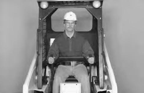
Avoid Injury Or Death
When operating the machine:
• Keep the seat belt fastened snugly.
• The seat bar must be lowered.
• Keep your feet on the pedal controls.
W–2046–0595
The steering levers (Item 1) are on the right and left side in front of the seat [A]
For safe control of the loader always move the levers slowly and smoothly. Only a small movement is necessary to move the loader.
The steering levers control forward and reverse travel of the loader [B].
FORWARD TRAVEL : Push both levers forward.
REVERSE TRAVEL : Pull both levers backward.
NORMAL TURNING: Move one lever farther forward than the other.
FAST TURNING: Push one lever forward and pull the other lever backward.
For slow travel speed, push the levers forward only a small amount.
To increase travel speed, push the levers farther forward. For maximum pushing force, push the levers forward only a small amount with the engine at full RPM.
Backward
Left Turn
Right Turn
Fast Turnfast Turn
Hydraulic Controls
Foot Pedals
Keep both feet on pedals while operating machine. Failure to do so can cause serious injury.
W–2002–1285
Put your feet on the pedals and KEEP THEM THEREany time you operate the loader.
Two foot pedals (Item 1) control the hydraulic cylinders for the tilt and lift function [A]
Lift Arm Operation
The left pedal controls the lift arms. Push on the bottom (heel) (Item 2) of the pedal to raise the lift arms [A]
Push on the top (toe) (Item 3) of the pedal to lower the lift arms [A]. Use the ’’Float’’ position of the lift arms to level loose material while driving backward.
The optional bucket position valve, will keep the bucket at a level position when the lift arms are being raised.
Tilt Operation (Bucket)
The right pedal controls the action of thebucket. Push the top (toe) (Item 4) of the pedal to tilt the bucket forward [A]
Push the bottom (heel) (Item 5) of the pedal to tilt the bucket backward [A].
HYDRAULIC CONTROLS (Cont’d)
Auxiliary Hydraulics Operation (Optional)
The right steering lever is also the control lever for the front auxiliary hydraulics [A]
Move the right steering lever to the left or to the right to activate the auxiliary hydraulics and operate an attachment (Example: To open or close grapple teeth). Move the lever in the opposite direction to reverse the action of the attachment [B].
Move the steering lever all the way to the right (Item 1) to put the control valve into the ‘‘detent’’ position for a constant flow of hydraulic fluid under pressureto the quick couplers [B].
NOTE:See Page 45 to remove auxiliary control lockbolt.
Daily Inspection
The loader must be in good operating condition [A].
Check the following items:
* Engine Oil
* Hydraulic/Hydrostatic Fluid
* Air Cleaner Condition Indicator
* Engine Cooling System *
* Operator Cab, Seat Belt, Seat Bar & Pedal Interlocks
* Lift Arms & Cylinder Pivot Pins
* Tires & Tire Pressure
* Any Loose or Broken Parts
* Safety Tread & Safety Signs
Follow the maintenance requirements on the Service Schedule Decal, located inside the rear door [B]
Instructions are necessary before operating or servicing machine. Read and understand the Operation & Maintenance Manual, Handbook and signs (decals) on machine. Follow warnings and instructions in the manuals when making repairs, adjustments or servicing. Check for correct function after adjustments, repairs or service. Failure to follow instructions can cause injury or death.
W–2003–1298
Seat Bar Restraint System
The seat bar restraint system has a pivoting seat bar (Item 1) with arm rests and has spring loaded interlocks for the lift and tilt control pedals. Theoperator controls the use of the seat bar. The seat bar in the down position helps to keep the operator in the seat. The interlocks require the operator to lower the seat bar in order to operate the foot pedal controls. When the seat bar is up, the lift and tilt control pedals are locked when returned to the neutral position [A]
Avoid Injury Or Death
When operating the machine:
• Keep the seat belt fastened snugly.
• The seat bar must be lowered.
• Keep your feet on the pedal controls.
W–2046–0592
The spring loaded interlocks (Item 1) control the locking and unlocking functions of the control pedals [A]
The interlocks (Item 1) require the operator to lower the seat bar (Item 2) which allows the operator to move the foot pedals to control the lift and tilt functions [B].
When the seat bar is lowered, it pushes the interlock (Item 1) down on both sides, releasing the pedal linkages (Item 3) from the interlocks [B].
The pedals now pivot in both directions when the interlock is down.
Avoid Injury Or Death
Before you leave the operator’s seat:
• Lower the lift arms, put the attachment flat on the ground.
• Stop the engine.
• Engage the parking brake.
• Raise seat bar, move pedals until both lock.
W–2045–1086
The seat bar system must lock the lift and tilt control pedals in neutral when the seat bar is up. Service the system if pedals do not lock correctly.
W–2105–1285
When the seat bar is raised, spring forces raise the interlocks [C]
The foot pedals will not pivot when the interlock is up.
Refer to the Preventive Maintenance section for Seat Bar Restraint System Inspection & Maintenance.
Getting Ready For Operation
Read this Operation & Maintenance Manual and the Operator’s Handbook before operating the loader [A]
Operator must have instructions before running the machine. Untrained operators can cause injury or death.
W–2001–0596
Use the bucket or attachment steps, grab handles and safety tread (on top of the loader lift arm crossmember and main frame) to get on and off the loader [B]
Safety treads are installed on the Bobcatloader to provide a slip resistant surface for getting on and off the loader. Keep the safety treads clean and replace when damaged. Replacement treads are available from your dealer.
Pull the seat lever (Item 1) and adjust the seat position for comfortable operation of the loader controls [C]
Fasten the seat belt snugly and adjust it so that the buckle is centered between the hips [D]
Avoid Injury Or Death
When operating the machine:
• Keep the seat belt fastened snugly.
• The seat bar must be lowered.
• Keep your feet on the pedal controls.
W–2046–0595
GETTING READY FOR OPERATION (Cont’d)
Lower the seat bar [A]
Be sure the parking brake is engaged.
All controls must be in the neutral position before you start the engine (See ‘‘Normal Starting Condition’’, Page 12).
Keep feet on the pedals while seated in the loader [B].
Starting The Engine
Avoid Injury Or Death
When an engine is running in an enclosed area, fresh air must be added to avoid concentration of exhaust fumes. If the engine is stationary, vent the exhaust outside. Exhaust fumes contain odorless, invisible gases which can kill without warning.
• Engines can have hot parts and hot exhaust gas. Keep flammable material away.
• Do not use machines in atmosphere containing explosive gas.
STARTING THE ENGINE (Cont’d) Normal Starting Condition
Adjust the seat position for comfortable operation of the foot pedals and steering levers.
Fasten the seat belt snugly and adjust it so the buckle is centered between the hips.
Lower the seat bar [A]
Put the foot pedals and steering levers in neutral (center) position (Item 1) [B]
Engage the parking brake.
Set the throttle to the half throttle position (Item 2) [B]
Turn the key to the ‘‘ON’’ position. The engine and transmission warning lights must be ‘‘ON’’ when the key is on and the engine is stopped (Item 3) [B].
Turn the key to the start position (Item 4) and release it when the engine starts [B].
Do not engage starter for longer than 15 seconds at at time. Longer use can damage starter by overheating. Cool starter for one (1) minute between uses.
When the engine starts, release the key and it will return to the run position (Item 5) [B]
NOTE:Upon failed start, if the key is turned ”OFF”, wait for at least three seconds before turning the key ”ON” to reset the fuel timer module.
STOP THE ENGINE IF THE WARNING LIGHTS DO NOT GO OFF.
STARTING THE ENGINE (Cont’d) Cold Temperature Starting Condition
If the temperature is below 32°F. (0°C.), use the following procedure to make starting the engine easier:
1.Replace the engine oil with the correct type and viscosity for the anticipated starting temperature (See ‘‘Oil Specifications’’, Page 33).
2.Make sure the battery is at full charge.
3.Install a block or tank heater on the engine. Follow the steps under ‘‘Normal Starting Condition’’ and pull the choke control (Item 1) up [A] .
Turn the key to the ‘‘START’’ position and release it when the engine starts. DO NOT run the starter for more than 15 seconds.
When the engine is running, move the throttle lever (Item 2) forward to increase the engine RPM [A].
Push the choke in a small amount.
Move the choke to the ‘‘OFF’’ position when the engine is warm.
Warming the Hydraulic/Hydrostatic System
Let the engine run for a minimum of 5 minutes to warm the engine and hydrostatic transmission fluid before operating the loader. If the warning light comes ‘‘ON’’ when operating the loader (cold), more warm up time is needed.
Stopping The Engine
Pull the throttle fully backward to decrease the engine RPM.
Turn the key switch to the ‘‘OFF’’ position.