28 minute read
MAINTENANCE SAFETY


Instructions are necessary before operating or servicing machine. Read and understand the Operation & Maintenance Manual, Handbook and signs (decals) on machine. Follow warnings and instructions in the manuals when making repairs, adjustments or servicing. Check for correct function after adjustments, repairs or service. Untrained operators and failure to follow instructions can cause injury or death.
Safety Alert Symbol:This symbol with a warning statement, means: “Warning, be alert! Your safety is involved!” Carefully read the message that follows.
Correct
Correct Correct
Never service the Bobcat® Skid Steer Loader without instructions.
Use the correct procedure to lift or lower operator cab.
Cleaning and maintenance are required daily.
Wrong Wrong Wrong
Have good ventilation when welding or grinding painted parts. Wear dust mask when grinding painted parts. Toxic dust and gas can be produced. Avoid exhaust fume leaks which can kill without warning. Exhaust system must be tightly sealed.
Disconnecting or loosening any hydraulic tubeline, hose, fitting, component or a part failure can cause lift arms to drop. Do not go under lift arms when raised unless supported by an approved lift arm support device. Replace if damaged.
Never work on loader with lift arms up unless lift arms are held by an approved lift arm support device. Replace if damaged. Never modify equipment or add attachments not approved by Melroe Company.
Wrong Wrong Wrong
Stop, cool and clean engine of flammable materials before checking fluids.
Never service or adjust loader with the engine running unless instructed to do so in the manual. Avoid contact with leaking hydraulic fluid or diesel fuel under pressure. It can penetrate the skin or eyes.
Never fill fuel tank with engine running, while smoking or when near open flame.
Keep body, jewelry and clothing away from moving parts, electrical contacts, hot parts and exhaust.
Wear eye protection to guard from battery acid, compressed springs, fluids under pressure and flying debris when engines are running or tools are used. Use eye protection approved for type of welding. Keep rear door closed except for service. Close and latch door before operating the loader.
Lead–acid batteries produce flammable and explosive gases. Keep arcs, sparks, flames and lighted tobacco away from batteries. Batteries contain acid which burns eyes or skin on contact. Wear protective clothing. If acid contacts body, flush well with water. For eye contact flush well and get immediate medical attention.
Maintenance procedures which are given in the Operation & Maintenance Manual can be performed by the owner/operator without any specific technical training. Maintenance procedures which arenot in the Operation & Maintenance Manual must be performed ONLY BY QUALIFIED BOBCAT SERVICE PERSONNEL. Always use genuine Bobcat replacement parts. The Service Safety Training Course is available from your Bobcat dealer.
Service Schedule
Maintenance work must be done at regular intervals. Failure to do so will result in excessivewear and early failures. The service schedule is a guide for correct maintenance of the Bobcat loader.
Instructions are necessary before operating or servicing machine. Read Operation Maintenance Manual, Handbook and signs (decals) on machine. Follow warnings and instructions in the manual when making repairs, adjustments or servicing. Check for correct function after adjustments, repairs or service. Failure to follow instructions can cause injury or death.
Engine Oil
Check the oil level & add oil as needed.
Engine Air Cleaner Empty the dust cup. Replace the outer filter element only when the red ring shows in the indicator window. Check for leaks and damaged components.
Engine Cooling SystemClean debris from shrouds & grills. Check coolant level in the recovery tank and add as needed.
Tires Check for damaged tires and correct air pressure.
Seat Belt and Seat BarCheck the condition of seat belt. Check the seat bar for correct operation.
Safety Signs (Decals)Check for damaged signs (decals) and safety treads. Replace Safety Tread any signs and safety treads that are damaged or worn.
Lift Arm and Bob–TachAdd grease to the fittings until extra grease shows.
Pivot Areas
Engine Fuel Filter Remove water from filter.
Operator Cab Check the fastening bolts, washers and nuts. Check the condition of the cab.
Wheel Nuts Check for loose wheel nuts. Tighten to correct torque if loose.
Engine Oil and Filter Replace the oil and the engine oil filter.
Battery Check the water level. Check battery cables for corrosion. Check that the battery cables are tight. Check covers.
Parking Brake Check operation and adjust as needed.
Hydraulic Fluid, TubelinesCheck the fluid level and add as needed. Checkfor damage and and Hoses leaks and replace as needed.
Alternator Drive Belt Check the tension and adjust as needed.
Chaincase Check the fluid level and add as needed.
Control Pedals & SteeringCheck operation and adjust as needed.
Spark Arrestor MufflerRemove the plug and clean the spark chamber.
Seat Bar Grease pivots as needed.
Steering Shaft Pivots Grease two (2) fittings. Add oil to steering shaft.
Hyd. and Hydro. FiltersReplace filter elements.
U–Joint Grease three (3) fittings with correct grease.
Engine Fuel Filter Replace the filter element.
Hydraulic/HydrostaticReplace breather cap.
Reservoir Breather Cap
Chaincase Replace the fluid.
Hydraulic Fluid ReservoirReplace the hydraulic fluid.
Check wheel nut torque every 8 hours for the first 24 hours. Also replace hydraulic/hydrostatic filter element when the transmission warning light comes ON. Or every 12 months.
NOTE:Lift arm support devices are available from your Bobcat loader dealer.
Never work on a machine with the lift arms up unless the lift arms are secured by a lift arm support device. Failure to use an approved lift arm support device can allow the lift arms or attachment to fall and cause injury or death.
Maintenance and service work can be done with the lift arms lowered. If the lift arms must be raised for service, use the following procedure:
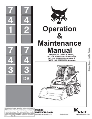
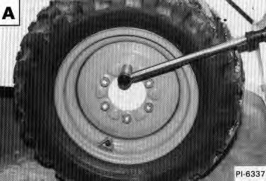
Place jackstands under the rear corners of the loader. One person must be in the operator’s seat, with the seat belt fastened and the seat bar lowered, until the lift arm support device is installed [A]
Start the engine and raise the lift arms all the way up. Have a second person install the lift arm support device over the rod of one of the lift cylinders.
The lift arm support device must be tight against the cylinder rod. Lower the lift arms slowly until the support device is held between the lift arm and the lift cylinder.
Operator Cab
The Bobcat loader has an operator cab (ROPS and FOPS) as standard equipment to protect the operator from rollover and falling objects.
Check with your dealer if the operator cab has been damaged.
Never modify operator cab by welding, grinding, drilling holes or adding attachments unless instructed to do so by Melroe Company. Changes to the cab can cause loss of operator protection from rollover and falling objects, and result in injury or death.
W–2069–1285
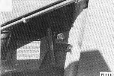
The operator cab fastening bolts and nuts must be tight [A]
Tighten to 40–50 ft.–lbs. (54–68 Nm) torque.
Both sets of fasteners at the front of the operator cab (ROPS) must be assembled as shown in this manual. Failure to secure ROPS correctly can cause injury or death.
W–2005–1189
Raising The Operator Cab
Before the cab or the lift arms are raised for service, jackstands must be put under the rear corners of the frame. Failure to use jackstands can allow the machine to tip backward causing injury or death.
W–2014–0895
Stop the loader on a level surface. Lower the lift arms fully. If the lift arms must be up while raising the operator cab, install a lift arm support device. (See Page 26.)
Remove the two fasteners (including the washers or plates) at the front corners of the operator cab [A]
OPERATOR CAB (Cont’d)
Raising
The Operator Cab (Cont’d)
If the lift arms are down, stand on the safety tread (lift arm crossmember) and lift on the top of the operator cab and the grab handle. Slowly lift until the operator cab is all the way up [A]
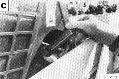
If the lift arms are up, install an approved lift arm support device. (See Page 26.) Stand in front of the loader. Lift on the grab handle and the bottom of the operator cab slowly until the operator cab is all the way up [B].
Lowering The Operator Cab
NOTE:Make sure the seat bar is fully raised or lowered when lowering the cab. Always use the grab handles to lower the cab.
If the lift arms are down, stand on the safety tread (lift arm crossmember). Pull down on the bottom of the operator cab and use the grab handles and the operator cab top until the operator cab is all the way down [A]
If the lift arms are held up by a lift arm support device, stand in front of the loader. Pull down on the bottom of the operator cab and use the grab handle until the cab is all the way down [B]
Install the two fasteners, (including the washers and plate). Tighten the nuts to 40–50 ft.–lbs. (54–69 Nm) torque [C]
Seat Bar Restraint System
The seat bar restraint system has a pivoting seat bar (Item 1) [A] with arm rests and has spring loaded interlocks for the lift and tilt control pedals. The operator controls the use of the seat bar. The seat bar in the down position helps to keep the operator in the seat. The interlocks require the operator to lower the seat bar in order to operate the foot pedal controls. When the seat bar is up, the lift and tilt control pedals are locked when returned to the neutral position .
Avoid Injury Or Death
The seat bar system must lock the lift and tilt control pedals in neutral when the seat bar is up. Service the system if pedals do not lock correctly.
Inspecting The Seat Bar
Sit in the seat and fasten the seat belt. Engage the parking brake. Pull the seat bar all the way down. Start the engine. Operate each foot pedal to check both the lift and tilt functions. Raise the lift arms until the bucket is about 2 feet (600 mm) off the ground.
Raise the seat bar. Try to move each foot pedal. Pedals must be firmly locked in neutral position. There must be no motion of the lift arms or tilt (bucket) when the pedals are pushed.
Pull the seat bar down, lower the lift arms. Operate the lift pedals. While the lift arms are going up, raise the seat bar and the lift arms should stop.
Maintaining The Seat Bar
See the SERVICE SCHEDULE Page 25 and on the loader for correct service interval.
Clean any debris or dirt from the moving parts [A] & [B]. Inspect the linkage bolts and nuts for tightness. The correct torque is 25–28 ft.–lbs. (34–38 Nm).
Use general purpose grease to lubricate the seat barpivot points at each side of the cab [A]
If the seat bar system does not function correctly, check for free movement of each linkage part. Check for excessive wear. Adjust pedal control linkages. Replace parts that are worn or damaged. Use only genuine Melroe replacement parts.
Opening The Rear Door
Avoid Injury
Never service or adjust the machine when the engine is running unless instructed to do so in the manual.
Open the rear door to service the engine. Pull the door latch up and to the left to release the door latch [A] The door can then be opened to get to the engine.
Keep the rear door closed when operating the machine. Failure to do so could seriously injure a bystander.
Adjusting The Rear Door
Loosen the set screw (Item 1) [B]
Loosen the nut (Item 2) [B]
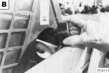
Turn the bolt (Item 3) [B] in or out, until the door contacts both the top and bottom of the loader frame (Item 1) [C] with the lever in the latched position.
NOTE:It takes approximately 50 lbs. (22 kg) of force to push the lever down when the latch is adjusted correctly.
With the set screw up, the flanges at the bolts (Item 2)[C] must be to the sides so that the set screw aligns with the flat surface of the end of the bolt.
Tighten the set screw (Item 1) [B].
Tighten the nut (Item 2) [B] to 65–70 ft.–lbs. (88–95 Nm) torque [B]
Air Cleaner Service
See the SERVICE SCHEDULE Page 25 for the interval to service the air cleaner system.
Check the air intake hoses for wear. Check if the air cleaner is damaged. Check all the connections.
741,743 & 743DS Only: Replace the large (outer) filter element only when the red ring shows in the window of the condition indicator [A] & [B]
741,743 & 743DS Only: Replace the inner filter every third time the outer filter is replaced or when the red ring still shows in the indicator window after the outer filter has been replaced.
742 Only: Replace the filter element only when the red ring shows in the window of the condition indicator [C]
NOTE:Before replacing the filter element, push the button on the condition indicator (Item 1) [A], [B] and [C], start the engine. If the red ring does not show, do not replace the filter element.
AIR CLEANER SERVICE (Cont’d)
Use the following procedure to replace the filter element(s):
Loosen the clamp (Item 1) [A] & [B] on the dust cup.
Remove the dust cup (Item 6) [A] & [B] and the outer element (Item 2) [A] & [B]
Remove the rubber boot (Item 3)[A] & [B] inside the dust cup and empty the dust cup.
Clean the inside of the air cleaner housing so the element has a smooth surface to contact at the seal (Item 4) [A] & [B]
Check the air cleaner housing for holes from corrosion. Install the new filter element(s).
NOTE:The washer (Item 5) [A] & [B] must be under the wing nut.
Install the dust cup so the arrow on the cup is up. Tighten the clamp.
Push the button on the indicator to remove the red ring.
Fuel System
Fuel Specifications
741,743, & 743DS Only: Use number 2 diesel fuel in the engine. During very cold temperatures, number 1 fuel can be used.
742 Only: Use regular gasoline in the engine.
Stop and cool the engine before adding fuel. NO SMOKING! Failure to obey warnings can cause an explosion or fire.
Remove the fuel fill cap (Item 1) [A] & [B].
Use a clean, approved safety container to add fuel of the correct specifications. Add fuel only in an area that has free movement of air and no open flames or sparks. NO SMOKING! [C]
After the fuel has been added install the fuel cap and tighten.
FUEL SYSTEM (Cont’d)
Fuel Filter (741,743 & 743DS Only)
The fuel filter is on the right upright in the engine compartment [A] & [B]
See the SERVICE SCHEDULE Page 25 for the interval to service the fuel filter.
If there is water in the water trap at the bottom of the filter, loosen the thumb screw (Item 1) [A] & [B].
Remove the water trap and clean the water from the trap.
Use the following procedure to replace the fuel filter element:
Clean the fuel filter area. Close the shut–off valve.
Use a wrench to loosen the fuel filter head bolts (Item 2) [A] & [B]. Remove the water trap and filter element (Item 3) [A] & [B]
Replace seals as needed.
Installation: Install the new filter element and water trap and hand tighten only.
Open the shut–off valve (Item 2) [C]
Fuel Filter (742)
The fuel filter (Item 1) [C] is in the fuel line by the shut–off valve (Item 2) [C]
See the SERVICE SCHEDULE Page 25 for the interval to service the fuel filter.
Clean the area around the fuel filter. Close the shut–off valve (Item 2) [C].
Loosen the nut and remove the tubeline (Item 3) [C].
Remove the element from the valve.
Install a new element with the arrow pointing in the direction of the carburetor.
Connect the tubeline and tighten the nut.Open the valve.
Start the engine and check for leaks.
Record the operating hours of the loader on the decal inside the rear door.
Always clean up spilled fuel or oil. Keep heat, flames, sparks or lighted tobacco away from fuel and oil. Failure to use care around combustibles can cause explosion or fire which can result in injury or death. W–2103–1285
FUEL SYSTEM (Cont’d)
Removing Air From The Fuel System (741)
After replacing the fuel filter element or when the fueltank has run out of fuel, the air must be removed from the fuel system before to starting the engine.
Diesel fuel or hydraulic fluid under pressure can penetrate skin or eyes, causing serious injury or death. Fluid leaks under pressure may not be visible. Use a piece of cardboard or wood to find leaks. Do not use your bare hand. Wear safety goggles. If fluid enters skin or eyes, get immediate medical attention from a physician familiar with this injury. W–2072–0496
Open the rear door. The engine must be cool.
Loosen the slotted plug (Item 1) [A]
Move the priming lever (Item 2) [A] until fuel flows from the plug (Item 1) [A] with no air bubbles showing.
Tighten the vent plug.
Loosen the pressure fitting at each injector (Item 1) [B].
Turn the engine until the fuel flows from the fittings with no air bubbles.
Tighten the fitting. Do not overtighten.
Removing Air From The Fuel System (743 & 743DS)
After replacing the fuel filter element or when the fueltank has run out of fuel, the air must be removed from the fuel system before starting the engine.
Open the rear door. The engine must be cool.
Open the vent plug (Item 1) [C].
Operate the hand pump (Item 2) [C] until fuel flows from the vent plug (Item 1) [C] with no air bubbles.
Tighten the vent plug.
Operate the hand pump until it feels solid.
Move the throttle control to minimum RPM. Loosen the valve (Item 1) [D] and squeeze the hand pump several times.
Start the engine. When the engine runs smoothly, close the valve (Item 1) [D].
Engine Lubrication System
Checking Engine Oil
Check the engine oil level every day.
Before starting the engine for the work shift,open the rear door. Remove the dipstick (Item 1) [A], [B] & [C]
Keep the oil level between the marks on the dipstick [D]. Use a good quality motor oil that meets API Service Classification of CD or better (See Oil Chart below).
RECOMMENDED SAE VISCOSITY NUMBER (LUBRICATION OILS FOR ENGINE CRANKCASE)
Keep Oil Level Between These Marks
TEMPERATURE RANGE ANTICIPATED BEFORE NEXT OIL CHANGE
741, 742, 743 & 743DS Bobcat Loader
ENGINE LUBRICATION SYSTEM (Cont’d) Replacement Of Oil And Filter
See the SERVICE SCHEDULE Page 25 for the service interval for replacing the engine oil and filter.
Operate the engine for about 15 minutes. Stop and engine. Lift the front of the loader about 6 inches and block it.
Open the drain (Item 1) [A], [B] & [C]
Remove the filter [(Item 2) [A] Page 36], (Item 2) [B] or (Item 1) [D]
Clean the filter housing surface. Put clean oil on the gasket of the new filter and install the filter and hand tighten only.
Close the drain. Remove the oil filler cap [(Item 3) [A] Page 36] or [(Item 2) [B] Page 36] or (Item 2) [D]. Fill to capacity. (See SPECIFICATIONS , Page 75.)
Always clean up spilled fuel or oil. Keep heat, flames, sparks or lighted tobacco away from fuel and oil. Failure to use care around combustibles can cause explosion or fire which can result in injury or death. W–2103–1285
Start the engine and let it run for about 5 minutes. Stop the engine. Check for leaks at the filter. Check the oil level. Add oil until the level is at the FULL mark on the dipstick. Install the oil filler cap.
NOTE:DO NOT overfill the crankcase.
Record the operating hours of the loader on the decal inside the rear door.
Cooling System
Checking The Coolant Level
741 Only
The engine is air–cooled and must have good air circulation to operate correctly.
Keep all shrouding in place and free of dents. Clean debris from the grill and the cooling fins, or overheating will result.
To clean the cooling fins, remove the blower housing cover (Item 1) [A]. Use an air hose to remove debris from the cylinder heads and the blower fan (Item 2) [A].
742 and 743 Only
Check the cooling system regularly to prevent over heating, loss of performance or engine damage.
Checking
The coolant recovery tank (Item 1) [B], or [C] must be at the FULL COLD mark when engine is cool.
Fill the radiator with pre–mixed coolant, 50% water and50 % anti–freeze.
Drain, flush and refill system with correct pre–mixed coolant whenever coolant becomes discolored.
Check the radiator cap (Item 1) [D] for correct pressure rating or overheating can result.
Check for leaks in the cooling system. Check for worn or damaged hoses, clamps or radiator. Check for loose or worn water pump belt.
Replace damaged parts immediately to prevent leaksand overheating.
Cleaning The Cooling system
Open the rear door.
Open the access panel at the top of the blower housing. Remove the grill.
• When fluids are under pressure.
• Flying debris or loose material is present.
• Engine is running.
• Tools are being used.
Wear safety glasses to prevent eye injury when any of the following conditions exist: W–2019–1285
Use air pressure or water pressure to remove the debris in the area of the radiator and oil cooler.
If debris is a problem, check with your dealer about the special debris screens.
COOLING SYSTEM (Cont’d)
Checking (743 DS)
Check the radiator regularly for correct operation and pressure.
Check the cooling system for leaks. See the SERVICE SCHEDULE Page 25 for the service interval. Replace parts as necessary to avoid overheating.
Use air pressure or water pressure to remove debris from the air duct screens (Item 1) [A]
Open the rear door.
Remove the panels (Item 1) [B].
Remove the grill (Item 2) [A]
Use air pressure or water pressure to remove debris from the radiator, the oil cooler and the surrounding area.
Replace the panels and the grill.
Close the rear door.
Coolant Replacement
Do not remove radiator cap when the engine is hot. You can be seriously burned.
W–2070–1285
742 Only: Remove the plug (Item 1) [C] and install a fitting in the hole. Connect a hose to the fitting. Drain the coolant into a container.
743 and 743 DS Only: Connect a hose to the valve or use a funnel to keep coolant from getting into the engine compartment. Open the valve (Item 1) [D] and drain coolant into a container.
Remove the grill. Remove the radiator cap. (Refer to Page 38 (Item 1) [D].)
742 Only: When all the coolant is removed, disconnect the fitting from the hole. Install and tighten the plug.
743 and 743 DS Only: Turn the lever (Item 1) [D] on the valve. When all the coolant is removed, close the valve.
Fill the radiator with premixed coolant and install the radiator cap.
Install the grill. Fill the coolant recovery tank 1/3 full with premixed coolant. (See Checking the Coolant Level, Page 38.)
Alternator Belt
Adjusting The Alternator Belt
Stop the engine.
741 Only: Remove the belt shield.
Loosen both the adjustment bolts (Item 1) [A] or [B] and move the alternator to set the belt tension at 5/16 inch (8 mm) movement between pulleys with 15 pounds of force. Tighten the adjustment bolt (Item 1) [A] or [B].
741 Only: Install the belt shield.
742 Only
Stop the engine.
Remove the belt shield [C]
Loosen the governor adjustment bolts (Item 1) [D]. Use a bar and adjust belt tension to 1/2 inch movement at the middle of the belt with 20 lbs. (89 N) pressure. Tighten the bolts.
Loosen the alternator adjustment bolts (Items 2 & 3) [D]. Move the alternator until there is 1/4 inch movement atthe middle of the belt with 20 lbs. (89 N) pressure. Tighten the bolts.
GOVERNOR (742)
Rod Adjustment
To adjust the governor linkage, use the following procedure:
1.Stop the engine.
2.Loosen the two screws (Item 1)[A] on the governor arm.
3.Hold the governor arm in the closed position (tothe left). Tighten the screws.
Install the belt shield before starting the engine.
Governor Oil Level
See the SERVICE SCHEDULE Page 25 for the service interval to check the oil level.
Remove the check plug (Item 1) [B] at the rear of governor.
If no oil flows, add SAE 10W–30 or 10W–40 until oilflows from the check plug
Install the plug and tighten.
ELECTRICAL SYSTEM Description
The loader has a 12 volt, negative ground alternator charging system.
Electrical System Service
If the two fuses become damaged, replace them with the same type and size fuses.
The battery cables must be clean and tight. Remove any acid or corrosion from the battery and cables with a sodium bicarbonate and water solution cover the battery terminals with Melroe Battery Saver (P/N 886398) to prevent corrosion [A].
Install the terminal covers.
Using An Extra Battery (Jump Starting)
Keep arcs, sparks, flames and lighted tobacco away from batteries. When jumping from booster battery make final connection (negative) at engine frame.
Do not jump start or charge a frozen or damaged battery. Warm battery to 60°F. (16°C.) before connecting to a charger. Unplug charger before connecting or disconnecting cables to battery. Never lean over battery while boosting, testing or charging.
Battery gas can explode and cause serious injury.
W–2066–1296
If it is necessary to use an extra battery to start theengine, BE CAREFUL! There must be one person in the operator’s seat and one person to connect and disconnect the battery cables.
The ignition must be in the OFF position.
The battery must be 12 volt.
Connect the end of the first cable to the positive terminal (+) of the booster battery. Connect the other end of the same cable to the starter [B].
Connect the end of the second cable to the negative terminal (–) of the booster battery. Connect the other end of the second cable to the engine [B]
Keep the cables away from moving parts.
Start the cables away from moving parts.
Start the engine.
After the engine has started, remove the ground cable connected to the engine first.
Remove the cable connected to the starter.
Batteries contain acid which burns eyes and skin on contact. Wear goggles, protective clothing and rubber gloves to keep acid off body.
In case of acid contact, wash immediately with water. In case of eye contact get prompt medical attention and wash eye with clean, cool water for at least 15 minutes.
If electrolyte is taken internally drink large quantities of water or milk! DO NOT induce vomiting. Get prompt medical attention.
Damage to the alternator can occur if:
• Engine is operated with battery cables disconnected.
• Battery cables are connected when using a fast charger or when welding on the loader (Remove both cables from the battery).
• Extra battery cables (booster cables) are connected wrong.
Batteries contain acid which burns eyes and skin on contact. Wear goggles, protective clothing and rubber gloves to keep acid off body.
In case of acid contact, wash immediately with water. In case of eye contact get prompt medical attention and wash eye with clean, cool water for at least 15 minutes.
If electrolyte is taken internally drink large quantities of water or milk! DO NOT induce vomiting. Get prompt medical attention.
Remove the battery cables, the negative cable first [A]
Remove the battery holddown clamp(Item 1) [B], [C] and [D].
Remove the battery from the loader.
ELECTRICAL SYSTEM (Cont’d)
Removing And Installing the Battery
Clean the terminals on the new battery [A] & [B].
Install the new battery, the holddown clamps and the terminal covers.
NOTE:DO NOT touch any metal with the battery terminals.
Install and tighten the battery cables. Connect the ground (negative) cable last to prevent sparks.
HYDRAULIC/HYDROSTATIC SYSTEM
The hydraulic and hydrostatic systems use the same hydraulic fluid reservoir.
The system has an engine driven implement pump that supplies fluid to the control valveand lift and tilt cylinders.
Fluid also goes from the control valve to the hydrostatic transmission pumps to provide charge pressure and cooling.
A #3 element filter and the hydrulic filter clean the fluidand protect the system from contamination.
The oil cooler is located above the radiator. The oil cooler is used for cooling the hydraulic fluid before it returns to the hydraulic pump.
Hydraulic/Hydrostatic Fluid Reservoir
Use only recommended fluid in the hydraulic system (See the SPECIFICATIONS section Page 75 for the correct fluid).
Checking And Adding Fluid
To check the fluid reservoir, use the following procedure:
Put the Bobcat loader on a level surface. Lower the lift arms and tilt the Bob–Tach fully backward. Stop the engine.
Check the fluid level shown in the sight gauge [A]
Remove the fill cap and add fluid as needed [B].
Hydraulic/Hydrostatic Fluid Replacement
See the SERVICE SCHEDULE Page 25 for the service interval. The fluid must be replaced if it becomes contaminated or after major repairs.
Remove the fill cap and lift the screen from the tank [C]
Check the screen for damage. Wash the screen in clean solvent.
Remove the hose from the filter housing. Let the fluid flow into a container [D]
HYDRAULIC/HYDROSTATIC SYSTEM (Cont’d)
Install the screen and cap.
Replace the #3 element filter and the hydraulic filter. Add fluid to the reservoir until the fluid shows in the sight gauge. DO NOT fill above the top mark of the sight gauge [A] (See Page 54).
Start the engine and operate the hydraulic controls. Check for leaks and add oil as necessary.
Hydraulic/Hydrostatic Filter Replacement
See the SERVICE SCHEDULE Page 25 for the service interval. The filter must be replaced when the hydrostatic warning light comes on during loader operation.
Remove the filter element (Item 1)[A], [B], and [C]. Drain fluid into the container.
Clean the surface of the filter head where the element contacts the head.
Put clean oil on the rubber gasket of the filter element. Install the filter element hand tight only.
Diesel fuel or hydraulic fluid under pressure can penetrate skin or eyes, causing serious injury or death. Fluid leaks under pressure may not be visible. Use a piece of cardboard or wood to find leaks. Do not use your bare hand. Wear safety goggles. If fluid enters skin or eyes, get immediate medical attention from a physician familiar with this injury.
W–2072–0496
Check for leaks after operating the loader.
Record the operating hours of the loader on the decal inside the rear door [D]
Always clean up spilled fuel or oil. Keep heat, flames, sparks or lighted tobacco away from fuel and oil. Failure to use care around combustibles can cause explosion or fire which can result in injury or death.
W–2103–1285
Spark Arrestor Muffler
See SERVICE SCHEDULE Page 25. Do not operatewith defect.
This loader is factory equipped with a U.S.D.A. Forestry Service approved spark arrestor muffler. It is necessary to do maintenance on this spark arrestor muffler to keep it in working condition. The spark arrestor muffler must be serviced by dumping the spark chamber every 100 hours of operation.
If this machine is operated on flammable forest, brush or grass covered land, it must be equipped with a spark arrestor attached to the exhaust system and maintained in working order. Failure to do so will be in violation of California State Law, Section 4442 PRC.
Make reference to local laws and regulations for spark arrestor requirements.
Stop the engine and open the rear door.
Stop engine and allow the muffler to cool before cleaning the spark chamber. Wear safety goggles. Failure to obey can cause serious injury.
W–2011–1285
Remove the plug at the bottom of the muffler (Item 1) [A] and [B].
Never use machine in atmosphere with explosive dust or gases or where exhaust can contact flammable material. Failure to obey warnings can cause injury or death.
W–2068–1285
Start the engine.
Wearing Safety goggles, have a second perosn hold a block of wood over the outlet of the muffler (with the engine running) for about 10 seconds.
Stop the engine and install the plug. Close the rear door.
FINAL DRIVE TRANSMISSION (Chaincase)
The chaincase contains the final drive sprockets and the chains and is filled with the same type of fluid as the hydraulic/hydrostatic system. See SPECIFICATIONS section Page 75.
To check the chaincase, use the following procedure: Put the Bobcat loader on a level surface. Remove the plug at the front of the transmission housing (Item 1) [A]. If oil can be reached withthe tip of your finger through the hole the oil level is correct.
If the level is low, add oil through the check plug hole until the oil flows from the hole. Install and tighten the plug.
Tire Maintenance
Tire Rotation
Check the tires regularly for wear, damage and pressure, See SPECIFICATIONS section for correct tire pressure, Page 75.
It is important to keep the same size tires on each side of the loader to avoid excessive wear. If different speed and cause excessive wear. When a tire wears, always install two new tires on the same side of the loader. The tread bars of all tires must move in the same direction.
Do not inflate tires above specified pressure. Failure to use correct tire mounting procedure can cause an explosion which can result in injury or death.
W–2078–1285
Recommended tire pressure must be maintained to avoid excessive tire wear and loss of stability and handling capability. Tires are sometimes inflated above or below operating pressure for shipping. Check for the correct pressure before operating the loader.
Tire Inflation
Tires are to be repaired only by an authorized person using the proper procedures and safety equipment. Tires and rims must always be checked for proper size before mounting. Check rim and tire bead for damage.
The rim flange must be cleaned and free of rust. The tire bead and rim flange must be lubricated with a rubber lubricant before mounting the tire to avoid damage tothe rim or tire. When inflating a tire, avoid excess pressure which can rupture the tire and cause serious injury. During inflating of the tire, check the tire pressure frequently to avoid over–inflation.
TIRE MAINTENANCE (Cont’d)
Tire Installation on Rim
If the tires are changed on the rims, avoid excess pressure which can rupture the tire and cause serious personal injury. During inflation of the tire, check the tire pressure frequently to avoid over inflation.
The rim must be cleaned and free of rust. Also the tire bead and rim flange must be lubricated with a rubber lubricant before mounting the tire on the rim to avoid damage to the tire and rim.
Tire Pressure
Recommended tire pressure must be maintained to avoid loss of stability and handling capability.
Check for correct pressure before operating the loader. The correct tire pressure is 45–55 PSI (310–379 kPa) for standard and 30–35 PSI (207–241 kPa) for floatation tires.
Wheel Nuts
See the SERVICE SCHEDULE Page 25 for the service interval to check wheel nuts.
The correct torque is 105–115 ft.–lbs. (142–156 Nm) [A]
Loader Lubrication
Lubricate the Bobcat loader as specified in theSERVICE SCHEDULE Page 25 for the best performance of the loader [B].
Always use good quality lithium based multi–purpose grease when you lubricate the Bobcat loader. Apply the lubricant until the extra grease shows.
LOADER LUBRICATION (Cont’d)
Lubricate the seat rails for easy movement.
See the SERVICE SCHEDULE Page 25 for service interval to grease the u–joints.
Grease the unimversal joints (Item 1) [A] and spline with special u–joint lubricant. See your dealer.
Lubricate the mounting (pivot assemblies) of the seat bar [B]
Raise the operator cab (Refer to Page 27 for the correct procedure). Grease the pivot bearings. See the SERVICE SCHEDULE Page 25 for the correct service interval).
Add oil or grease as needed to the steering control shaft [D]
BOB–TACH
Check for free movement of wedges and Bob–Tach levers.
The wedges must extend far enough to engage theholes in the attachment [A].
Avoid Injury Or Death
When operating the machine:
• Keep the seat belt fastened snugly.
• The seat bar must be lowered.
• Keep your feet on the pedal controls.
W–2046–0595
Replace wedges that are bent or broken.
Auxiliary Control Lockbolt
The quxiliary control has a lockbolt thatmust be removed to use the auxiliary hydraulics.
Raise the operator cab. (See Page 27 for the correct procedure.)
Remove the nut and bolt at the right hand steering lever [B].
Pivot Pins
All pivot pins, lift arms, Bob–Tach and cylinders have a large pin held in position with lockbolts (Item 1) [C]
Brake Pedal Adjustment
Loosen the lock nut (Item 1) [D] and turn the nut on the linkage rod (Item 2) [D] to adjust the brake pedal.
There must be 1/4 inch (6,35 mm) of movement under the bottom edge (heel) of the brake pedal.
Tighten the jam nut when the adjustment is correct.
Troubleshooting
The following information identifies loader problems which can occur most often. Service procedures for correcting loader problems can be found in this manual on the pages indicated. Some procedures are marked D/S (Dealer Service) and must be performed only by qualified Bobcat service personnel. Instructions are necessary before operating or servicing machine. Read Operation & Maintenance Manuals, Handbook and signs (decals) on machine. Follow warnings and instructions in the manuals when making repairs, adjustments or servicing. Check for correct function after adjustments, repairs or service. Failure to follow instructions can cause injury or death W–2003–1289
Engine won’t turn over with starter.
Battery has low charge.
Cables loose or dirty.
Damaged starter, solenoid or wiring.
Charge battery and find cause of discharge.
Clean and tighten the battery cables.
Check the starting circuit. Repair as needed.
Engine turns with starter, but is difficult to start.
Wrong starting procedure.
Air in the fuel.
Auxiliary control lever orlift pedal is in detent
No fuel in tank.
Vent in fuel filler cap is plugged.
Dirt or water in fuel system.
Fuel filter is dirty.
Hole in fuel line.
Weak battery.
Wrong oil in engine.
Cylinder compression is low.
Engine has overheated. Poor fuel quality.
Use correct starting procedure. Remove air from the fuel system. Take out of detent.
Add fuel.
Clean the vent.
Repair as needed. Install a new filter.
Repair as needed.
Charge or replace battery.
See Oil Specifications.
Recondition the engine.
Check cooling system.
Use fresh, good quality fuel.
Repair as needed.
Engine has little power or runs rough.
D/S = Dealer Service Only
Injectors are not working correctly. Dirt, water or air in fuel system.
Clean and repair as needed.
TROUBLESHOOTING THE ENGINE (Cont’d)
Problem Correction Cause
Engine has little power or runs rough (Cont’d).
Engine is hot.
Restricted exhaust.
Dirty air cleaner
Cylinder compression is low.
See Engine Overheats
Clean exhaust system
Install new element.
Recondition the engine.
Engine overheats.
Restriction in cooling air flow.
Blower shroud damaged or missing.
Engine is overheated.
Check for debris on radiator grill.
Check shroud and repair or replace as needed. Run
Troubleshooting The Drive System
Problem Correction Cause
No drive on both sides.
Hydraulic fluid is low.
Damaged hydraulic pump.
Hydrostatic system is damaged.
Check oil level. Add as needed.
Check condition of pump and replace as needed.
Check hydrostatic system.
No drive on one side.
Control linkage is disconnected.
Hydrostatic system is damaged.
Repair linkage.
Check hydrostatic system and make repair as needed.
Machine pulls to one side.
Wrong tire pressure.
Steering linkage interference.
Damaged hydrostatic system.
Check all tires for correctpressure.
Check steering linkage and adjust as needed.
Check system. Repair as needed.
Machine moves when levers are in neutral.
System is overheating.
Steering linkage out of adjustment.
Hydraulic oil level is low.
Cooling system is dirty. Air restricted.
Low charge pressure (transmission light on).
Auxiliary control in detent.
Loader is overloaded.
Adjust steering linkage.
Check oil level and add as needed.
Clean cooling system. Check for debris on radiator grill.
Check by–pass valve.
Take out of detent.
Use correct size attachment.
Parking brake will not hold.
D/S = Dealer Service Only
Hydrostatic transmission damage. Out of adjustment.
Check system and make repair.
Adjust parking brake.
Troubleshooting The Hydraulic System
No hydraulic action.
No hydraulic oil.
Pedals are disconnected.
Relief valve is damaged.
Hydraulic pump is damaged.
Hydraulic oil is too thick.
Check oil level and add as needed.
Check linkage. Repair as needed.
Replace the relief valve.
Check pump. Replace as needed.
Let machine warm up.
Hydraulic action is rough.
Hydraulic action is slow.
Hydraulic oil level is low.
Pedal is hitting floor or debris under pedal.
Cylinders leak internally.
Hydraulic pump is damaged.
Control valve is damaged.
Hydraulic oil is too thick.
Check oil level and add as needed.
Check adjustment. Remove debris.
Check condition of cylinders and repair as needed.
Check pump. Replace as needed.
Check valve and repair as needed.
Let machine warm up.
Hydraulic cylinders leak oil.
D/S = Dealer Service Only
Damage to cylinder rods or seals.
Repair cylinders.