14 minute read
MAINTENANCE SAFETY


Instructions are necessary before operating or servicing machine. Read Operation & Maintenance Manual, Handbook and signs (decals) on machine. Follow warnings and instructions in the manuals when making repairs, adjustments or servicing. Check for correct function after adjustments, repairs or service. Failure to follow instructions can cause injury or death.
Safety Alert Symbol:This symbol with a warning statement, means: “Warning, be alert! Your safety is involved!” Carefully read the message that follows.
Correct
Correct
Correct
Never service the Bobcat® Skid Steer Loader without instructions.
Wrong
Use the correct procedure to lift or lower operator cab with lift arms down.
Cleaning and maintenance are required daily.
Wrong Wrong
Have good ventilation when welding or grinding painted parts. Wear dust mask when grinding painted parts. Toxic dust and gas can be produced.
Wrong
Stop, cool and clean engine of flammable materials before checking fluids.
Never service or adjust loader with the engine running unless instructed to do so in the manual. Avoid contact with leaking hydraulic fluid or diesel fuel under pressure. It can penetrate the skin or eyes.
Never fill fuel tank with engine running, while smoking or when near open flame.
Vent exhaust to outside when engine must be run for service. Avoid exhaust fume leaks which can kill without warning. Exhaust system must be tightly sealed.
Never work on loader with lift arms up unless lift arms are held by an approved lift arm support device. Replace if damaged. Never modify equipment or add attachments not approved by Melroe Company.
Wrong Wrong
Keep body, jewelry and clothing away from moving parts, electrical contacts, hot parts and exhaust.
Wear eye protection to guard from battery acid, compressed springs, fluids under pressure and flying debris when engines are running or tools are used. Use eye protection approved for type of welding. Keep rear door closed except for service. Close and latch door before operating the loader.
Lead–acid batteries produce flammable and explosive gases. Keep arcs, sparks, flames and lighted tobacco away from batteries. Batteries contain acid which burns eyes or skin on contact. Wear protective clothing. If acid contacts body, flush well with water. For eye contact flush well and get immediate medical attention.
Maintenance procedures which are given in the Operation & Maintenance Manual can be performed by the owner/operator without any specific technical training. Maintenance procedures which arenot in the Operation & Maintenance Manual must be performed ONLY BY QUALIFIED BOBCAT SERVICE PERSONNEL. Always use genuine Bobcat replacement parts.
Service Schedule
Maintenance work must be done at regular intervals. Failure to do so will result in excessivewear and early failures. The service schedule is a guide for correct maintenance of the Bobcat loader.
Instructions are necessary before operating or servicing machine. Read Operation & Maintenance Manual, Handbook and signs (decals) on machine. Follow warnings and instructions in the manuals when making repairs, adjustments or servicing. Check for correct function after adjustments, repairs or service. Failure to follow instructions can cause injury or death.
Engine Air Cleaner Empty the dust cup & replace the filter element as needed.
Engine Oil Check the oil level & add oil as needed.
Engine Cooling SystemCheck coolant level in recovery tank. Clean debris from shrouds and grills.
Tires Check air pressure & for damage to the tires.
Operator Cab Check the fastening bolts, washers & nuts, Check the condition of the cab.
Seat Belt, Seat Bar & Check the condition of seat belt. Check the seat bar & Pedal Interlocks. pedal interlocks for correct operation..
Safety Signs & Check for damaged signs (decals) & safety treads.
Safety Treads. Replace any signs (decals) and safety treads that are damaged or worn.
All Loader Pivot PointsAdd grease to the fittings until the extra grease shows.
Hydraulic Fluid Check the fluid level in the reservoir & add fluid as needed.
Battery Check electrolyte level. Check battery cables for corrosion & tightness. Check covers.
Controls & Brake Check operation & adjust as needed
Bob–Tach Check locking levers & wedges for condition & operation.
Wheel Nuts Check for loose wheel nuts & tighten to 40–55 ft.–lbs (54–61 Nm) torque.
Alternator Drive Belt Check tension & make adjustment as needed.
Engine Fuel Filter Remove the water from the filter.
Engine Oil & Filter Replace oil & filter.
Hydraulic Filter ElementReplace filter element.
Spark Arrestor MufflerRemove the plug & clean the spark chamber.
Steering Levers Lubricate the grease fittings & the oil hole in the steering shaft.
Engine Fuel Filter Remove filter element.
Hydraulic Reservoir Fill Cap (Breather) Replace the breather cap.
Final Drive Transmission (Chaincase) Replace the fluid.
Hydraulic/Hydrostatic Reservoir Replace the fluid.
Check wheel nut torque every 8 hours for the first 24 hours. Also replace hydraulic/hydrostatic filter element when the transmission warning light stays on for five minutes after the fluid is at operating temperature. Or every 12 months.
Lift Arm Support Device
Two persons are needed to install the lift arm support device. One person must be in the operator’s seat with the seat belt fastened until the lift arm support device is installed.
Start the engine and raise the lift arms fully.
Have a second person install an approved lift arm support device (Item 1) [A] over the rod of one lift cylinders.
NOTE:Make sure the lift arm support device is tight against the cylinder rod.
Lower the lift arms slowly until the support device is held between the lift arms and the lift cylinder.
Never work on a machine with the lift arms up unless the lift arms are secured by a lift arm support device. Failure to use an approved lift arm support device can allow the lift arms or attachment to fall and cause injury or death.
Operator Cab
The Bobcat loader has an operator cab as standard equipment. The operator cab protects the operator as a roll–over protective structure (ROPS) and falling object protective structure (FOPS). The operator cab has the necessary warning signs.
Raising the Operator Cab
Stop the loader on a level surface.
Lower the lift arms fully.
Stop the engine and engage the parking brake.
Put jackstands under the rear of the loader.
Remove the two fasteners at the front corners of the operator cab [B] & [C]

NOTE:The wiring harness connector will disconnect when the operator cab is raised [D].
OPERATOR CAB (Cont’d)
Raising the Operator Cab (Cont’d)
EARLY MODELS; Two persons are needed to lift the operator cab. Avoid slippery surfaces when lifting the operator cab.
Stand on the ground (one person on each side) and lift the operator cab using the grab handles and the bottom of the cab [A]
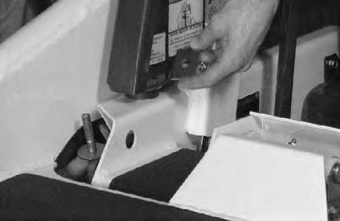
LATER MODELS; One person can lift the operator cab. Avoid slippery surfaces when lifting the cab. Stand on the ground and lift the operator cab using the grab handle and the bottom of the cab [B]
Lift slowly until the operator cab locks into the full raised position and the lock mechanism engages [C].
Lowering the Operator Cab
EARLY MODELS; Two persons are needed to lower the operator cab. Avoid slippery surfaces when lowering the operator cab. Stand on the ground (one person on each side) and lower the operator cab using the grab handles and the bottom of the cab [A].
LATER MODELS; One person can lower the operator cab. Avoid slippery surfaces when lowering the cab. Stand on the ground and lower the operator cab using the grab handle and the bottom of the cab [B]
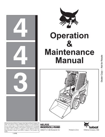
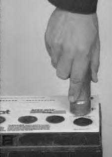
Pull down on the operator cab until it contacts the lock mechanism. Reach into the access opening of the cab and release the lock mechanism (Item 1) [D] by pushing and turning the locking lever until it stays engaged and the lock mechanism stays Un–locked [D]. REMOVE YOUR HAND BEFORE LOWERING THE OPERATOR CAB.
The cab must be held to prevent lowering while hand is in access hole.

OPERATOR CAB (Cont’d)
Lowering the Operator Cab (Cont’d)
Slowly lower the operator cab. Install the cab fasteners [A] & [B]
Connecting the wiring harness [C]
Emergency Exit
The front opening on the operator cab and rear window provides exits.
To exit through the rear window, use the following procedure:
1.Pull on the tag at the rear window to remove the rubber cord [D]
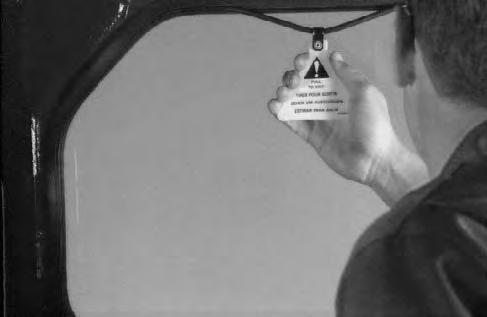
2.Push the rear window out of the rear of the operator cab.
3.Exit through the rear of the operator cab. ROPS/FOPS – Roll–Over Protective Structure per SAE J1040, and Falling Object Protective Structure per SAE J1043.
Seat Bar System
The seat bar system has a pivoting seat barwith arm rests and has spring loaded interlocks for the lift and tilt control pedals. The operator controls the use of the seat bar. The seat bar in the down position helps to keep the operator in the seat and unlocks the foot pedals. When the seat bar is up, the lift and tilt pedals are locked in neutral position.
Avoid Injury Or Death
The seat bar system must lock the lift and tilt control pedals in neutral when the seat bar is up. Service the system if pedals do not lock correctly. W–2105–1285
Seat Bar Inspection
Sit in the seat and fasten seat belt snugly. Engage the brake. Pull the seat bar all the way down. Start the engine. Operate each foot pedal to check both the lift arm and tilt functions. Raise the lift arms until the bucket is about two feet (600 mm) off the ground.
Raise the seat bar. Try to move each foot pedal. Pedals must be firmly locked in the neutral position. There must be no motion of the lift arms or tilt (bucket) when the pedals are pushed.
Pull the seat bar down, lower the lift arms fully and place the bucket flat on the ground. Stop the engine. Engage the brake. Raise the seat bar and operate the foot pedals to be sure that the pedals are firmly locked in the neutral position. Unfasten the seat belt.
Seat Bar Maintenance
Clean the debris or dirt from moving parts [A] & [B].
Inspect the linkage bolts and nuts for tightness 25–28 ft.–lbs. (34–38 Nm) torque.
Use general purpose grease to lubricate the seat barpivot points at each side of the cab[A]. If seat bar system does not function correctly, check for free movement of each linkage part. Check for excessive wear. Adjust pedal control linkages. Replace parts that are worn, or damaged. Use only genuine Melroe replacement parts.
Avoid Injury
Never service or adjust the machine when the engine is running unless instructed to do so in the manual.
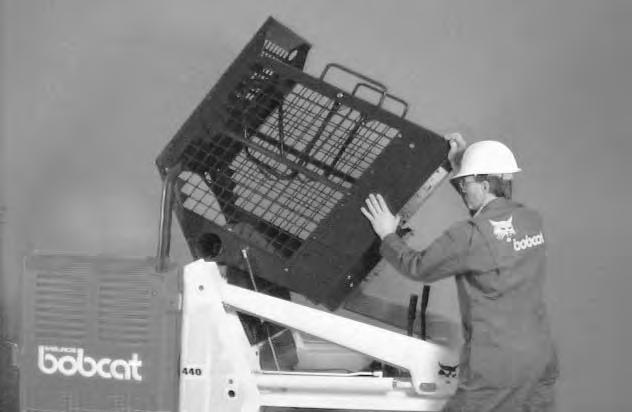
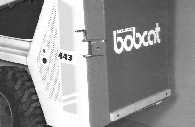
Open the rear door to service the engine. To release the door latch rotate the pin (Item 1)[A] clockwise and lift up. Open the rear door to the right.
Keep the rear door closed when operating the machine. Failure to do so could seriously injure a bystander.
Air Cleaner Service
See the Service Schedule Page 25 for the interval to service the air cleaner system.
NOTE: DO NOT use air pressure to clean the filter element.
Loosen the clamp (Item 1) [B] and remove the dust cup (Item 2) [B]
Remove the rubber cup (Item 3)[B] and remove dirt from the dust cup.
Remove the wing nut (Item 1) [C] to remove the filter element from the air cleaner housing.
Check the air intake hose for damage. Check the air cleaner housing for damage. Check to make sure all connections are tight.
Install a new filter element and tighten the wing nut. Be sure sealing washer (Item 1) [C] is in place.

Install the dust cup and tighten the clamp.

FUEL SYSTEM Specification
Use only specification high quality fuel. Use Grade No. 2 fuel above 40 °F. (4°C.). Use Grade No. 1 fuel at temperatures below 40°F. (4°C.).
W–2063–0887
Stop and cool the engine before adding fuel. NO SMOKING! Failure to obey warnings can cause an explosion or fire.
Always clean up spilled fuel or oil. Keep heat, flames, sparks or lighted tobacco away from fuel and oil. Failure to use care around combustibles can cause explosion or fire which can result in injury or death.
W–2103–1285
Filling the Fuel System
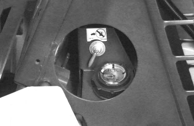
NOTE:The fuel gaug (Item 1) [A] and fuel shut–off valve (Item 2) [A] are located on the right side of the loader.
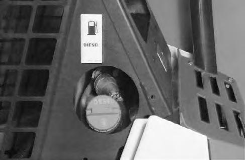
Remove the filler cap (Item 1) [B] located on the left side of the loader.
Use clean, approved safety container to add fuel of the correct specification.
The engine must be STOPPED and cool.
Add fuel only in an area that has a free movement of air and no open flames or sparks. NO SMOKING! [C].
Install and tighten the cap on the fuel tank.
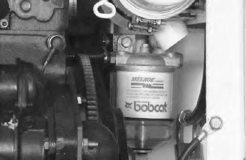
Fuel Filter
The fuel filter is located at the right hand side of the engine compartment below the air cleaner [D].
See the Service Schedule Page 25 for the service interval when to remove the water from the fuel filter.
Close the shut–off valve (Item 2) [A]
Loosen the drain (Item 1) [D] at the bottom of the filter element to drain the water from the filter. Tighten the drain plug.
Open the shut–off valve (Item 2) [A]
See the Service Schedule Page 25 for the service interval when to replace the fuel filter
Clean the area around the fuel filter. Close the shut–off valve (Item 2) [A]
Loosen the fuel filter bolt (Item 2) [D].
Remove the water trap and fuel filter [D]
Replace the seals as needed.
Install the new filter element and water trap.
Tighten the fuel filter bolt.
Open the shut–off valve (Item 2) [A]
FUEL SYSTEM (Cont’d)
Removing Air From the Fuel System
After replacing of the fuel filter element or when the fuel tank has run out of fuel, the airmust be removed from the fuel system before starting the engine.
Open the rear door.
Open the vent plug (Item 1)[A] on the top of the fuel filter.
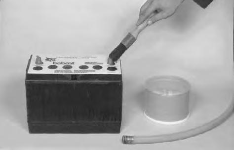
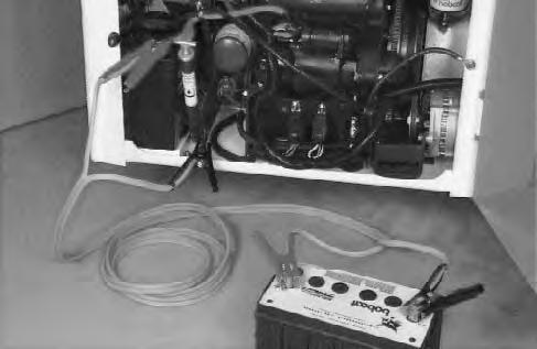
Operate the hand pump (Item 1) [B] through the hole in the left side of the operator’s cab until fuel flows from the vent plug with no air bubbles.

Close the vent plug on the top of the fuel filter.
Operate the hand pump (Item 1) [B] until it feels solid.
Put the engine stop control in the operating position.
Put the engine speed control at 1/2 position.
Start the engine. If the engine does not start after 30 seconds of cranking, repeat the procedure for removing air.
Put the engine speed control at 1/2 position.
Start the engine. If the engine does not start after 30 seconds of cranking, repeat the procedure for removing air.
After repeating the air removal procedure and the engine still does not start after 30 seconds of cranking, then do the following:
Raise the operator cab. (See Page 26.)
Open the valve (Item 1) [C] at the fuel injection pump.
Operate the hand pump (Item 1) [B] until the hand pump feels solid.
Close the valve (Item 1) [C]
Lower the operator cab. (See Page 27.)
W–2103–1285
Close the rear door.
Start the engine.
Engine Lubrication System
Check the oil level every day To check the oil level, stop the engine and open the rear door.
Remove the dipstick, wipe the dipstick, insert thedipstick again and recheck the oil level [A].
Keep the oil level between the marks on the dipstick.Use a good quality motor oil that has the correct API Service Classification of CC, CD or CE. (See the Oil Chart.)
Replacing Oil and Filter
See the Service Schedule Page 25 for the service interval for replacing the engine oil and filter.
Use the following procedure to replace the oil and filter:
1.Run the engine until it is at operating temperature. Stop the engine.
2.Open the rear door and removethe cap (Item 1) [B] from the end of the hose and drain the oil into a container.
3.Remove the filter (Item 2) [B].
4.Clean the filter housing surface. Put clean oil on the gasket of the new filter install the filter and tighten hand tight.
5.Remove the oil filler cap [C].
RECOMMENDED SAE VISCOSITY NUMBER (LUBRICATION OILS FOR ENGINE CRANKCASE)
TEMPERATURE RANGE ANTICIPATED BEFORE NEXT OIL CHANGE (DIESEL: USE API CLASSIFICATION CC, CD or CE)
Add the correct amount of oil (4 qts. (3,8 L) to the engine [C]. (See the Oil Chart for the correct oil.)
Install the oil fill cap and tighten.
Start the engine and let it run for several minutes. Stop the engine. Check for leaks at the filter. Check the oil level. Add oil as needed. DO NOT overfill the crankcase
COOLANT SYSTEM Checking the Coolant Level
The cooling system recovery tank (Item 1) [A] is located on the right upright in the engine compartment.
Check the cooling system every day to prevent over–heating, loss of performance or engine damage.
Check the coolant level, when the engine is cool. The recovery tank must be 1/3 full. Add coolantto the recovery tank when the coolant level is low [A]
Wear safety glasses to prevent eye injury when any of the following conditions exist:
• When fluids are under pressure.
• Flying debris or loose material is present.
• Engine is running.
• Tools are being used.
W–2019–1285
Check and clean the loader upright frame (both sides) as needed.
Removing The Coolant
Do not remove radiator cap when the engine is hot. You can be seriously burned.
W–2070–1285
The coolant drain valve (Item 1)[B] is on the front side of the engine block.
To remove the coolant from the cooling system, use the following procedure:
Raise the operator cab. (See Page 26.)
Connect a hose to the valve or use a funnel to keep the coolant from getting into the engine compartment.
Remove the radiator cap [C]
Turn the valve lever (Item 1)[D] so the lever is toward the outlet of the valve.
To fill the coolant system, use the following procedure:
Close the drain valve [B]
Fill the radiator with pre–mix 50% anti–freeze and 50% water.
Install the radiator cap.
Fill the coolant recovery tank to 1/3 mark.
ALTERNATOR DRIVE BELT Adjustment
Stop the engine and open the rear door. Loosen the three adjustment bolts (Item 1) [A].
Move the alternator bracket to the rear of the loader to set the belt tension at 1/4’’ (6,35 mm) movement [B].
Tighten the three adjustment bolts.
ELECTRICAL SYSTEM Description
The loader has a 12 volt, negative ground alternator charging system.
If the fuse in the instrument panel become damaged, replace it with the same type and size fuse.
Electrical System Service
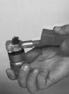
The battery cables must be clean and tight. Remove any acid or corrosion from the battery and cables with a baking soda and water solution. Cover the terminals of the battery with Melroe Battery Saver (P/N 886398) to prevent corrosion [A].
Install the terminal covers.
Using a Booster Battery (Jump Starting)
• Engine is operated with battery cables disconnected.
• Battery cables are connected when using a fast charger or when welding on the loader (Remove both cables from the battery).
• Extra battery cables (booster cables) are connected wrong.
I–2023–1285
If it is necessary to use an extra battery to start theengine, BE CAREFUL! There must be one person in the operator’s seat and one person to connect and disconnect the battery cables.
The key switch must be in the OFF position.
The battery must be 12 volt.
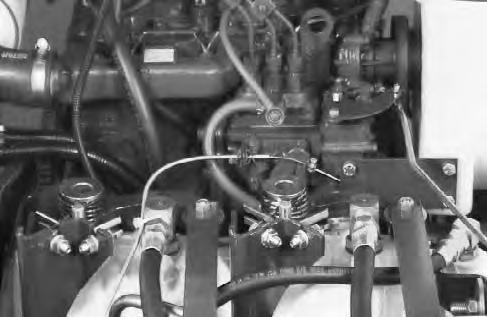
Connect the end of the first cable to the positive terminal (+) of the booster battery. Connect the other end of the same cable to the loader battery positive (+) terminal (Item 1) [B]
Connect the end of the second cable to the negative terminal (–) of the booster battery. Connect the other end (Item 2) [B] of second cable to the engine.
Keep the cables away from moving parts.
Start the engine.
After the engine has started, remove the ground cable connected to the engine first.
Remove the cable connected to the loader battery.
Batteries contain acid which burns eyes and skin on contact. Wear goggles, protective clothing and rubber gloves to keep acid off body.
In case of acid contact, wash immediately with water for several minutes and get medical attention in case of eye contact.
W–2065–1286
Keep arcs, sparks, flames and lighted tobacco away from batteries. When jumping from booster battery make final connection (negative) at engine frame.
Do not jump start or charge a frozen battery. Warm battery to 60°F. (16°C.) before connecting to a charger. Unplug charger before connecting or disconnecting cables to battery.
Battery gas can explode and cause serious injury.
W–2066–0490
ELECTRICAL SYSTEM (Cont’d) Battery Removal and Installation

Batteries contain acid which burns eyes and skin on contact. Wear goggles, protective clothing and rubber gloves to keep acid off body.
In case of acid contact, wash immediately with water for several minutes and get medical attention in case of eye contact.
Open the rear door. Disconnect the negative (–) battery cable first [A]
Disconnect the positive (+) battery cable [A]
Loosen the nut (Item 1) [A] below the hydraulic fill tube. Move the tube away from the battery.

Remove the battery holddown clamp (Item 2) [A].
Lift rear of the battery to remove the battery from the loader [B]
Always clean the terminals and cable ends when installing a new battery [C]
When installing the battery in the loader, do not touch any metal parts with the battery terminal posts.
Connect and tighten the battery cables. Connect the negative (–) cable last to prevent sparks.