22 minute read
Inspection And Maintenance


Warning
Failure to properly inspect and maintain the seat belt can cause lack of operator restraint resulting in serious injury or death.
W-2466-0703
Check the seat belt daily for correct function.
Inspect the seat belt system thoroughly yearly or more often if the machine is exposed to severe environmental conditions or applications.
The seat belt system should be repaired or replaced if it shows cuts, fraying, extreme or unusual wear, significant discolorations due to ultraviolet (UV) rays from the sun, dusty/dirty conditions, abrasion to the seat belt webbing, or damage to the buckle, latch plate, retractor (if equipped), or hardware.
B-22283
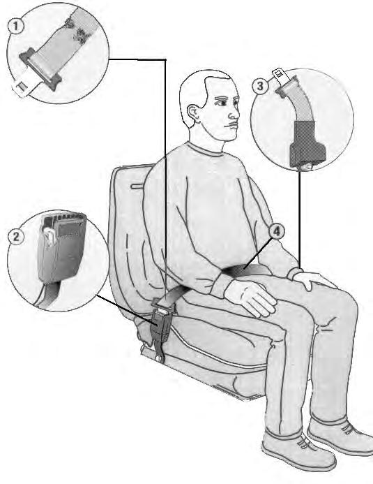
The items below are referenced in [Figure PM-2].
1.Check the seat belt webbing. If the system is equipped with a retractor, pull the webbing completely out and inspect the full length of the webbing. look for cuts, wear, fraying, dirt and stiffness.
2.Check the buckle and latch for proper function. Make sure latch plate is not excessively worn, deformed or buckle is not damaged.
3.Check the retractor web storage device (if equipped) by extending the seat belt webbing to determine if it extends and retracts the webbing correctly.
4.Check webbing in areas exposed to ultraviolet (UV) rays from the sun or extreme dust or dirt. If the original color of the webbing in these areas is extremely faded and / or the webbing is packed with dirt, the webbing strength may have weakened.
See your Bobcat dealer for approved seat belt system replacement parts for your machine.
Tailgate
Opening And Closing
Warning
Avoid Injury Or Death
Never service or adjust the machine when the engine is running unless instructed to do so in the manual.

Warning
Keep the rear door closed when operating the machine. Failure to do so could seriously injure a bystander.
Adjusting The Bumper
Figure PM-4
Release the latch (Item 1) [Figure PM-3] and pull the tailgate open.
Push firmly to close the tailgate.
Note: The tailgate can be locked using the start key.
The door bumper (Item 1) [Figure PM-4] can be adjusted for alignment with the tailgate.


Close the tailgate before operating the excavator.
Adjusting The Latch
Figure PM-5
The door latch (Item 1) [Figure PM-5] can be adjusted by loosening the two bolts, moving the latch, and tightening the two bolts.
Close the tailgate before operating the excavator.
Right Side Cover
Opening And Closing
Figure PM-6
Pull the latch (Item 1) [Figure PM-6] and raise the right side cover.
NOTE: The right side cover can be locked using the start key.
Adjusting The Latch


Figure PM-7
The right side cover latch (Item 1) [Figure PM-5] can be adjusted.
Loosen the nut (Item 2) for vertical adjustment and loosen the two bolts (Item 3) [Figure PM-5] for horizontal adjustment. Tighten the nut and bolts after the adjustment is made.
Close the right side cover before operating the excavator.
Cab Filters
Cleaning And Maintenance
Early Models
The recirculation filter must be cleaned regularly. The filter is located at the right of the operator seat.
The heater filter must be cleaned regularly. The filter is located at the left of the operator seat.


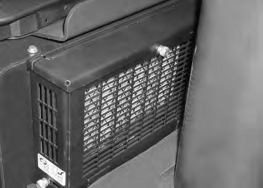
Remove the screw (Item 1) and cover (Item 2) [Figure PM-8]
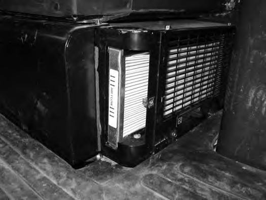
The filter must be cleaned regularly.
Pull the filter (Item 1) [Figure PM-9] away and out of the heater/AC housing.
Use low air pressure to clean the filter. Replace the filter when very dirty.
CAB FILTERS (CONT’D)
Cleaning And Maintenance (Cont’d)
Later Models
The recirculation filter must be cleaned regularly. The filter is located at the right of the operator seat.
The heater filter must be cleaned regularly. The filter is located at the left of the operator seat.


Turn the fastener (Item 1) 1/4 turn and remove the cover (Item 2) [Figure PM-11]
Installation:
The filter must be cleaned regularly.
Pull the filter (Item 1) [Figure PM-12] out of the heater housing.
Use low air pressure to clean the filter. Replace the filter when very dirty.
Air Cleaner Service
See the SERVICE SCHEDULE for the correct service interval. (See SERVICE SCHEDULE on Page PM-5.)
Daily Check
The air cleaner is located in the engine compartment. Open the tailgate to access the air cleaner for service. (See TAILGATE on Page PM-8.)
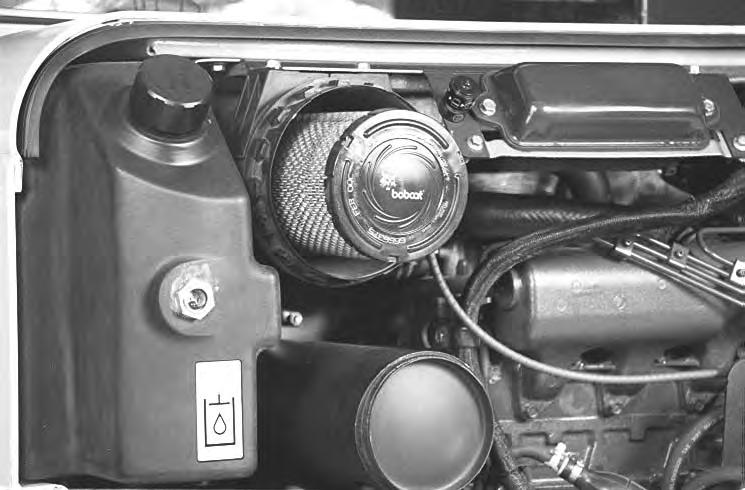

Check the condition indicator (Item 1) [Figure PM-14]. If the red ring shows in the condition indicator, the filter needs to be replaced.
Replace the inner filter every third time the outer filter is replaced or as indicated.
Replacing Filter Elements
Outer Filter
Release the two fasteners (Item 2) [Figure PM-14].
Remove and clean the dust cup (Item 3) [Figure PM-14].
Pull the outer filter (Item 1) [Figure PM-15] from the air cleaner housing.
Check the housing for damage. Clean the housing and the seal surface. DO NOT use compressed air.
Install a new filter.
Install the dust cup (Item 1) and engage the fasteners (Item 2) [Figure PM-16].
Check the air intake hose and the air cleaner housing for damage. Make sure all connections are tight.
After the outer filter has been replaced, press the button (Item 3) [Figure PM-16] on the end of the condition indicator and start the engine. Run at full RPM, then reduce engine speed and stop the engine. If the red ring shows in the condition indicator, replace the inner filter.

AIR CLEANER SERVICE (CONT’D)
Replacing Filter Elements (Cont’d)
Inner Filter
Only replace the inner filter under the following conditions:
•Replace the inner filter every third time the outer filter is replaced.
•After the outer filter has been replaced, press the button (Item 3) [Figure PM-16] on the end of the condition indicator and start the engine. Run at full RPM, then reduce engine speed and stop the engine. If the red ring shows in the condition indicator, replace the inner filter.

Remove the dust cup, outer filter and inner filter (Item 1) [Figure PM-17].
NOTE: Make sure all sealing surfaces are free of dirt and debris. DO NOT use compressed air.
Install the new inner filter (Item 1) [Figure PM-17]
Install the outer filter and the dust cup.
Press the button on the condition indicator to reset the condition indicator’s red ring.
Fuel System

Fuel Specifications
Use only clean, high quality diesel fuel, Grade No. 2 or Grade No. 1.
The following is a suggested blending guideline which should prevent fuel gelling problems during freezing temperature.
Filling The Fuel Tank
Figure PM-18
Contact your fuel supplier for local recommendations.
Warning
Stop and cool the engine before adding fuel. NO SMOKING! Failure to obey warnings can cause an explosion or fire.
W-2063-0887
Warning
Always clean up spilled fuel or oil. Keep heat, flames, sparks or lighted tobacco away from fuel and oil. Failure to use care around combustibles can cause explosion or fire which can result in injury or death.
W-2103-1285
Open the right side cover and remove the fuel fill cap (Item 1) [Figure PM-18]
Use a clean, approved safety container to add fuel. Add fuel only in an area that has a free movement of air and no flames or sparks. NO SMOKING!
Install and tighten the fuel fill cap.
Clean up any spilled fuel.
See the SERVICE SCHEDULE for the service interval when to remove water from or replace the fuel filter. (See SERVICE SCHEDULE on Page PM-5.)
FUEL SYSTEM (CONT’D)
Fuel Filters
Removing Water
Open the tailgate.
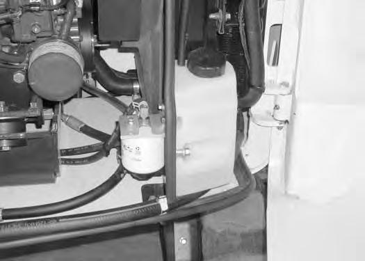
Figure PM-19
Loosen the drain (Item 1) [Figure PM-19] at the bottom of the filter to drain water from the filter into a container.
Clean up any spilled fuel.
Replacing Elements
Remove the filter (Item 2) [Figure PM-19].
Clean the area around the filter housing. Put clean oil on the seal of the new filter. Install the fuel filter and hand tighten.
Remove the air from the fuel system. (See Removing Air From The Fuel System on Page PM-16.)
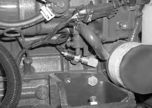
Draining The Fuel Tank
See the SERVICE SCHEDULE for the correct service interval. (See SERVICE SCHEDULE on Page PM-5.)
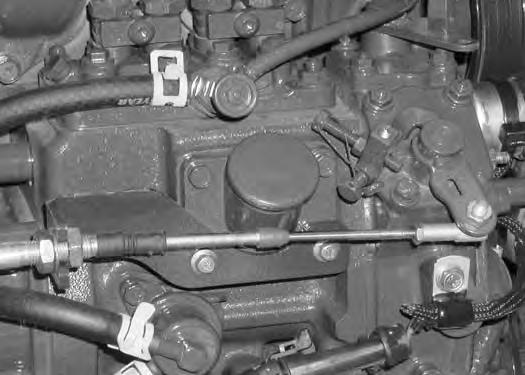
Figure PM-20
Remove the hose (Item 1) [Figure PM-20] from the fuel injection pump. Route the hose to the bottom of the engine compartment and out the tailgate.

Drain the fuel into a container.
Reuse, recycle or dispose of fuel in an environmentally safe manner.
Warning
Avoid Injury Or Death
Diesel fuel or hydraulic fluid under pressure can penetrate skin or eyes, causing serious injury or death. Fluid leaks under pressure may not be visible. Use a piece of cardboard or wood to find leaks. Do not use your bare hand. Wear safety goggles. If fluid enters skin or eyes, get immediate medical attention from a physician familiar with this injury.
W-2072-0807
FUEL SYSTEM (CONT’D)
Removing Air From The Fuel System
After replacing the fuel filter or when the fuel tank has run out of fuel, air must be removed from the fuel system before starting the engine.

Figure PM-21
Open the fuel filter vent (Item 1) and operate the hand pump (priming bulb) (Item 2) [Figure PM-21] until the fuel flows from the vent with no air bubbles.
Close the vent (Item 1) [Figure PM-21]
Start the engine. It may be necessary to open the vent (Item 1) [Figure PM-21] (at the fuel injection pump) briefly until the engine runs smoothly.
Warning
Diesel fuel or hydraulic fluid under pressure can penetrate skin or eyes, causing serious injury or death. Fluid leaks under pressure may not be visible. Use a piece of cardboard or wood to find leaks. Do not use your bare hand. Wear safety goggles. If fluid enters skin or eyes, get immediate medical attention from a physician familiar with this injury.
W-2072-0496
ENGINE LUBRICATION SYSTEM Checking And Adding Engine Oil

Check the engine oil every day before starting the engine for the work shift.
Engine Oil Chart
Open the tailgate and remove the dipstick (Item 1) [Figure PM-22]
Keep the oil level between the marks on the dipstick.
Use a good quality motor oil that meets the correct API Service Classification.
Use a good quality motor oil that meets the correct API Service Classification [Figure PM-23]
Install the dipstick and close the tailgate.
ENGINE LUBRICATION SYSTEM (CONT’D)
Removing And Replacing Oil And Filter
See the SERVICE SCHEDULE for the service interval for replacing the engine oil and filter. (See SERVICE SCHEDULE on Page PM-5.)
Run the engine until it is at operating temperature. Stop the engine.
Open the tailgate.
Remove the drain hose (Item 1) [Figure PM-24] from the storage position.
Figure PM-25
Remove the cap (Item 1) [Figure PM-25] from the drain hose. Drain the oil into a container.
Recycle or dispose of used oil in an environmentally safe manner.
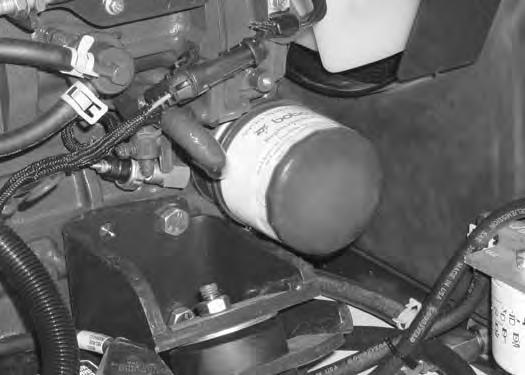
Remove the oil filter (Item 1) [Figure PM-26] and clean the filter housing surface.
Use a genuine Bobcat replacement filter. Put clean oil on the filter gasket. Install the filter and hand tighten.

Install and tighten the oil cap (Item 1) [Figure PM-25]
Remove the fill cap (Item 1) [Figure PM-27]
Put the correct amount of oil in the engine. (See Capacities on Page SPEC-9.)
Install the fill cap.
Start the engine and let it run for several minutes.
Stop the engine. Check for leaks at the oil filter. Check the oil level.
Add oil as needed if it is not at the top mark on the dipstick.
Engine Cooling System
Check the cooling system every day to prevent overheating, loss of performance or engine damage.
Cleaning
Open the tailgate.
Figure PM-28
Use air pressure or water pressure to clean the radiator and oil cooler (Item 1) [Figure PM-28]. Be careful not to damage fins when cleaning.

NOTE: Allow the cooling system and engine to cool before servicing or cleaning the cooling system.
Checking Level
Warning
AVOID BURNS
Do not remove radiator cap when the engine is hot. You can be seriously burned.
W-2070-1003
Warning
Wear safety glasses to prevent eye injury when any of the following conditions exist:
•When fluids are under pressure.
•Flying debris or loose material is present.
•Engine is running.
•Tools are being used.
W-2019-1285
Open the right side cover.
Figure PM-29
Check the coolant level in the coolant recovery tank (Item 1) [Figure PM-29]
The coolant level must be between the MIN and MAX marks on the coolant recovery tank (Item 1) [Figure PM29] when the engine is cold.
NOTE: The cooling system is factory filled with propylene glycol (purple color). DO NOT mix propylene glycol with ethylene glycol.
Important
AVOID ENGINE DAMAGE
Always use the correct ratio of water to antifreeze.
Too much antifreeze reduces cooling system efficiency and may cause serious premature engine damage.
Too little antifreeze reduces the additives which protect the internal engine components; reduces the boiling point and freeze protection of the system.
Always add a premixed solution. Adding full strength concentrated coolant can cause serious premature engine damage.
I-2124-0497
ENGINE COOLING SYSTEM (CONT’D)
Removing And Replacing Coolant
See the SERVICE SCHEDULE for correct service intervals. (See SERVICE SCHEDULE on Page PM-5.)
Stop the engine. Open the tailgate
Warning
AVOID BURNS
Do not remove radiator cap when the engine is hot. You can be seriously burned.
Put a hose on the drain valve at the bottom of the radiator. Open the drain valve (Item 1) [Figure PM-32] and drain the coolant into a container.
When the engine is cool, loosen and remove the radiator cap (Item 1) [Figure PM-31]
Put a hose on the drain valve on the engine block. Open the drain valve (Item 1) [Figure PM-32] and drain the coolant into a container.
After all the coolant is removed, close both drain valves. Recycle or dispose of the used coolant in an environmentally safe manner.
Mix the coolant in a separate container. (See Capacities on Page SPEC-9.)
NOTE: The cooling system is factory filled with propylene glycol (purple color). DO NOT mix propylene glycol with ethylene glycol.
Add premixed coolant; 47% water and 53% propylene glycol to the recovery tank if the coolant level is low.
One gallon and one pint of propylene glycol mixed with one gallon of water is the correct mixture of coolant to provide a -34°F (-37°C) freeze protection.

Use a refractometer to check the condition of propylene glycol in your cooling system.
Add premixed coolant until the level is correct.
Run the engine until it is at operating temperature. Stop the engine. Check the coolant level and add as needed. Be sure the radiator cap is tight.
Add coolant to the recovery tank as needed.
Close the tailgate.
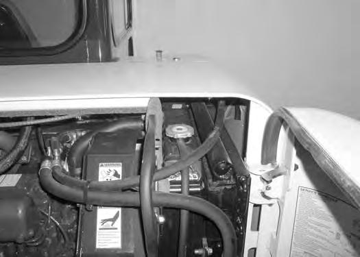
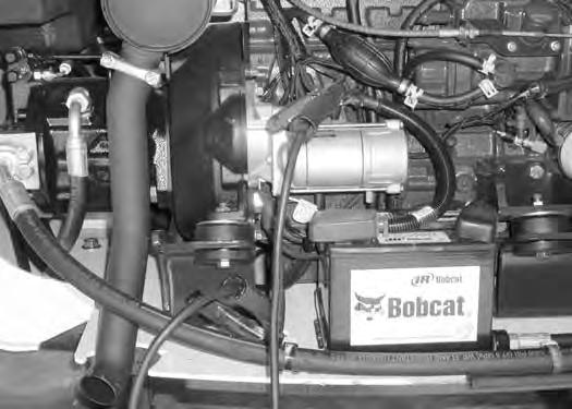
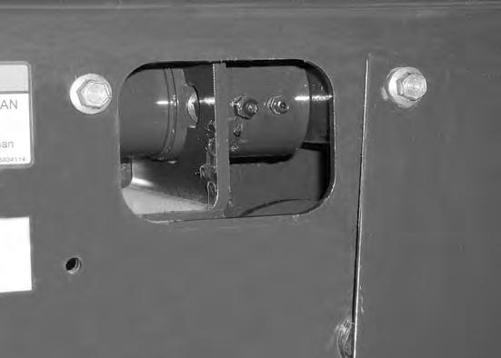
ELECTRICAL SYSTEM Description
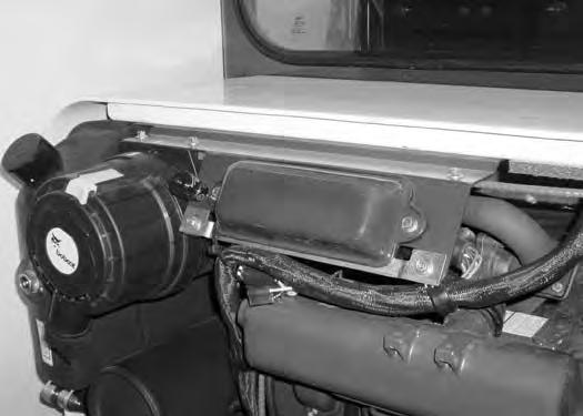
Figure PM-33
The excavator has a 12 volt, negative ground electrical system. The electrical system is protected by fuses located at the top of the engine compartment (Item 1) [Figure PM-33]. The fuses will protect the electrical system when there is an electrical overload. The reason for the overload must be found before starting the engine again.
The battery cables must be clean and tight. Check the electrolyte level in the battery. Add distilled water as needed. Remove acid or corrosion from the battery and cables with a sodium bicarbonate and water solution.
Put Battery Saver P/N 6664458 or grease on the battery terminals and cable ends to prevent corrosion.
Warning
AVOID INJURY OR DEATH
Batteries contain acid which burns eyes and skin on contact. Wear goggles, protective clothing and rubber gloves to keep acid off body.
In case of acid contact, wash immediately with water. In case of eye contact get prompt medical attention and wash eye with clean, cool water for at least 15 minutes.
If electrolyte is taken internally drink large quantities of water or milk! DO NOT induce vomiting. Get prompt medical attention.
W-2065-0807
Fuse And Relay Location / Identification

A decal is inside the cover to show location and amp ratings.
Remove the cover to check or replace the fuses and relays.
Figure PM-34
The location and sizes are shown below and [Figure PM34]
Always replace fuses using the same type and capacity.
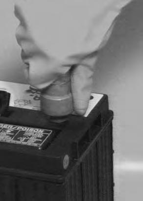
ELECTRICAL SYSTEM (CONT’D)
Battery Maintenance
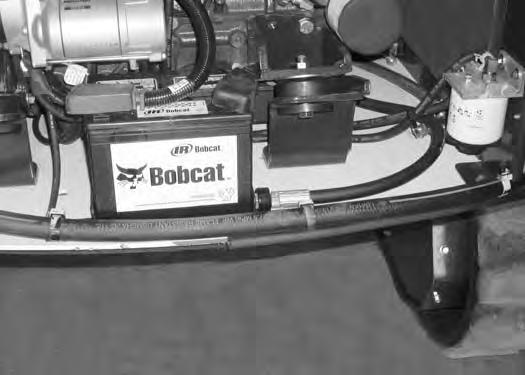
Open the tailgate.
The battery cables must be clean and tight [Figure PM36]. Remove acid or corrosion from the battery and cables using a sodium bicarbonate and water solution. Cover the battery terminals and cable ends with battery saver grease to prevent corrosion.


Check for broken or loose connections.
If the battery cables are removed for any reason, disconnect the negative (-) cable first. When installing the battery cables, make the last connection the negative (-) cable to the battery.
The original equipment battery is maintenance free. If a replacement battery is installed, check the electrolyte level in the battery.
If the electrolyte level is lower than 0.50 inch (13 mm) above the plates, add distilled water only.
Warning
Batteries contain acid which burns eyes and skin on contact. Wear goggles, protective clothing and rubber gloves to keep acid off body.
In case of acid contact, wash immediately with water. In case of eye contact get prompt medical attention and wash eye with clean, cool water for at least 15 minutes.
If electrolyte is taken internally drink large quantities of water or milk! DO NOT induce vomiting. Get prompt medical attention.
ELECTRICAL SYSTEM (CONT’D)
Using A Booster Battery (Jump Starting)
Important
If jump starting the excavator from a second machine:
When jump starting the excavator from a battery installed in a second machine. Make sure the second machine is NOT running while using the glow plugs. High voltage spikes from a running machine can burn out the glow plugs.
I-2060-0195
If it is necessary to use a booster battery to start the engine. BE CAREFUL! There must be one person in the operator's seat and one person to connect and disconnect the battery cables.
Engage the upperstructure slew lock. Be sure the key switch is OFF. The booster battery must be 12 volt.
Open the tailgate.
Figure PM-37
Connect one end of the first cable to the positive (+) terminal of the booster battery. Connect the other end of the same cable to the positive (+) terminal (Item 1) [Figure PM-37] of the excavator starter.
Connect one end of the second cable to the negative (-) terminal of the booster battery. Connect the other end of the same cable to the negative excavator cable (Item 2) [Figure PM-37] where it is fastened to the frame.
Start the engine. After the engine has started, remove the ground (-) cable first (Item 2) [Figure PM-37]
Disconnect the cable from the excavator starter (Item 1) [Figure PM-37].
NOTE: (See Cold Temperature Starting on Page OI28)
Important
Damage to the alternator can occur if:
•Engine is operated with battery cables disconnected.
•Battery cables are connected when using a fast charger or when welding on the excavator. (Remove both cables from the battery.)
•Extra battery cables (booster cables) are connected wrong.
I-2222-0903
Warning
Batteries contain acid which burns eyes and skin on contact. Wear goggles, protective clothing and rubber gloves to keep acid off body.
In case of acid contact, wash immediately with water. In case of eye contact get prompt medical attention and wash eye with clean, cool water for at least 15 minutes.
If electrolyte is taken internally drink large quantities of water or milk! DO NOT induce vomiting. Get prompt medical attention.
W-2065-1296
ELECTRICAL SYSTEM (CONT’D)
Removing And Installing Battery
Open the tailgate.
Figure PM-38
Disconnect the negative (-) cable (Item 1) [Figure PM35] first.
Disconnect the positive (+) cable (Item 2) [Figure PM35]
Remove the bolts (Item 3) [Figure PM-35] and remove the hold down clamp.
Remove the battery.
Always clean the terminals and the cable ends, even when installing a new battery.
Install the battery. Install the hold down clamp and tighten the bolts.
Connect the battery cables. Connect the negative (-) cable (Item 1) [Figure PM-35] last to prevent sparks.
Warning
Avoid Injury Or Death
Batteries contain acid which burns eyes and skin on contact. Wear goggles, protective clothing and rubber gloves to keep acid off body.
In case of acid contact, wash immediately with water. In case of eye contact get prompt medical attention and wash eye with clean, cool water for at least 15 minutes.
If electrolyte is taken internally drink large quantities of water or milk! DO NOT induce vomiting. Get prompt medical attention.
W-2065-0807
HYDRAULIC SYSTEM Checking And Adding Fluid
Put the machine on a level surface.
Retract the arm and bucket cylinders, put the bucket on the ground and lower the blade. Stop the engine.

Open the tailgate.
Check the hydraulic fluid level, it must be visible in the sight gauge (Item 1) [Figure PM-39].
Clean the surface around the reservoir (breather) cap and remove the cap from the reservoir (Item 2) [Figure PM-39]
Warning
Always clean up spilled fuel or oil. Keep heat, flames, sparks or lighted tobacco away from fuel and oil. Failure to use care around combustibles can cause explosion or fire which can result in injury or death.
W-2103-1285
Check the condition of the fill strainer screen (Item 1) [Figure PM-40]. Clean or replace as necessary.
Be sure the screen is installed before adding fluid.
Add the correct fluid to the reservoir until it is visible in the sight gauge. (See REGULAR MAINTENANCE ITEMS on Page V.)

Check the cap and clean as necessary. Replace the cap if damaged.
Install the cap.
Close the tailgate.
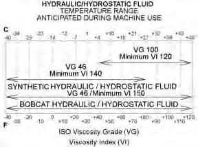
Hydraulic Fluid Chart
Figure PM-41
Use the correct hydraulic fluid shown in chart [Figure PM-41]
Add hydraulic fluid as needed to bring the level to the center of sight gauge (Item 1) [Figure PM-39]
Install the oil fill cap.
HYDRAULIC SYSTEM (CONT’D)
Removing And Replacing Hydraulic Filters

Warning
Avoid Injury Or Death
Always clean up spilled fuel or oil. Keep heat, flames, sparks or lighted tobacco away from fuel and oil. Failure to use care around combustibles can cause explosion or fire which can result in injury or death.
W-2103-0807
See the SERVICE SCHEDULE for the correct service interval. (See SERVICE SCHEDULEon PagePM-5.)
Open the right side cover.
Figure PM-42
Remove the primary hydraulic filter (Item 1) [Figure PM42].
Clean the housing where the filter gasket makes contact.
Put clean hydraulic fluid on the gasket. Install the new filter and hand tighten only. Use a genuine Bobcat replacement filter.
Remove the case drain filter (Item 2) [Figure PM-42].
Clean the housing where the filter gasket makes contact.
Put clean hydraulic fluid on the gasket. Install the new filter and hand tighten only.
HYDRAULIC SYSTEM (CONT’D)
Removing And Replacing Hydraulic Fluid
See the SERVICE SCHEDULE for the correct service interval. (See SERVICE SCHEDULEon PagePM-5.)
Warning
AVOID INJURY OR DEATH
Diesel fuel or hydraulic fluid under pressure can penetrate skin or eyes, causing serious injury or death. Fluid leaks under pressure may not be visible. Use a piece of cardboard or wood to find leaks. Do not use your bare hand. Wear safety goggles. If fluid enters skin or eyes, get immediate medical attention from a physician familiar with this injury.
W-2072-0807
Retract the arm and bucket cylinders, lower the bucket to the ground. Lower the blade to the ground. Stop the engine.
Open the tailgate.
Pull the hydraulic reservoir drain hose (Item 1) [Figure PM-43] out of the excavator upperstructure.

Remove the drain hose cap (Item 2) [Figure PM-43]
Drain the fluid into a container.
Recycle or dispose of the fluid in an environmentally safe manner.
Reinstall the drain hose cap (Item 2) [Figure PM-43]
Always replace the filters when changing the hydraulic oil.
After the hydraulic fluid has been drained from the excavator or after the hydraulic pump has been serviced, the hydraulic pump must be flooded with hydraulic oil. Allow sufficient time for the hydraulic fluid to gravity feed into the hydraulic pump before starting the machine.
Recycle or dispose of the fluid in an environmentally safe manner.
Start the engine and operate the machine through the hydraulic functions. Stop the engine. Check the fluid level and add as needed.
Install new Bobcat hydraulic fluid. (See Capacities on Page SPEC-9.) (See Hydraulic Fluid Charton PagePM25.) (See REGULAR MAINTENANCE ITEMS on Page V.)
Spark Arrestor Muffler
Cleaning Procedure
See the SERVICE SCHEDULE for the correct service interval. (See SERVICE SCHEDULE on Page PM-5.)
Warning
Avoid Injury Or Death
When an engine is running in an enclosed area, fresh air must be added to avoid concentration of exhaust fumes. If the engine is stationary, vent the exhaust outside. Exhaust fumes contain odorless, invisible gases which can kill without warning.
W-2050-0807
Warning
Stop engine and allow the muffler to cool before cleaning the spark chamber. Wear safety goggles. Failure to obey can cause serious injury.
W-2011-1285
Warning
Never use machine in atmosphere with explosive dust or gases or where exhaust can contact flammable material. Failure to obey warnings can cause injury or death.
W-2068-1285
Warning
When the engine is running during service, the steering levers must be in neutral.
Failure to do so can cause injury or death.
W-2203-0595
Do not operate the excavator with a defective exhaust system.
Stop the engine. Open the tailgate.
Remove the plug (Item 1) [Figure PM-44] from the bottom of the muffler.
Start the engine and run for about 10 seconds while a second person, wearing safety glasses, holds a piece of wood over the outlet of the muffler. The carbon deposits will be forced out of the muffler plug hole (Item 1) [Figure PM-44]
Stop the engine. Install and tighten the plug.
Close the tailgate.
Track Tension
NOTE: The wear of undercarriage parts vary with working conditions and types of soil conditions. Maintain the correct track tension by inspecting regularly. For the correct service interval (See SERVICE SCHEDULE on Page PM-5.)
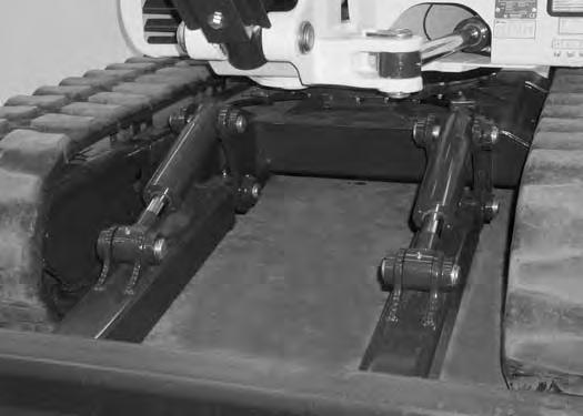
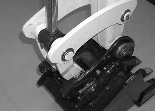
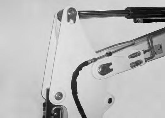
Adjusting
Raise one side of the machine (Approximately four inches) using the boom and arm [Figure PM-45]
Raise the blade fully and install jackstands under the blade and track frame (Item 1) [Figure PM-45]. Lower the boom until all machine weight is on the jackstands.

Stop the engine.
Warning
AVOID INJURY
Keep fingers and hands out of pinch points when checking the track tension.
W-2142-0903
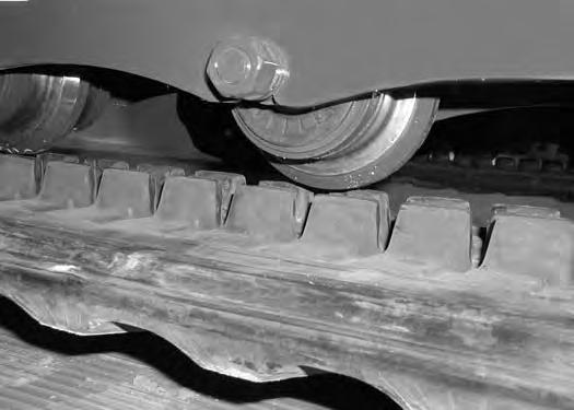
Rubber Track Clearance
Measure the clearance at the middle track roller. Do not get fingers into pinch points between the track and the track roller. Use a bolt or a dowel of the appropriate size to check the gap between the contact edge of the roller and the top edge of the track guide [Figure PM-46] & [Figure PM-47].
Rubber Track Clearance - 0.984-1.181 in. (25-30 mm).
TRACK TENSION (CONT’D)
Adjusting (Cont’d)
Steel Track Clearance
Figure PM-48
Measure the track clearance at the middle track roller. Do not get fingers into pinch points between the track and the track roller. Us a bolt or dowel of the appropriate size to check the gap between the contact edge of the roller and the top edge of the track guide [Figure PM-48]


Steel Track Clearance - 2.560-2.760 in. (65-70 mm).
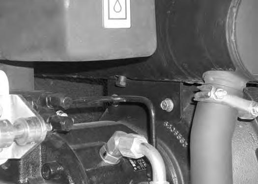
Add grease to the fitting (Item 1) [Figure PM-50] until the track tension is correct.
Loosen the two bolts from the cover (Item 1) [Figure PM49]. Pivot the cover downward.

Use tool MEL1560 (Item 1) [Figure PM-51] to loosen the bleed fitting (Item 2) [Figure PM-50] to release tension from the track.
NOTE: Do not loosen the grease fitting (Item 1) [Figure PM-50].
Repeat the procedure for the other side.
Travel Motor
Checking And Adding Oil
Figure PM-52
Park the excavator on a level surface with the plugs (Item 1 & 2) [Figure PM-52] in the position as shown.
Remove the plug (Item 1) [Figure PM-52]. The lube level must be at the bottom edge of the hole.
Add lubricant through the hole if the lube level is low. (See REGULAR MAINTENANCE ITEMS on Page V.)

Removing And Replacing Oil
For the correct service interval (See SERVICE SCHEDULE on Page PM-5.)
Park the excavator on a level surface with plugs (Item 1 & 2) [Figure PM-52] in the position shown. Remove both plugs and drain the lubricant into a container.
Warning
Avoid Injury Or Death
Always clean up spilled fuel or oil. Keep heat, flames, sparks or lighted tobacco away from fuel and oil. Failure to use care around combustibles can cause explosion or fire which can result in injury or death.
W-2103-0807
Install the bottom plug (Item 2 [Figure PM-52]). Add lubricant through the top plug hole until the lube level is at the bottom edge of the hole. (See REGULAR MAINTENANCE ITEMS on Page V.)
Install the plug (Item 1) [Figure PM-52]
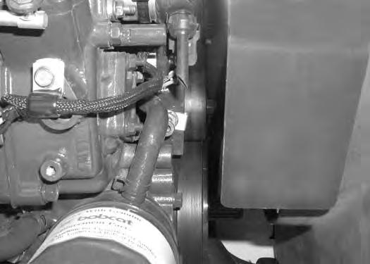
Alternator Belt
Belt Adjustment
Open the tailgate.
Figure PM-53
Loosen the nut (Item 1) on the belt idler pulley. Loosen the nut (Item 2) and tighten the bolt (Item 3) until the belt tension is correct. Tighten the two nuts (Item 1) & (Item 2) [Figure PM-53].
Figure PM-54
Using a belt tension gauge, measure the belt tension midway between the crankshaft pulley and alternator pulley [Figure PM-54]
Belt tension is as follows:
New belt 107-114 ft.-lb. (145-155 N•m)
Used belt 92-99 ft.-lb. (125-134 N•m)
Belt Replacement
Figure PM-55
Loosen the nut (Item 1) on the belt idler pulley. Loosen the nut (Item 2) and the bolt (Item 3) until the belt is loose [Figure PM-55]. Remove the old belt and install a new belt.
Tighten the bolt (Item 3) until the belt tension is correct. Tighten the two nuts (Item 1) & (Item 2) [Figure PM-55]
Warning
AVOID INJURY OR DEATH
•Do Not Operate with damaged or missing screens, shields or rubber deflectors.
•Stop engine before cleaning or servicing.
•Contact with moving parts or flying objects can cause injury or death.

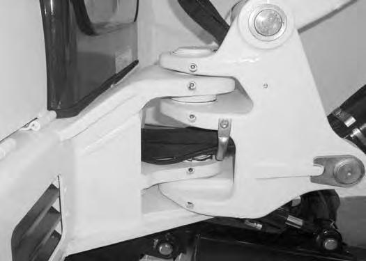
X-CHANGE Inspection And Maintenance
Inspect the X-Change for wear or damage. Inspect the XChange pins (Item 1) and hooks (Item 2) [Figure PM-56] (on the attachment) for wear or damage.
Repair or replace damaged parts.
Track Roller And Idler Lubrication
Procedure
The track rollers and idlers require no maintenance. The bearings are a sealed design.

Hydraulic X-Change (if equipped)
Inspect the X-Change for wear or damage. Inspect the XChange pins (Item 1) and hooks (Item 2) [Figure PM-57] (on the attachment) for wear or damage.
Inspect the hydraulic pins (Item 3) [Figure PM-57] (both sides) for wear or damage.
Inspect the retainer pin and clips (Item 4) [Figure PM-57] (both sides) for wear or damage. ONLY USE APPROVED RETAINER PINS AND CLIPS. Repair or replace damaged or missing parts.
Warning
Wear safety glasses to prevent eye injury when any of the following conditions exist:
•Pressurized fluids and springs or other stored energy components.
•Flying debris or loose material is present.
•Engine is running.
•Tools are being used.
W-2505-0604
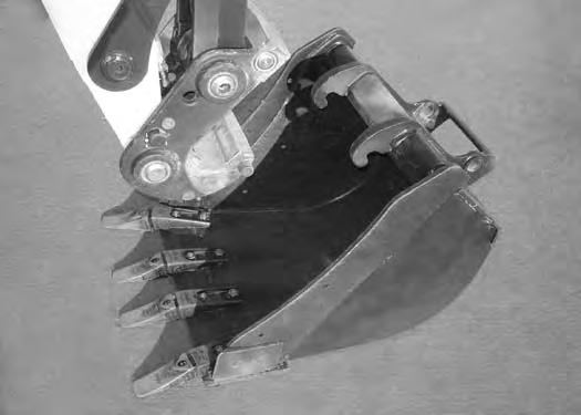
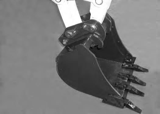
Position the bucket so the bucket teeth are at a 30° angle up from the ground for accessibility to the teeth.
Lower the boom until the bucket is fully on the ground. Stop the engine and exit the excavator.
NOTE: The later style tooth points and retaining pins can be used on the early style shanks.

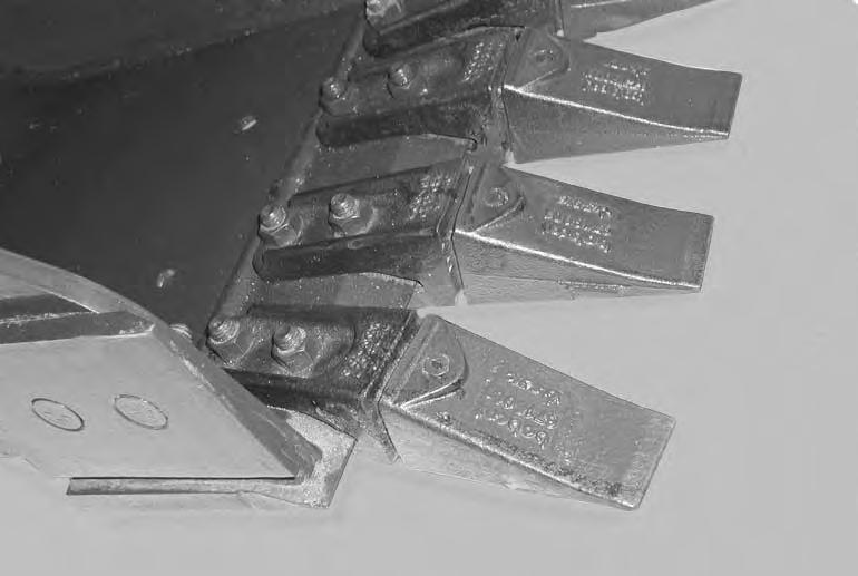
Early Style Bucket Teeth
Figure PM-58
Remove the retaining pin (Item 1) from the tooth point (Item 2) [Figure PM-58].
Remove the tooth point (Item 2) from the shank (Item 3) [Figure PM-58]
Installation: Position the new tooth point on the shank and install a new retaining pin. Install the retaining pin until it is flush with the top of the point.
Remove the two nuts (Item 1) and bolts from the tooth shank (Item 2) [Figure PM-59]. Remove the tooth shank.
Installation: Tighten the nuts to 90 - 100 ft.-lb. (125-135 N•m) torque.
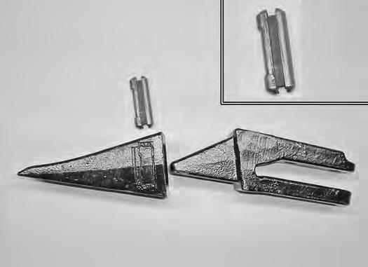
Later Style Bucket Teeth
Figure PM-60
The removal and installation procedure for the later style tooth point and tooth shank is the same as the early style.
The later style tooth has a unique retaining pin (Item 1). The retaining pin must be installed as shown [notch (Item 2) to the front] for proper fit and tooth retention. The side of the tooth point (Item 3) [Figure PM-60] also shows the correct orientation of the retaining pin.
Installation: Position the new tooth point on the shank and install a new retaining pin. Install the retaining pin until it is flush with the top of the point.
Lubricating The Excavator
Lubrication Locations
Lubricate the excavator as specified in the SERVICE SCHEDULE for the best performance of the machine.
(See SERVICE SCHEDULE on Page PM-5.)
Record the operating hours each time you lubricate the excavator.
Lubricate the excavator as specified in the SERVICE SCHEDULE for the best performance of the machine.
(See SERVICE SCHEDULEon PagePM-5.)
Always use a good quality lithium based multipurpose grease when lubricating the machine. Apply the lubricant until extra grease shows.
Lubricate the following locations on the excavator EVERY 8-10 HOURS:

LUBRICATING THE EXCAVATOR (CONT’D)
Lubrication Locations (Cont’d)

LUBRICATING THE EXCAVATOR (CONT’D)
Lubrication Locations (Cont’d)
Figure PM-68

18.Boom Swing Cylinder Base End (1) [Figure PM-68]
Lubricate the following locations on the hydraulic Excavator EVERY 50 HOURS :
19.Slew Circle (1) [Figure PM-68]
20.Slew Pinion (1) [Figure PM-68]. (Install 3 to 4 pumps of grease then rotate the upperstructure 90°. Install 3 to 4 pumps of grease and again rotate the upperstructure 90°. Repeat this until the slew pinion has been greased at four positions.)


