13 minute read
STARTING THE ENGINE (CONT’D)


Keyless WARNING
Avoid Injury Or Death
Advertisement
•Fasten seat belt, start and operate only from the operator seat.
•Never wear loose clothing when working near machine.
W-2135-1188
Perform the PRE-STARTING PROCEDURE. (See PRESTARTING PROCEDURE on Page OI-23.)
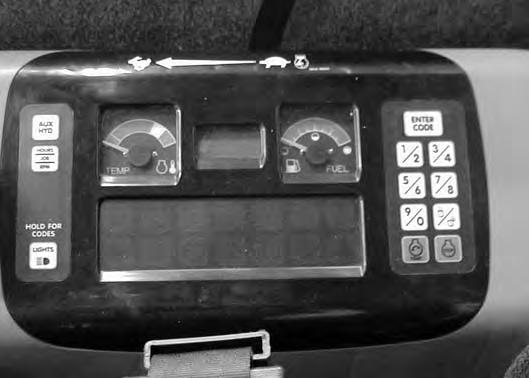
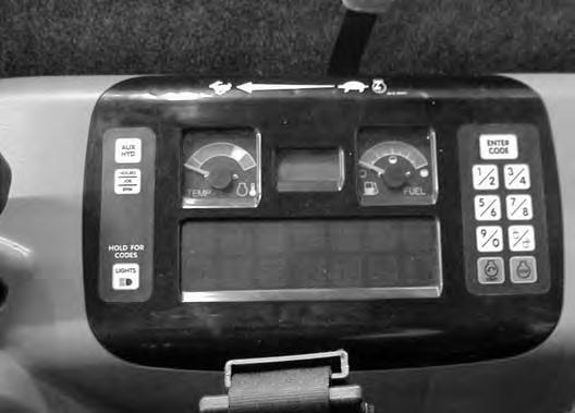
Press ENTER CODE Button (Item 1) [Figure OI-57]. The display will become lighted and there will be two short beeps, CodE will appear on the LCD.
Use the keypad (Item 2) [Figure OI-57] to enter the password. For each digit that you enter, a dash will appear on the LCD. (You have 40 seconds to enter the password or the process will abort and you will need to start over.) If the password was entered correctly, there will be one long beep.
NOTE: If the password was incorrect there will be three short beeps and “Error” will appear on the LCD. Press the ENTER CODE Button again and start over. After three failed attempts, you must wait three minutes to try again.
Press the START Button (Item 3) [Figure OI-57] and hold it until the engine starts.
Important
Do not engage the starter for longer than 15 seconds at a time. Longer use can damage the starter by overheating. Allow starter to cool for one minute before using starter again.
I-2034-0700
Press the STOP button (Item 4) [Figure OI-57] to stop the engine.
Stop the engine if the warning lights and alarm do not go OFF.
Check for the cause before starting the engine again.
Password Lockout Feature
See Password Lockout Feature. (See Passwords on Page SA-4.)
STARTING THE ENGINE (CONT’D)
Cold Temperature Starting
Warning
Do not use ether with glow plug (preheat) systems. Explosion can result which can cause injury, death, or severe engine damage.
W-2071-0903
If the temperature is below freezing, perform the following to make starting the engine easier:
•Replace the engine oil with the correct type and viscosity for the anticipated starting temperature. (See ENGINE LUBRICATION SYSTEM on Page PM17)
•Make sure the battery is fully charged:
•Install an engine heater, available from your Bobcat dealer.
NOTE: If the battery is discharged (but not frozen) a booster battery can be used to jump start the excavator. (See Using A Booster Battery (Jump Starting) on Page PM-23)
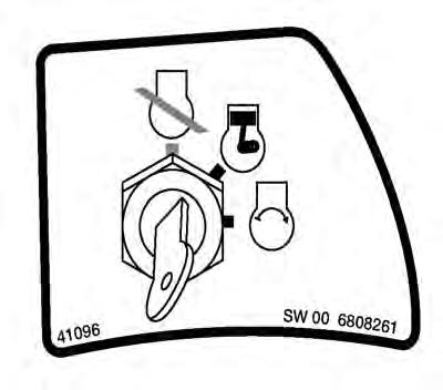
Key Switch
Figure OI-59
Push the speed control lever (Item 1) [Figure OI-58] fully forward.
Important
Do not engage the starter for longer than 15 seconds at a time. Longer use can damage the starter by overheating. Allow starter to cool for one minute before using starter again.
I-2034-0700
Turn the key to the ON position [Figure OI-59]
The preheat icon (Item 1) [Figure OI-60] will come ON. The glow plugs will automatically cycle. When the icon goes off, turn the key to start.
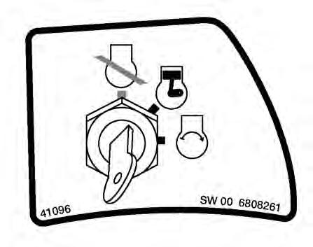
Release the key when the engine starts, it will return to the ON position.
Stop the engine if the warning lights and alarm do not go off. Check for the cause before starting the engine again.
When the engine speed increases, move the speed control lever to idle position until the engine warms.
STARTING THE ENGINE (CONT’D)
Cold Temperature Starting (Cont’d)
Keyless
Follow STARTING PROCEDURE. (See Keyless on Page OI-27.)
If the preheat icon comes ON, wait for it to go off before pressing the START Button [Figure OI-60 on Page OI28].
The remaining preheat time (in seconds) will count down in the LCD.
Important
Do not engage the starter for longer than 15 seconds at a time. Longer use can damage the starter by overheating. Allow starter to cool for one minute before using starter again.
I-2034-0700
Important
Machines warmed up with moderate engine speed and light load have longer life.
I-2015-0284
Warning
Do not use ether with glow plug (preheat) systems. Explosion can result which can cause injury, death, or severe engine damage.
W-2071-0903
Warming The Hydraulic System IMPORTANT
When the temperature is below -20°F (-30°C), hydrostatic oil must be warmed before starting. The hydrostatic system will not get enough oil at low temperatures and will be damaged. Park the machine in an area where the temperature will be above 0°F (-18°C) if possible.
I-2007-1285
Let the engine run at least 5 minutes to warm the engine and hydraulic fluid before operating the excavator.
P16616

STOPPING THE ENGINE AND LEAVING THE EXCAVATOR
Procedure
Figure OI-62
Stop the machine on level ground. Lower the work equipment and the blade to the ground [Figure OI-62].
Move the speed control lever fully backward (Item 1) [Figure OI-63]
Run the engine at idle speed for approximately 5 minutes to allow it to cool.
Turn the key switch to STOP [Figure OI-64] or press the STOP Button (Item 1) [Figure OI-65].
Disconnect the seat belt. Remove the key from the switch to prevent operation of machine by unauthorized personnel. Raise the control console and exit the machine.

STOPPING THE ENGINE AND LEAVING THE EXCAVATOR (CONT’D)
Emergency Exits
The right side rear window and the front window provide exits.
Right Side Rear Window

Figure OI-66
Exit through the window [Figure OI-66]
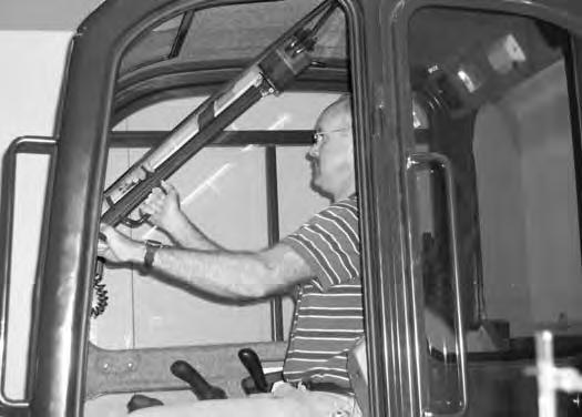
Front Window
Figure OI-67
Open the front window and exit [Figure OI-67].
NOTE:If the excavator has a Special Applications Kit installed, the front window is NOT an emergency exit.
Attachments
Installing And Removing The Attachment (Hydraulic X-Change)
Installation
NOTE: Installation and removal of the bucket is shown. The procedure is the same for other attachments. Disconnect any hydraulic lines that are operated by hydraulic power before removing any attachments (breaker, auger, etc).
Warning
Never use attachments or buckets which are not approved by Bobcat Company. Buckets and attachments for safe loads of specified densities are approved for each model. Unapproved attachments can cause injury or death.
W-2052-0500
Warning
Both hydraulic pins must be fully extended through the attachment mounting holes and locked with both retainer pins and clips. Failure to fully engage and lock hydraulic pins can allow attachment to come off and cause serious injury or death.

W-2507-0706
Start the engine.
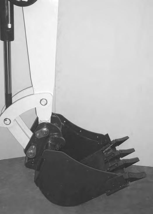
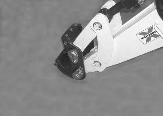
Swing the excavator arm fully to the left [Figure OI-68] (for better operator visibility when connecting attachments).


ATTACHMENTS (CONT’D)
Installing And Removing The Attachment (Hydraulic X-Change) (Cont’d)
Installation (Cont’d)
Raise the boom and extend (curl in) the bucket cylinder until the X-Change contacts the back of the attachment [Figure OI-72]
With the arm vertical, lower the boom until the hooks (Item 1) of the bucket disengage the X-Change pins (Item 2) and the plate (Item 3) [Figure OI-72] fully engages into the bucket crossmember.

Warning
Keep all bystanders 20 feet (6 m) away from equipment when operating. Contact with moving parts, a trench cave-in or flying objects can cause injury or death.
Press and hold the X-Change switch (Item 1) [Figure OI73] to the left and FULLY EXTEND the hydraulic pins.

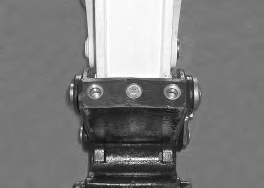
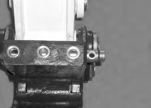
Check that both hydraulic pins (Item 1) [Figure OI-87] are fully engaged to secure the attachment.
Warning
Both hydraulic pins must be fully extended through the attachment mounting holes and locked with both retainer pins and clips. Failure to fully engage and lock hydraulic pins can allow attachment to come off and cause serious injury or death.

ATTACHMENTS (CONT’D)
Installing And Removing The Attachment (Hydraulic X-Change) (Cont’d)
Installation (Cont’d)
Stop the engine.
Install retainer pin (Item 1) and clips (Item 2) [Figure OI75] and [Figure OI-76] into each hydraulic pin (both sides).
Warning
Both hydraulic pins must be fully extended through the attachment mounting holes and locked with both retainer pins and clips. Failure to fully engage and lock hydraulic pins can allow attachment to come off and cause serious injury or death.
W-2507-0706
Removal
NOTE: Removal and installation of the bucket is shown. The procedure is the same for other attachments. Disconnect any hydraulic lines that are operated by hydraulic power before removing any attachments (breaker, auger, etc).
Warning
Keep all bystanders 20 feet (6 m) away from equipment when operating. Contact with moving parts, a trench cave-in or flying objects can cause injury or death.
W-2119-0788
Park the excavator on a flat level surface. Put the attachment on the ground.
Stop the engine.
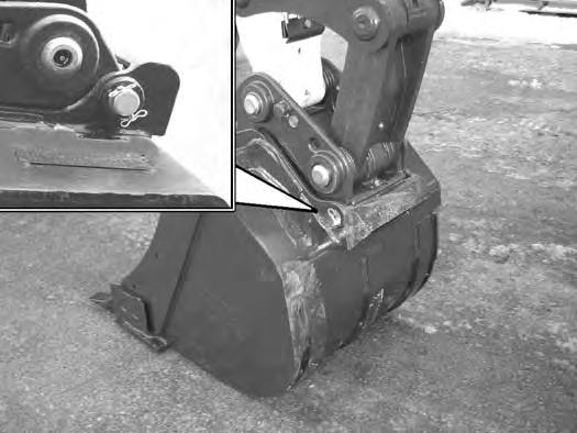
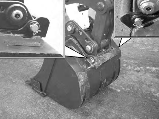
Remove retainer pin (Item 1) and retainer clips (Item 2) [Figure OI-75] and [Figure OI-77] from the hydraulic pin (both sides).

ATTACHMENTS (CONT’D)
Installing And Removing The Attachment (Hydraulic X-Change) (Cont’d)
Removal (Cont’d)
Install both retainer pins (Item 1) and clips (Item 2) [Figure OI-78] in the storage location.
Raise the boom and retract the bucket cylinder until the X-Change pins (Item 1) engage the attachment hooks (Item 2) [Figure OI-80] on the bucket.
Start the engine.
Press and hold the X-Change switch (Item 1) [Figure OI79] on the left console to the right to FULLY RETRACT the hydraulic pins.
Fully retract the bucket cylinder (bucket dump).
Lower the boom and arm until the attachment is on the ground and the X-Change pins are disengaged from the attachment hooks.
Move the arm toward the excavator until the X-Change pins are clear of the attachment [Figure OI-81]


ATTACHMENTS (CONT’D)
Installing And Removing The Attachment (Pin-On XChange)
Installation
Warning
Never use attachments or buckets which are not approved by Bobcat Company. Buckets and attachments for safe loads of specified densities are approved for each model. Unapproved attachments can cause injury or death.
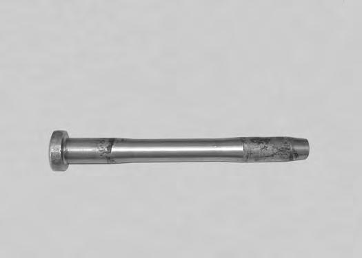
Inspect the pin (Item 1) [Figure OI-82] for wear or damage. Replace the pin as needed.
Apply a light coat of grease to the ends of the pin (Item 2) [Figure OI-82].
ATTACHMENTS (CONT’D)
Installing And Removing The Attachment (Pin-On XChange) (Cont’d)
Installation (Cont’d)
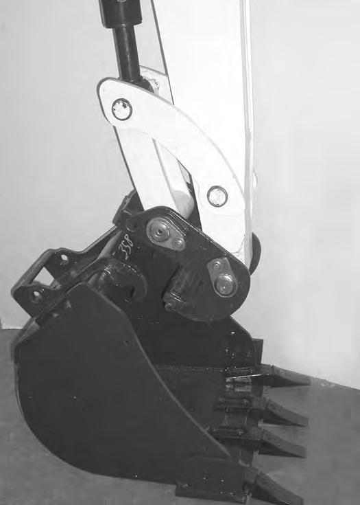
Raise the boom until the pins (Item 1) engage the hooks (Item 2) [Figure OI-84] on the bucket.
Raise the boom and extend the bucket cylinder until the X-Change contacts the attachment back [Figure OI-85]
With the arm vertical, lower the boom until the hooks (Item 1) of the bucket disengage the pins (Item 2) of the X-Change and the plate (Item 3) [Figure OI-85] fully engages in the bucket crossmember.

Warning
Keep all bystanders 20 feet (6 m) away from equipment when operating. Contact with moving parts, a trench cave-in or flying objects can cause injury or death.
ATTACHMENTS (CONT’D)
Installing And Removing The Attachment (Pin-On XChange) (Cont’d)

Installation (Cont’d)
Stop the engine. Turn the start key to the ON position and move both hydraulic control levers to relieve hydraulic pressure.
Drive the pin (Item 1) [Figure OI-86] through the bucket mount and X-Change.
Install the retainer pin (Item 1) [Figure OI-87]
Check for proper installation.
Lift the attachment and fully extend and retract the bucket cylinder.
ATTACHMENTS (CONT’D)
Installing And Removing The Attachment (Pin-On XChange) (Cont’d)

Removal
Use the pin on X-Change when installing new attachments that are equipped with the pin on X-Change bracket.
NOTE: Removal and installation of the bucket is shown. The procedure is the same for other attachments. Disconnect any hydraulic lines that are operated by hydraulic power before removing any attachments (breaker, auger, etc).
Warning
Never use attachments or buckets which are not approved by Bobcat Company. Buckets and attachments for safe loads of specified densities are approved for each model. Unapproved attachments can cause injury or death.
W-2052-0500
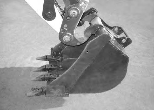
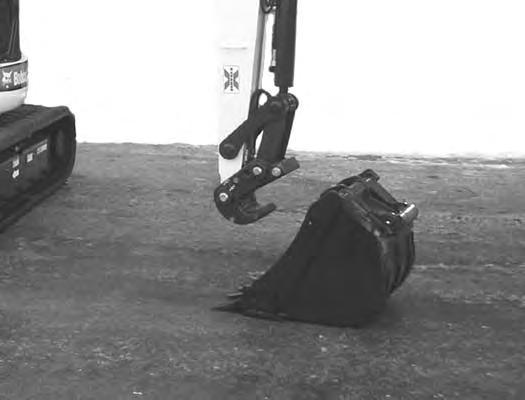
Park the excavator on a flat level surface. Put the bucket on the ground [Figure OI-88]
With the engine off, turn the start key to the ON position and move both hydraulic control levers to relieve hydraulic pressure.
ATTACHMENTS (CONT’D)
Installing And Removing The Attachment (Pin-On XChange) (Cont’d)


Removal (Cont’d)
Warning
Wear safety glasses to prevent eye injury when any of the following conditions exist:
•When fluids are under pressure.
•Flying debris or loose material is present.
•Engine is running.
•Tools are being used.
Start the engine, raise the boom approximately one foot and retract the bucket cylinder until the X-Change pins (Item 1) engage the hooks (Item 2) [Figure OI-91] on the bucket.
ATTACHMENTS (CONT’D)
Installing And Removing The Attachment (Pin-On XChange) (Cont’d)
ATTACHMENTS (CONT’D)
Installing And Removing The Attachment (Bolt-On XChange)
Installation
Use the bolt on X-Change components when installing older attachments that do not have the pin retention provision. (See your Bobcat dealer for the required Bolt-On X-Change components.)
NOTE: Removal and installation of the bucket is shown. The procedure is the same for other attachments. Disconnect any hydraulic lines that are operated by hydraulic power before removing any attachments (breaker, auger, etc.).
Warning
Never use attachments or buckets which are not approved by Bobcat Company. Buckets and attachments for safe loads of specified densities are approved for each model. Unapproved attachments can cause injury or death.

Fully retract the bucket cylinder and lower the arm to the ground [Figure OI-93]
With the engine off, turn the start key to the ON position and move both hydraulic control levers to relieve hydraulic pressure.
ATTACHMENTS (CONT’D)
Installing And Removing The Attachment (Bolt-On XChange) (Cont’d)
Installation (Cont’d)
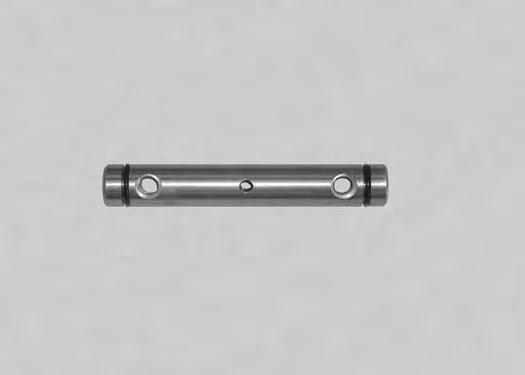
Install the pin (Item 1) in the X-Change. Orientate the bolt holes (Item 2) [Figure OI-96] as shown.
Start the engine and move the arm toward the bucket. Raise the boom until the pins (Item 1) engage the hooks (Item 2) [Figure OI-98] on the bucket.
ATTACHMENTS (CONT’D)
Installing And Removing The Attachment (Bolt-On XChange) (Cont’d)

Installation (Cont’d)
Figure OI-99
Raise the boom, and extend the bucket cylinder until the bucket is in the position shown [Figure OI-99].
With the arm vertical, lower the boom until the hooks (Item 1) of the bucket disengage the pins (Item 2) of the X-Change and plate (Item 3) [Figure OI-99] engages in the bucket crossmember.
Stop the engine. Turn the start key to the ON position and move both hydraulic control levers to relieve hydraulic pressure.
Warning
Keep all bystanders 20 feet (6 m) away from equipment when operating. Contact with moving parts, a trench cave-in or flying objects can cause injury or death.
W-2119-0788
ATTACHMENTS (CONT’D)
Installing And Removing The Attachment (Bolt-On XChange) (Cont’d)
Installation (Cont’d)
Figure OI-101
Install
Tighten the bolts to 130 ft.-lb. (177 N•m) torque. Retorque the bolts after every eight hours of operation.

Check for proper installation.
Lift the attachment and fully extend and retract the bucket cylinder.
Warning
Keep all bystanders 20 feet (6 m) away from equipment when operating. Contact with moving parts, a trench cave-in or flying objects can cause injury or death.
W-2119-0788
ATTACHMENTS (CONT’D)
Installing And Removing The Attachment (Bolt-On XChange) (Cont’d)
Removal
Park the excavator on a flat, level surface. Put the bucket on the ground [Figure OI-102].
With the engine off, turn the start key to the ON position and move both hydraulic control levers to relieve hydraulic pressure.
Start the engine, raise the boom approximately one foot and extend the bucket cylinder until the X-Change pins (Item 1) engage the hooks (Item 2) [Figure OI-104] on the bucket.
ATTACHMENTS (CONT’D)
Installing And Removing The Attachment (Bolt-On XChange) (Cont’d)
Removal (Cont’d)
ATTACHMENTS (CONT’D)
Installing And Removing The Attachment (Pin-On Attachment)
Installation
Warning
AVOID INJURY OR DEATH
Stop the machine on a firm flat surface. When removing or installing attachments (such as a bucket), always have a second person in the operator’s seat, give clear signals and work carefully.
W-2140-0189
Figure OI-106
Install the arm into the bucket and align the mounting hole.
Install the pin (Item 1) [Figure OI-106] and washers.
Install the link (Item 2) in the bucket and align the mounting hole. Install the pin (Item 3) [Figure OI-106] and washers


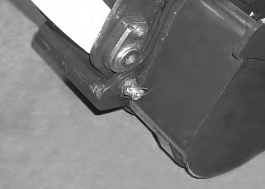
Install the two retainer pins (Item 1) [Figure OI-107]. Install grease in the grease fittings.
Removal
Park the excavator on a flat surface and lower the bucket fully.
Remove the two retainer pins (Item 1) [Figure OI-107]
Remove the washers and pins (Item 1 & 3) [Figure OI106].
Do not damage the dust seals in the arm.
Warning
Never use attachments or buckets which are not approved by Bobcat Company. Buckets and attachments for safe loads of specified densities are approved for each model. Unapproved attachments can cause injury or death.
W-2052-0500
OPERATING PROCEDURE Inspect The Work Area
Before beginning operation, inspect the work area for unsafe conditions.
Look for sharp drop-offs or rough terrain. Have underground utility lines (gas, water, sewer, irrigation, etc.) located and marked.
Remove objects or other construction material that could damage the excavator or cause personal injury.
Lowering The Work Equipment (Engine STOPPED)
The hydraulic control levers control the movement of the boom, arm, bucket and upperstructure slew functions.
The console must be in the locked down position, and the key switch in the ON position.
Use the control lever to lower the boom.
Operating On Public Roads
When operating on a public road or highway, always follow local regulations. For example: A slow moving vehicle (SMV) sign, or direction signals may be required.
Check with utility companies for underground electrical, water, gas lines, etc. Work slowly in areas of underground utilities.
Run the engine at low idle speed to warm the engine and hydraulic system before operating the excavator.
Important
[Figure
NOTE: If the engine stops, the boom/bucket (attachments) can be lowered to the ground using hydraulic pressure in the accumulator.
The control console(s) must be in the locked down position, and the key switch in the ON position.
Use the control lever to lower the boom.
Lower the control console(s) to engage the hydraulic control functions of the joysticks [Figure OI-108]

OPERATING PROCEDURE (CONT’D)
Lifting A Load
Do not exceed the Rated Lift Capacity. (See LIFT CHART on Page MST-4.)
Warning
AVOID INJURY OR DEATH
Do not exceed rated lift capacity. Excessive load can cause tipping or loss of control.
W-2374-0500
Extend the bucket cylinder completely and lower the boom to the ground. Stop the engine.
Wrap the chain assembly around the bucket mounting plate.
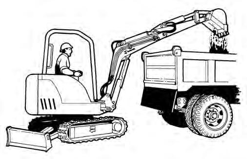
The optional lifting clamp attachment gives the excavator a wider range of use and mobility for debris removal [Figure OI-110]
The lifting clamp cylinder is operated by the auxiliary hydraulic system.
The lifting clamp cylinder must be fully retracted when the machine is being used for excavating.
The lift capacities are reduced by 270 lb. (122 kg) if the excavator is equipped with the optional lifting clamp.
Warning
AVOID INJURY OR DEATH
Make sure the load is evenly weighted and centered on the lifting chain, and is secured to prevent the load from shifting [Figure OI-109].

Lift and position the load. Once the load is in position and tension is removed from the lift chain (secondary lift system), remove the secondary lift system.
Check area to be excavated for overhead or underground lines such as electrical, gas, oil, water, etc. CALL 1-888-258-0808 and consult local utilities before digging. Extreme caution must be used in areas where utility lines are present.
W-2116-0903
OPERATING PROCEDURE (CONT’D)
Excavating
Lower the blade to provide stability.
Figure OI-111
Extend the arm, lower the boom, and open the bucket [Figure OI-111].
Raise the boom, retract the arm and curl the bucket [Figure OI-113]
Rotate the upperstructure.
NOTE: Do not allow the bucket teeth to contact the ground when swinging the upperstructure.
Warning
Keep all bystanders 20 feet (6 m) away from equipment when operating. Contact with moving parts, a trench cave-in or flying objects can cause injury or death.
Retract the arm, while lowering boom and curling the bucket [Figure OI-112].
OPERATING PROCEDURE (CONT’D)
Excavating (Cont’d)
Important
Avoid operating hydraulics over relief pressure. Failure to do so will overheat hydraulic components. I-2220-0503
Do not dig under the excavator [Figure OI-115]
Do not use the bucket as a breaker or pile driver. It is better to excavate hard or rocky ground after breaking it with other equipment. This will reduce damage to the excavator.
Do not move the excavator while the bucket is in the ground.