
10 minute read
INSTRUMENTS AND CONSOLES (CONT’D)


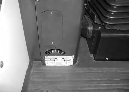
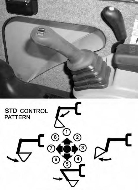
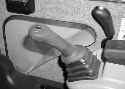
STD / ISO Selector Valve
Figure OI-5
The joystick hydraulic function can be switched from Standard control pattern to ISO control pattern [Figure OI-5]
Move the lever (Item 1) to the right (Item 2) to select STANDARD Control Pattern. Move to the left (Item 3) to select ISO Control Pattern [Figure OI-5]
Upperstructure Slew Brake
There is not a mechanical upperstructure slew lock to engage or disengage. This Excavator is equipped with an automatically applied slew brake integrated into the slew motor.
When the upperstructure slew circuit is engaged, hydraulic pressure unlocks the slew motor.
When the upperstructure slew circuit is disengaged, spring pressure applies the internal slew motor brake.
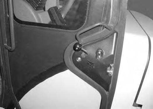
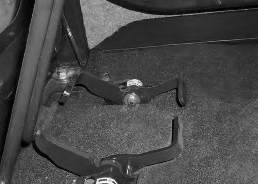
Raising And Lowering The Console
Raise the console before exiting the cab.
Figure OI-6
Pull up on the release handle [Figure OI-6]. The lift spring will assist in raising the console.
Lower the console before operating the excavator.
Push down on the console [Figure OI-6] until the latch is engaged.
NOTE: When the console is raised, the hydraulic and traction system functions are locked and will not operate.
If the engine stops, the boom/bucket (attachments) can be lowered to the ground using hydraulic pressure in the accumulator.
The control console must be in the locked down position, and the key switch in the ON position.
INSTRUMENTS AND CONSOLES (CONT’D)

Two-Speed Travel

OPERATOR CANOPY (ROPS / TOPS)
Description
The excavator has an operator canopy (ROPS/TOPS) (Roll Over Protective Structure/Tip Over Protective Structure) as standard equipment. The ROPS/TOPS meets ISO 3471 and ISO 12117.
Both the cab and canopy provide operator protection if the excavator is tipped over. The seat belt must be worn for ROPS /TOPS protection.
Warning
Never modify operator cab by welding, grinding, drilling holes or adding attachments unless instructed to do so by Bobcat Company. Changes to the cab can cause loss of operator protection from rollover and falling objects, and result in injury or death.
W-2069-0200
OPERATOR CAB (ROPS / TOPS)
Description
The excavator has an optional operator cab (ROPS/ TOPS) (Roll Over Protective Structure/Tip Over Protective Structure). The ROPS/TOPS meets ISO 3471 and ISO 12117.
An enclosed cab (ROPS/TOPS) is an Option or can be installed as a Field Accessory.
Both the cab and canopy provide operator protection if the excavator is tipped over. The seat belt must be worn for ROPS /TOPS protection.
Warning
Never modify operator cab by welding, grinding, drilling holes or adding attachments unless instructed to do so by Bobcat Company. Changes to the cab can cause loss of operator protection from rollover and falling objects, and result in injury or death.
W-2069-0200
OPERATOR CAB (ROPS / TOPS) (CONT’D)
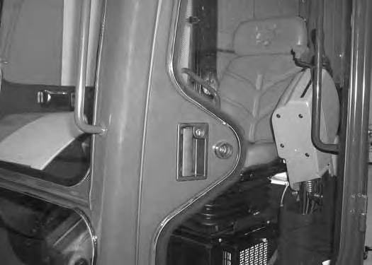
Cab Door
Early Models
The cab door (Item 1) [Figure OI-9] can be locked with the same key as the starter switch (if equipped).

Later Models
Push the door all the way open until the latch engages to hold the door in the open position.
Firmly pull the door away from the cab to disengage the latch and close the door [Figure OI-10]

From inside the cab, open the door using handle (Item 1) [Figure OI-10]
The cab door can be locked (Item 1) [Figure OI-11] with the same key as the starter switch.
Push the door all the way open (Item 2) [Figure OI-11] until the latch engages to hold the door in the open position.
When the door is in the open position, push down on the latch (Item 1) [Figure OI-12] and close the door.
From inside the cab, open the door using handle (Item 2) [Figure OI-12].
OPERATOR CAB (ROPS / TOPS) (CONT’D)

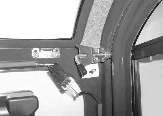
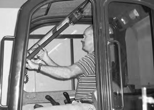
Front Window
Opening The Front Window
Retract the two top window latch pins (Item 1) [Figure OI-13]

Use both window grab handles to pull the top of the window in [Figure OI-15]
Continue moving the window in and up over the operator’s head until the window is fully raised.
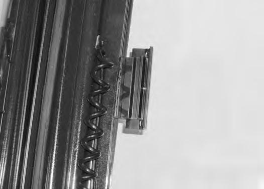
Turn the two top latches (Item 1) [Figure OI-14] to the unlocked position.
When the window is fully raised, the latch (Item 1) will close on the bracket. Turn the two top latches (Item 2) [Figure OI-16] to the locked position.
OPERATOR CAB (ROPS / TOPS) (CONT’D)

Front Window (Cont’d)
Closing The Front Window
Support the window while releasing both window latch pins and placing the pins in the unlocked position [Figure OI-16 on Page OI-10]
Support the window using the left grab handle and pull down on the latch (Item 1) [Figure OI-16 on Page OI-10] to release the window.
Use both window grab handles to pull the window down [Figure OI-15 on Page OI-10]
Rotate the top latches (Item 1) [Figure OI-14 on Page OI-10] to the locked position (Item 1) [Figure OI-13 on Page OI-10].
Front Wiper
Figure OI-17
The front window is equipped with a wiper (Item 1) [Figure OI-17] and washer.
Window Washer Reservoir
Figure OI-18
The window washer reservoir (Item 1) [Figure OI-18] is located under the right side cover.
OPERATOR CAB (ROPS / TOPS) (CONT’D)
Right Side Window

Opening The Right Rear Window
Figure OI-19
Pull forward on the latch / handle (Item 1) [Figure OI-19]

Opening The Right Front Window
Pull the latch / handle (Item 1) [Figure OI-20] forward to open the window.
Closing The Right Rear Window
Push the handle back to close the window.
Pull back on the latch / handle (Item 1) [Figure OI-21]
Pull the latch / handle (Item 1) [Figure OI-22] back to open the window.
Closing The Right Front Window
Push the handle forward to close the window.

OPERATOR CAB (ROPS / TOPS) (CONT’D)


Heating, Ventilation And Air Conditioning Duct
NOTE: The air conditioner duct can be ordered and used on heater models.
There are two air ducts that the operator can choose to install.
The large duct (Item 1) [Figure OI-24] is standard for models that have air conditioner available.
NOTE: This duct (Item 1) [Figure OI-24] can be removed for improved operator visibility.
Installation
Remove the screw and pull straight up to remove the duct (Item 1) [Figure OI-23].

Travel Controls
Description
The travel control levers control the movement of the excavator.
Forward And Reverse Travel
NOTE: The following procedures describe forward, reverse, left & right as seated in the operator’s seat.
Turning Right Turn
Figure OI-27
Right Turn (Forward)
Push the left steering lever forward to turn right [Figure OI-27] while traveling forward.
Right Turn (Reverse)
Put the blade so that it is at the front of the machine (as you sit in the operator’s seat). Slowly move both steering levers* (Item 1) [Figure OI-26] forward for forward travel; backward for reverse travel.
* Travel can also be controlled with foot pedals (Item 2) [Figure OI-26]. Pivot the heel of the pedals forward for additional space on the floor.
Warning
AVOID INJURY OR DEATH
•Check the blade location before traveling. When the blade is to the rear, operate the steering levers/foot pedals in the opposite direction to when the blade is in the front.
•Move the steering levers/foot pedals slowly. Abrupt lever motion will cause the machine to jerk.

W-2235-0396
Pull the left steering lever backward to turn right while traveling backward [Figure OI-28]
TRAVEL CONTROLS (CONT’D)
Turning (Cont’d)
Counter - Rotation Right Turn
Figure OI-29
Push the left steering lever forward and pull the right steering lever backward [Figure OI-29].


Left Turn
Figure OI-30
Push the right steering lever forward to turn left [Figure OI-30] while traveling forward.
Pull the right steering lever backward to turn left while traveling backward [Figure OI-31]
Counter - Rotation Left Turn
Figure OI-32
Counter
B-19991
Push the right steering lever forward and pull the left steering lever backward [Figure OI-32].
Hydraulic Controls
Description
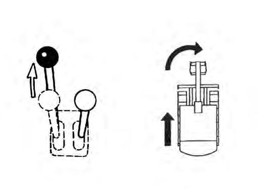
The work equipment (boom, arm, bucket, and upperstructure slew) is operated by using the left and right control levers (joysticks). These joysticks can be used in either a STANDARD Control Pattern [Figure OI33] & [Figure OI-34] or in the ISO Control Pattern [Figure OI-35] & [Figure OI-36].
STANDARD Control Pattern
Left Control Lever (Joystick)
Figure OI-33
The left lever (joystick) is used to operate the arm and slew the upperstructure [Figure OI-33]
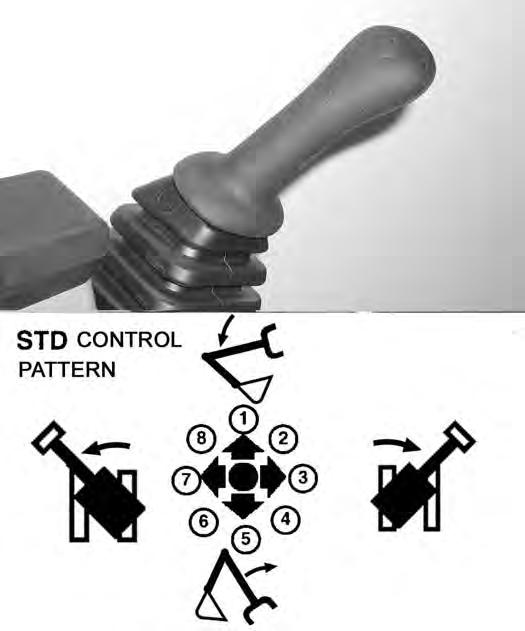
1.Boom lower.
2.Boom lower and slew right.
3.Slew right.
4.Boom raise and slew right.
5.Boom raise.
6.Boom raise and slew left.
7.Slew left.
8.Boom lower and slew left.
Important
Before slewing the upperstructure, make sure the slew lock is disengaged.
I-2051-0905
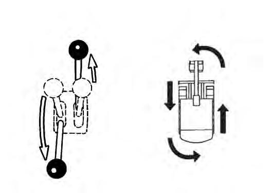
Right Control Lever (Joystick)
1.Arm out.
2.Arm out and bucket dump.
3.Bucket dump.
4.Arm in and bucket dump.
5.Arm in.
6.Arm in and bucket curl.
7.Bucket curl.
8.Arm out and bucket curl.
Warning
AVOID INJURY OR DEATH
Before leaving the machine:
•Lower the work equipment to the ground.
•Lower the blade to the ground.
•Stop the engine & remove the key.
W-2196-0595
HYDRAULIC CONTROLS (CONT’D)
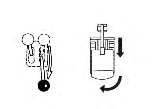
ISO Control Pattern
Left Control Lever (Joystick)
Figure OI-35
The left lever (joystick) is used to operate the arm and slew the upperstructure [Figure OI-33]
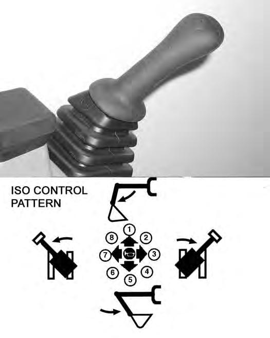
1.Arm out.
2.Arm out and slew right.
3.Slew right.
4.Arm in and slew right.
5.Arm in.
6.Arm in and slew left.
7.Slew left.
8.Arm out and slew left.
Right Control Lever (Joystick)
The right lever (joystick) is used to operate the boom and bucket [Figure OI-34]

1.Boom lower.
2.Boom lower and bucket dump.
3.Bucket dump.
4.Boom raise and bucket dump.
5.Boom raise.
6.Boom raise and bucket curl.
7.Bucket curl.
8.Boom lower and bucket curl.
Warning
AVOID INJURY OR DEATH
Before leaving the machine:
•Lower the work equipment to the ground.
•Lower the blade to the ground.
•Stop the engine & remove the key.
W-2196-0595
HYDRAULIC CONTROLS (CONT’D)
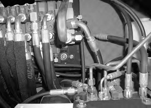
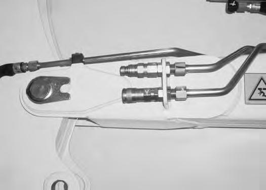
Quick Couplers WARNING
Avoid Burns
Hydraulic fluid, tubes, fittings and quick couplers can get hot when running machine and attachments. Be careful when connecting and disconnecting quick couplers.
To Disconnect:
Figure OI-38
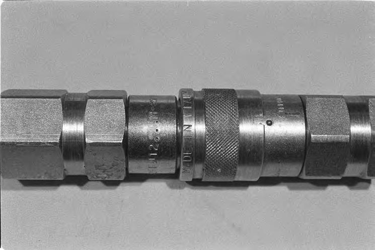
Excavators and attachments use flush faced couplers (Item 1) [Figure OI-37]
To Connect:
Remove any dirt or debris from the surface of both the male and female couplers, and from the outside diameter of the male coupler. Visually check the couplers for corroding, cracking, damage, or excessive wear, if any of these conditions exist, the coupler(s) (Item 1) [Figure OI37] must be replaced.
Install the male coupler into the female coupler. Full connection is made when the ball release sleeve slides forward on the female coupler.
Hold the male coupler (Item 1). Retract the sleeve (Item 2) [Figure OI-38] on the female coupler until the couplers disconnect.
HYDRAULIC CONTROLS (CONT’D)
Auxiliary Hydraulics
Figure OI-39
Press the Auxiliary Hydraulics button on the right console (Item 1) [Figure OI-39].
Figure OI-40
Move the switch (Item 1) [Figure OI-40] on the right control lever to the right or left to direct fluid flow to an attachment such as a breaker or hydraulic clamp.
Press the switch (Item 2) [Figure OI-40] on the front of the handle to provide constant flow to the female coupler.
NOTE: Pressing the switch (Item 1) [Figure OI-40] to the left while pressing the switch on the front of the handle will provide constant flow to the male coupler.

Press the switch (Item 2) [Figure OI-40] a second time to stop auxiliary flow to the quick couplers.
Relieve Hydraulic Pressure (Excavator And Attachment)
Excavator:
Put the attachment flat on the ground.
Stop the engine and turn the key to ON (Standard) or press ENTER CODE Button (Keyless).
NOTE: The left console must be fully lowered for relieving hydraulic pressure.
Press AUX HYD Button (Item 1) [Figure OI-39] and then move the switch (Item 1) [Figure OI-40] to the right and left several times.

Attachments:
•Follow procedure above to release pressure in excavator.
•Connect male coupler from attachment to female coupler of excavator then repeat procedure above. This will release pressure in the attachment.
•Connect the female coupler from the attachment.
Hydraulic pressure in the auxiliary hydraulic system can make it difficult to engage quick couplers to an attachment.
Return To Tank Valve (If Equipped)
The return to tank valve is located under the right side cover.
Remove
Pull the spool out and install the spool lock (Item 1) [Figure OI-41] for two way hydraulic auxiliary flow operation.
BLADE CONTROL LEVER Operation

Figure OI-42
Pull the lever backward to raise the blade (Item 1) [Figure OI-42]
Push the lever forward to lower the blade (Item 2) [Figure OI-42].
Push the lever (Item 3) [Figure OI-42] forward until the lever is in the locked position to put the blade in the float position.
Pull the lever backward to unlock from the float position.
NOTE: Keep the blade lowered when digging to help stabilize machine.
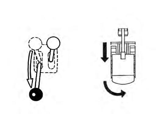
BOOM SWING PEDAL Operation
Figure OI-43
Release the pedal lock and pivot the heel of the pedal to the rear (Item 1) [Figure OI-43]
Push the toe of the pedal (Item 2) to swing the boom to the right; push the heel (Item 1)[Figure OI-43] to swing the boom to the left.
Figure OI-44
B-19937
NOTE: The purpose of the boom swing pedal is to offset the boom with respect to the upperstructure for digging close to a structure [Figure OI-44].
Daily Inspection
DAILY INSPECTION (CONT’D)
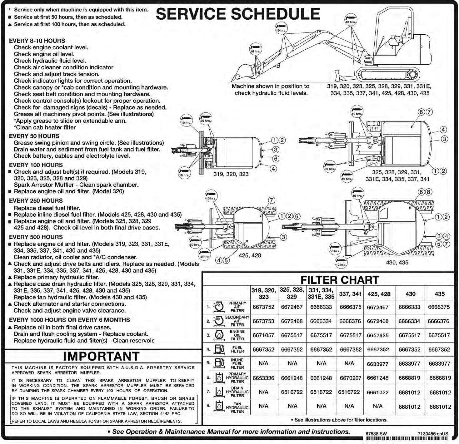
Daily Inspection And Maintenance
Maintenance work must be done at regular intervals. Failure to do so will result in excessive wear and early failures. The Service Schedule [Figure OI-45] is a guide for correct maintenance of the Bobcat Excavator. It is located inside the rear door of the excavator and also in this manual.
Check the following items before each day of operation:
•Operator Canopy or Cab (ROPS/TOPS) and mounting hardware.
•Seat belt and mounting hardware.
•Damaged decals, replace as needed.
•Check control console lockout.
•Air cleaner and intake hoses/clamps.
•Engine oil level and engine for leaks.
•Hydraulic fluid level and system for leaks.
•Grease all pivot points.
•Cylinder and attachment pivot points.
•Track tension.
•Repair broken and loose parts.
Warning
Operator must have instructions before operating the machine. Untrained operators can cause injury or death.
W-2001-0502
Fluids such as engine oil, hydraulic fluid, coolants, etc. must be disposed of in an environmentally safe manner. Some regulations require that certain spills and leaks on the ground must be cleaned in a specific manner. See local, state, and federal regulations for correct disposal.
Important
Pressure Washing Decals
•Never direct the stream at a low angle toward the decal that could damage the decal causing it to peel from the surface.
•Direct the stream at a 90 degree angle and at least 12 inches (300 mm) from the decal. Wash from the center of the decal toward the edges.
I-2226-0104


