13 minute read
ELECTRICAL SYSTEM


Description
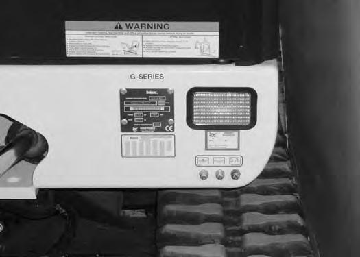
Figure PM-34
The excavator has a 12 volt, negative ground electrical system. The electrical system is protected by fuses located under the right side cover of the excavator (Item 1) [Figure PM-34]. The fuses will protect the electrical system when there is an electrical overload. The reason for the overload must be found before starting the engine again.
The battery cables must be clean and tight. Check the electrolyte level in the battery. Add distilled water as needed. Remove acid or corrosion from the battery and cables with a sodium bicarbonate and water solution.
Put Battery Saver P/N 6664458 or grease on the battery terminals and cable ends to prevent corrosion.
Warning
AVOID INJURY OR DEATH
Batteries contain acid which burns eyes and skin on contact. Wear goggles, protective clothing and rubber gloves to keep acid off body.
In case of acid contact, wash immediately with water. In case of eye contact get prompt medical attention and wash eye with clean, cool water for at least 15 minutes.
If electrolyte is taken internally drink large quantities of water or milk! DO NOT induce vomiting. Get prompt medical attention.
W-2065-0807
Fuse And Relay Location / Identification

A decal is inside the cover to show location and amp ratings.
Remove the cover to check or replace the fuses and relays.
Figure PM-35
The location and sizes are shown below and [Figure PM35]
Always replace using the same type and capacity.
ELECTRICAL SYSTEM (CONT’D)
Battery Maintenance
Open the right side cover.
The battery cables must be clean and tight [Figure PM37]. Remove acid or corrosion from the battery and cables using a sodium bicarbonate and water solution. Cover the battery terminals and cable ends with battery saver grease to prevent corrosion.

Check for broken or loose connections.
If the battery cables are removed for any reason, disconnect the negative (-) cable first. When installing the battery cables, make the last connection the negative (-) cable to the battery.
The original equipment battery is maintenance free. If a replacement battery is installed, check the electrolyte level in the battery.

If the electrolyte level is lower than 0.50 inch (13 mm) above the plates, add distilled water only.

Warning
Batteries contain acid which burns eyes and skin on contact. Wear goggles, protective clothing and rubber gloves to keep acid off body.
In case of acid contact, wash immediately with water. In case of eye contact get prompt medical attention and wash eye with clean, cool water for at least 15 minutes.
If electrolyte is taken internally drink large quantities of water or milk! DO NOT induce vomiting. Get prompt medical attention.
ELECTRICAL SYSTEM (CONT’D)
Using A Booster Battery (Jump Starting)
Important
If jump starting the excavator from a second machine:
When jump starting the excavator from a battery installed in a second machine, make sure the engine is NOT running while using the glow plugs. High voltage spikes from a running machine can burn out the glow plugs.
I-2060-0906
If it is necessary to use a booster battery to start the engine, BE CAREFUL! There must be one person in the operator’s seat and one person to connect and disconnect the battery cables.
Be sure the key switch is OFF. The booster battery must be 12 volt.
Open the tailgate.
Figure PM-38
Connect one end of the first cable to the positive (+) terminal of the booster battery. Connect the other end of the same cable to the positive (+) terminal (Item 1) [Figure PM-38] of the excavator starter.
Connect one end of the second cable to the negative (-) terminal of the booster battery. Connect the other end of the same cable to the negative excavator cable (Item 2) [Figure PM-38] where it is fastened to the frame.
Start the engine. After the engine has started, remove the ground (-) cable first (Item 2) [Figure PM-38].
Disconnect the cable from the excavator starter (Item 1) [Figure PM-38]
NOTE: (See Cold Temperature Starting on Page OI27).
Important
Damage to the alternator can occur if:
•Engine is operated with battery cables disconnected.

•Battery cables are connected when using a fast charger or when welding on the excavator. (Remove both cables from the battery.)
•Extra battery cables (booster cables) are connected wrong.
I-2222-0903
Warning
AVOID INJURY OR DEATH
Batteries contain acid which burns eyes and skin on contact. Wear goggles, protective clothing and rubber gloves to keep acid off body.
In case of acid contact, wash immediately with water. In case of eye contact get prompt medical attention and wash eye with clean, cool water for at least 15 minutes.
If electrolyte is taken internally drink large quantities of water or milk! DO NOT induce vomiting. Get prompt medical attention.
W-2065-0807
ELECTRICAL SYSTEM (CONT’D)
Removing And Installing The Battery

Open the right side cover.
Figure PM-39
Warning
AVOID INJURY OR DEATH
Batteries contain acid which burns eyes and skin on contact. Wear goggles, protective clothing and rubber gloves to keep acid off body.
In case of acid contact, wash immediately with water. In case of eye contact get prompt medical attention and wash eye with clean, cool water for at least 15 minutes.
If electrolyte is taken internally drink large quantities of water or milk! DO NOT induce vomiting. Get prompt medical attention.
W-2065-0807
Disconnect the negative (-) cable (Item 1) [Figure PM39] first.
Disconnect the positive (+) cable (Item 2) [Figure PM39]
Remove the bolts (Item 3) [Figure PM-39] and remove the hold down clamp.
Remove the battery.
Always clean the terminals and the cable ends, even when installing a new battery.
Install the battery. Install the hold down clamp and tighten the bolts.
Connect the battery cables. Connect the negative (-) cable (Item 1) [Figure PM-39] last to prevent sparks.
Hydraulic System
Checking And Adding Hydraulic Oil
Put the machine on a flat level surface.
Retract the arm and bucket cylinders, put the bucket on the ground and lower the blade. Stop the engine.
Open the tailgate.
Figure PM-40
Check the hydraulic fluid level, it must be visible in the sight gauge (Item 1) [Figure PM-40]
Clean the surface around the reservoir (breather) cap and remove the cap from the reservoir (Item 2) [Figure PM-40]
Warning
Always clean up spilled fuel or oil. Keep heat, flames, sparks or lighted tobacco away from fuel and oil. Failure to use care around combustibles can cause explosion or fire which can result in injury or death.
W-2103-1285
Check the condition of the fill strainer screen (Item 1) [Figure PM-41]. Clean or replace as necessary.
Be sure the screen is installed before adding fluid.
Add the correct fluid to the reservoir until it is visible in the sight gauge. (See HYDRAULIC SYSTEM on Page SPEC-26.)


Check the cap and clean as necessary. Replace the cap if damaged.
Install the cap.
Close the tailgate.
Hydraulic Fluid Chart

Figure PM-42
Use the correct hydraulic fluid shown in chart [Figure PM-42].
Add hydraulic fluid as needed to bring the level to the center of sight gauge (Item 1) [Figure PM-40]
Install the oil fill cap.
HYDRAULIC SYSTEM (CONT’D)
Removing And Replacing The Hydraulic Filters
Warning
AVOID INJURY OR DEATH
Always clean up spilled fuel or oil. Keep heat, flames, sparks or lighted tobacco away from fuel and oil. Failure to use care around combustibles can cause explosion or fire which can result in injury or death.

W-2103-0807
See the SERVICE SCHEDULE for the correct service interval. (See SERVICE SCHEDULEon PagePM-5.)
Open the right side cover.
Remove the primary hydraulic filter (Item 1) [Figure PM43].
Clean the housing where the filter gasket makes contact.
Put clean hydraulic fluid on the gasket. Install the new filter and hand tighten only. Use a genuine Bobcat replacement filter.
Remove the case drain filter (Item 2) [Figure PM-43].
Clean the housing where the filter gasket makes contact.
Put clean hydraulic fluid on the gasket. Install the new filter and hand tighten only.
HYDRAULIC SYSTEM (CONT’D)
Removing And Replacing The Hydraulic Fluid
See the SERVICE SCHEDULE for the correct service interval. (See SERVICE SCHEDULEon PagePM-5.)
Warning
Avoid Injury Or Death
Diesel fuel or hydraulic fluid under pressure can penetrate skin or eyes, causing serious injury or death. Fluid leaks under pressure may not be visible. Use a piece of cardboard or wood to find leaks. Do not use your bare hand. Wear safety goggles. If fluid enters skin or eyes, get immediate medical attention from a physician familiar with this injury.
W-2072-0807
Retract the arm and bucket cylinders, lower the bucket to the ground. Stop the engine.
Open the tailgate.
Figure PM-44
Remove the drain plug (Item 1) [Figure PM-44]
Drain the fluid into a container.
Recycle or dispose of the fluid in an environmentally safe manner.
Install the drain plug (Item 1) [Figure PM-44]
Add fluid to the reservoir. (See HYDRAULIC SYSTEMon PagePM-26.)

Open the bleed valve (Item 1) [Figure PM-45] on the hydraulic pump. Close the valve after a steady stream of hydraulic fluid free of any air bubbles drains from the valve. Tighten the bleed valve. DO NOT RUN THE MACHINE WITH THE BLEED VALVE OPEN.
Start the engine and operate the machine through the hydraulic functions. Stop the engine. Check the fluid level and add as needed.

SPARK ARRESTOR MUFFLER Cleaning Procedure
See the SERVICE SCHEDULE for the correct service interval. (See SERVICE SCHEDULE on Page PM-5.)
Warning
Avoid Injury Or Death
When an engine is running in an enclosed area, fresh air must be added to avoid concentration of exhaust fumes. If the engine is stationary, vent the exhaust outside. Exhaust fumes contain odorless, invisible gases which can kill without warning.
W-2050-0807
Warning
Stop engine and allow the muffler to cool before cleaning the spark chamber. Wear safety goggles. Failure to obey can cause serious injury.
W-2011-1285
Warning
Never use machine in atmosphere with explosive dust or gases or where exhaust can contact flammable material. Failure to obey warnings can cause injury or death.
W-2068-1285
Warning
When the engine is running during service, the steering levers must be in neutral.

Failure to do so can cause injury or death.
W-2203-0595
Do not operate the excavator with a defective exhaust system.
Stop the engine. Open the tailgate.
Remove
Start the engine and run for about 10 seconds while a second person, wearing safety glasses, holds a piece of wood over the outlet of the muffler. The carbon deposits will be forced out of the muffler plug hole (Item 1) [Figure PM-46]
Stop the engine. Install and tighten the plug.
Close the tailgate.
Track Tension
NOTE: The wear of the pins and bushings on the undercarriage vary with the working conditions and the different types of soil conditions. It is necessary to inspect track tension and maintain the correct tension. See SERVICE SCHEDULE for the correct service interval. (See SERVICE SCHEDULEon PagePM-5.)

Adjusting
Figure PM-47
Raise one side of the machine (Approximately four inches) using the boom and arm [Figure PM-47].
Raise the blade fully and install jackstands under the blade and track frame (Item 1) [Figure PM-47]. Lower the boom until all machine weight is on the jackstands.

Stop the engine.
Warning
AVOID INJURY
Keep fingers and hands out of pinch points when checking the track tension.
Measure the clearance at the middle track roller. Do not get fingers into pinch points between the track and the track roller. Use a bolt or a dowel of the appropriate size to check the gap between the contact edge of the roller and the top edge of the track guide [Figure PM-48] & [Figure PM-49].
TRACK TENSION (CONT’D)
Adjusting (Cont’d)
Steel Track Clearance
Figure PM-50
Measure the track clearance at the middle track roller. Do not get fingers into pinch points between the track and the track roller. Us a bolt or dowel of the appropriate size to check the gap between the contact edge of the roller and the top edge of the track guide [Figure PM-50]

Steel Track Clearance - 0.680-1.180 in. (17,3-30 mm).

Add grease to the fitting (Item 1) [Figure PM-52] until the track tension is correct.
Loosen the two bolts from the cover (Item 1) [Figure PM51]. Pivot the cover downward.


Use tool MEL1560 (Item 1) [Figure PM-53] to loosen the bleed fitting (Item 2) [Figure PM-52] to release tension from the track.
NOTE: Do not loosen the grease fitting (Item 1) [Figure PM-52].
Repeat the procedure for the other side.
Travel Motor
Checking And Adding Oil
Figure PM-54
Park the excavator on a level surface with the plugs (Items 1 & 2) [Figure PM-54] in the position as shown.
Remove the plug (Item 1) [Figure PM-54]. The lube level must be at the bottom edge of the hole.
Add lubricant (SAE-80W90) through the hole if the lube level is low.
Removing And Replacing Oil
See the SERVICE SCHEDULE for the correct service interval. (See SERVICE SCHEDULEon PagePM-5.)
Park the excavator on a level surface with plugs (Items 1 & 2) [Figure PM-54] in the position shown. Remove both plugs and drain the lubricant into a container.
Warning
Avoid Injury Or Death
Always clean up spilled fuel or oil. Keep heat, flames, sparks or lighted tobacco away from fuel and oil. Failure to use care around combustibles can cause explosion or fire which can result in injury or death.
W-2103-0807
Install the bottom plug (Item 2 [Figure PM-54]). Add lubricant through the top plug hole until the lube level is at the bottom edge of the hole.

Add lubricant (SAE-90W) through the hole if the lube level is low.
Install the plug (Item 1) [Figure PM-54].
Alternator Belt

Belt Adjustment
Open the tailgate.
Figure PM-55
Using a belt tension gauge, measure the belt tension midway between the crankshaft pulley and alternator pulley [Figure PM-55].

Belt tension is as follows:
New belt 107-114 ft.-lb. (145-155 N•m)
Used belt 92-99 ft.-lb. (125-134 N•m)
Figure PM-56
Loosen the nut (Item 1) on the belt idler pulley. Loosen the nut (Item 2) and tighten the bolt (Item 3) [Figure PM56] until the belt tension is correct.
Tighten the nut (Item 1) to 29-37 ft.-lb. (40-50 N•m) torque. Tighten the nut (Item 2) [Figure PM-56] to 15-18 ft.-lb. (20-25 N•m) torque.
X-CHANGE
Inspection And Maintenance
Figure PM-57
Inspect the X-Change for wear or damage. Inspect the XChange pins (Item 1) and hooks (Item 2) [Figure PM-57] (on the attachment) for wear or damage.
Repair or replace damaged parts.
Track Roller And Idler Lubrication
Procedure
The track rollers and idlers require no maintenance. The bearings are a sealed design.

BUCKET Bucket Teeth Removal And Installation
Warning
Wear safety glasses to prevent eye injury when any of the following conditions exist:
•Pressurized fluids and springs or other stored energy components.
•Flying debris or loose material is present.
•Engine is running.
•Tools are being used.
W-2505-0604
Position the bucket so the bucket teeth are at a 30° angle up from the ground for accessibility to the teeth.
Lower the boom until the bucket is fully on the ground. Stop the engine and exit the excavator.
The retaining pin (Item 1) must be installed as shown [notch (Item 2) to the front] for proper fit and tooth retention. The side of the tooth point (Item 3) [Figure PM-58] also shows the correct orientation of the retaining pin.
Installation: Position the new tooth point on the shank and install a new retaining pin. Install the retaining pin until it is flush with the top of the point.

Lubrication Of The Hydraulic Excavator
Lubrication Locations
Lubricate the excavator as specified in the SERVICE SCHEDULE for the best performance of the machine. (See SERVICE SCHEDULEon PagePM-5.)
Always use a good quality lithium based multipurpose grease when lubricating the machine. Apply the lubricant until extra grease shows.


Lubricate the following locations on the excavator EVERY 8-10 HOURS:

5.Boom Swing Pin (2) [Figure PM-60]
6.Boom Swing Pivot (3) [Figure PM-60]
7.Boom Pivot (1) [Figure PM-60]
8.Boom Cylinder Base End (1) [Figure PM-60]
Figure PM-61
Ref Description (# of Fittings)
1.Blade Cylinder Rod End (1) [Figure PM-59]
2.Blade Cylinder Base End (1) [Figure PM-59]
3.Blade Pivots (2) [Figure PM-59]
4.Boom Swing Cylinder Rod End (1) [Figure PM-59]
9.Boom Cylinder Rod End (1) [Figure PM-61]
10.Arm Cylinder Base End (1) [Figure PM-61]
LUBRICATION OF THE HYDRAULIC EXCAVATOR (CONT’D)
Lubrication Locations (Cont’d)
Figure PM-62
11.Arm Cylinder Rod End (1) [Figure PM-62]
12.Arm Pivot (1) [Figure PM-62]
13.Bucket Cylinder Base End (1) [Figure PM-62]
Figure PM-63
14.Bucket Cylinder Rod End (1) [Figure PM-63]
15.Bucket Link Pin (1) [Figure PM-63]
16.Bucket Pivot (3) [Figure PM-63]
17.Bucket Link (2) [Figure PM-63]
18.Boom Swing Cylinder Base End (1) [Figure PM-64]
Lubricate the following locations on the hydraulic excavator EVERY 50 HOURS:

19.Swing Circle (1) [Figure PM-64].
20.Swing Pinion (1) [Figure PM-64]. (Install 3 to 4 pumps of grease then rotate the upperstructure 90°. Install 3 to 4 pumps of grease and again rotate the upperstructure 90°. Repeat this until the slew pinion has been greased at four positions.)

LUBRICATION OF THE HYDRAULIC EXCAVATOR (CONT’D)
Lubrication Locations (Cont’d)
Pivot Pins
Inspection And Maintenance
Figure PM-66
The boom, arm and cylinders pivots (Item 1) have a large pin held in position with a snap ring (Item 2) [Figure PM66]

Check that the snap rings are securely inserted into the grooves on the pins and that the snap rings are not damage. See your Bobcat dealer for replacement parts.

EXCAVATOR STORAGE AND RETURN TO SERVICE Storage
Sometimes it may be necessary to store your Bobcat Excavator for an extend period of time. Below is a list of items to perform before storage.
•Thoroughly clean the excavator including the engine compartment.
•Lubricate the excavator.
•Replace worn or damaged parts.
•Drive the excavator onto planks in a dry protected shelter.
•Lower the boom fully with the bucket flat on the ground.
•Put grease on any exposed cylinder rods.
•Put fuel stabilizer in the fuel tank and run the engine a few minutes to circulate the stabilizer to the pump and fuel injectors.
•Drain and flush the cooling system. Refill with premixed coolant.
•Replace all fluids and filters (engine, hydraulic).
•Replace all filters (i.e.: air cleaner, heater, etc.).
•Put all controls in neutral position.
•Remove the battery. Be sure the electrolyte level is correct then charge the battery. Store it in a cool dry place above freezing temperatures and charge it periodically during storage.
•Cover the exhaust pipe opening.
•Tag the machine to indicate that it is in storage condition.
Return to Service
After the Bobcat Excavator has been in storage, it is necessary to follow a list of items to return the excavator to service.
•Check the engine and hydraulic oil levels; check coolant level.
•Install a fully charged battery.
•Remove grease from exposed cylinder rods.
•Check all belt tensions.
•Be sure all shields and guards are in place.
•Lubricate the excavator.
•Remove cover from exhaust pipe opening.
•Start the engine and let run for a few minutes while observing the instrument panels and systems for correct operation.
•Drive the excavator off of the planks.
•Operate machine, check for correct function.
•Stop the engine and check for leaks. Repair as needed.