39 minute read
EXCAVATOR IDENTIFICATION


AUXILIARY QUICK COUPLERS
ARM CYLINDER LIFT POINT
OPERATOR’S HANDBOOK OPERATOR SEAT With SEAT BELT CONTROL LEVERS (JOYSTICKS)
BUCKET CYLINDER
BOOM
ARM
BOOM CYLINDER
BUCKET LINK
X-CHANGE™
TIE DOWNS/ LIFT POINTS BUCKET
*CANOPY/CAB (ROPS/TOPS)
BLADE CYLINDER
RIGHT SIDE COVER
TIE DOWN
TAILGATE TRACK TRACK
BLADE
TRACK FRAME
UPPERSTRUCTURE
† BUCKET - Several different buckets and other attachments are available from the Bobcat Excavator.
B-19948
● ROPS, TOPS - (Roll Over Protective Structure / Tip Over Protective Structure) as standard equipment. The ROPS/ TOPS meets ISO 3471 and ISO 12117.
FEATURES, ACCESSORIES AND ATTACHMENTS
Standard Items
Model 331, 331 w / Long Arm, 331 w / Extendable Arm, 331E & 334 Bobcat Excavators are equipped with the following standard items:
•Canopy with ROPS/TOPS Approval
•60 in. (1524 mm) Dozer Blade
•12.6 in. (400 mm) Rubber Tracks
•Two-Speed Travel
•Auxiliary Hydraulics
•Hydraulic and Travel Control Lockouts
•Blade Float
•Work Lights - Boom and Frame Mounted
•Engine and Hydraulic system Monitor with Shut Down
•Horn
•Hydraulic Joystick Controls
•ISO/STD Control Pattern Selection Feature
•Suspension Seat
•Spark Arrestor Muffler
•Advanced Diagnostics
•X-Change™
•Counterweight (331, 331 w / Long Arm, 331 w / Extendable Arm, 331E, 334)
•Hydraulic Extendable Arm (331 w / Extendable Arm, 331E)
Subject to change without notice.
Options and Accessories
Below is a list of some equipment available from your Bobcat Excavator dealer as Dealer and/or Factory Installed Accessories and Factory Installed Options. See your Bobcat dealer for other available options, accessories and attachments.
•Enclosed Cab With Heater and A.C.
•Enclosed Cab With Heater
•Travel Motion Alarm
•Keyless Start
•Canopy / Cab Mounted Lights
•Catalytic Exhaust Purifier
•Top Guard Kit (FOGS)
•Steel Tracks
•Long Arm
•Special Application Cab
•Direct to Tank Auxiliary Hydraulics
•Counterweight (Additional) (331)
•Hydraulic X-Change
•Long Arm (331)
•Extendable Arm (331, 334)
Attachments
These and other attachments are approved for use on this model Bobcat Excavator. Do not use unapproved attachments. Attachments not manufactured by Bobcat may not be approved.
The versatile Bobcat Excavator quickly turns into a multijob machine with a variety of attachments.
See your Bobcat dealer for information about approved attachments and attachment Operation & Maintenance Manuals.
•Heavy duty trenching bucket
•Trenching buckets
•Grading bucket
•Auger
•Breaker
•Hydraulic Clamp (331, 334, can not be used on extendable arm)
•3-Tined Grapple (331, 334, can not be used on extendable arm)
•Compactor (Arm retracted and pinned, 331 w / Extendable Arm and 331E)
•Power Tilt (Arm retracted and pinned, 331 w / Extendable Arm and 331E)
•Ripper
•52 in. (130 mm) Grading blade
•Hydro tilt
•Packer wheel (Arm retracted and pinned 331 w / Extendable Arm and 331E)
•Rotating grapple (Arm retracted and pinned 331 w / Extendable Arm and 331E)
•Trencher
Buckets Available
Many bucket styles, widths and different capacities are available for a variety of different applications. See your Bobcat dealer for the correct bucket for your Bobcat Excavator and application.
•13 in. (305 mm) Trenching
•16 in. (406 mm) Trenching
•20 in. (508 mm) Trenching
•24 in. (610 mm) Trenching
•24 in. (610 mm) Heavy duty trenching
•30 in. (760 mm) Trenching
•36 in. (914 mm) Trenching
•39 in. (991 mm) Grading
FEATURES, ACCESSORIES AND ATTACHMENTS (CONT’D)
Falling Object Guards (FOGS)
The FOGS provides additional protection from smaller objects which can fall on the canopy or cab.
For the canopy or cab to meet the FOGS (ISO 10262level 1), the excavator must have the overhead guard and the Special Applications Kit installed.
Special Applications Kit Inspection And Maintenance
The Special Applications Kit must be regularly inspected and maintained. Inspect the screen for damage. Replace parts as necessary.
Overhead Guard
Special Applications Kit
The Special Applications Kit can be installed when certain attachments are used on the excavator to restrict material from entering the canopy or cab openings.
The Special Applications Kit includes a upper and lower screen guard.
SPECIAL APPLICATION KIT

SAFETY INSTRUCTIONS Before Operation
Carefully follow the operating and maintenance instructions in this manual.
The Bobcat excavator is highly maneuverable and compact. It is rugged and useful under a wide variety of conditions. This presents an operator with hazards associated with off highway, rough terrain applications, common with Bobcat excavator usage.
The Bobcat excavator has an internal combustion engine with resultant heat and exhaust. All exhaust gasses can kill or cause illness so use the excavator with adequate ventilation.
The dealer explains the capabilities and restrictions of the Bobcat excavator and attachment for each application. The dealer demonstrates the safe operation according to Bobcat instructional materials, which are also available to operators. The dealer can also identify unsafe modifications or use of unapproved attachments. The attachments and buckets are designed for a Rated Lift Capacity. They are designed for secure fastening to the Bobcat excavator. The user must check with the dealer, or Bobcat literature, to determine safe loads of materials of specified densities for the machineattachment combination.
The following publications and training materials provide information on the safe use and maintenance of the Bobcat machine and attachments:
•The Delivery Report is used to assure that complete instructions have been given to the new owner and that the machine and attachment is in safe operating condition.
•The Operation & Maintenance Manual delivered with the machine or attachment gives operating information as well as routine maintenance and service procedures. It is a part of the machine and can be stored in a container provided on the machine. Replacement Operation & Maintenance Manuals can be ordered from your Bobcat dealer.
•Machine signs (decals) instruct on the safe operation and care of your Bobcat machine or attachment. The signs and their locations are shown in the Operation & Maintenance Manual. Replacement signs are available from your Bobcat dealer.
•An Operator’s Handbook is fastened to the operator cab of the excavator. It’s brief instructions are convenient to the operator. The Handbook is available from your dealer in an English edition or one of many other languages. See your Bobcat dealer for more information on translated versions.
•The AEM Safety Manual delivered with the machine gives general safety information.
•The Compact Excavator Operating Training Course is available through your Bobcat dealer. This course is intended to provide rules and practices of correct operation of the Bobcat excavator. The course is available in English and Spanish versions.
•Service Safety Training Courses are available from your Bobcat dealer. They provide information for safe and correct service procedures.
•See the PUBLICATIONS AND TRAINING RESOURCES Page in this manual or your Bobcat dealer for Service and Parts Manuals, printed materials, videos, or training courses available. Also check the Bobcat web sites www.training.bobcat.com or www.bobcat.com
The dealer and owner / operator review the recommended uses of the product when delivered. If the owner / operator will be using the machine for a different application(s) he or she must ask the dealer for recommendations on the new use.
SAFETY INSTRUCTIONS (CONT’D)
Safe Operation Is The Operator’s Responsibility
Safety Alert Symbol
This symbol with a warning statement means: “Warning, be alert! Your safety is involved!” Carefully read the message that follows.
Warning Warning
Operator must have instructions before running the machine. Untrained operators can cause injury or death.
W-2001-1285
Important
This notice identifies procedures which must be followed to avoid damage to the machine.
I-2019-0284
Warning Warning
Warnings on the machine and in the manuals are for your safety. Failure to obey warnings can cause injury or death.
W-2044-1285
The Bobcat excavator and attachment must be in good operating condition before use.
Check all of the items on the Bobcat Service Schedule Decal under the 8-10 hour column or as shown in the Operation & Maintenance Manual.
Safe Operation Needs A Qualified Operator
For an operator to be qualified, he or she must not use drugs or alcoholic drinks which impair alertness or coordination while working. An operator who is taking prescription drugs must get medical advice to determine if he or she can safely operate a machine.
A Qualified Operator Must Do The Following:
Understand the Written Instructions, Rules and Regulations
•The written instructions from Bobcat Company include the Delivery Report, Operation & Maintenance Manual, Operator’s Handbook, Safety Manual and machine signs (decals).
•Check the rules and regulations at your location. The rules may include an employer’s work safety requirements. Regulations may apply to local driving requirements or use of a Slow Moving Vehicle (SMV) emblem. Regulations may identify a hazard such as a utility line.
Have Training with Actual Operation
•Operator training must consist of a demonstration and verbal instruction. This training is given by your Bobcat dealer before the product is delivered.
•The new operator must start in an area without bystanders and use all the controls until he or she can operate the machine and attachment safely under all conditions of the work area. Always fasten seat belt before operating.
•Operator Training Courses are available from your Bobcat dealer in English and Spanish. They provide information for safe and efficient equipment operation. Safety videos are also available.
•Service Safety Training Courses are available from your Bobcat dealer. They provide information for safe and correct service procedures.
Know the Work Conditions
•Know the weight of the materials being handled. Avoid exceeding the Rated Lift Capacity of the machine. Material which is very dense will be heavier than the same volume of less dense material. Reduce the size of load if handling dense material.
•The operator must know any prohibited uses or work areas, for example, he or she needs to know about excessive slopes.
•Know the location of any underground lines. Call local utilities or the TOLL FREE phone number found in the Before Operation Section of this manual.
•Wear tight fitting clothing. Always wear safety glasses when doing maintenance or service. Safety glasses, respiratory equipment, hearing protection or Special Applications Kits are required for some work. See your Bobcat dealer about Bobcat Safety Equipment for your model.
SAFETY INSTRUCTIONS (CONT’D)
Avoid Silica Dust
Cutting or drilling concrete containing sand or rock containing quartz may result in exposure to silica dust. Do not exceed Permissible Exposure Limits (PEL) to silica dust as determined by OSHA or other job site Rules and Regulations. Use a respirator, water spray or other means to control dust. Silica dust can cause lung disease and is known to the state of California to cause cancer.
Fire Prevention
Maintenance
The machine and some attachments have components that are at high temperatures under normal operating conditions. The primary source of high temperatures is the engine and exhaust system. The electrical system, if damaged or incorrectly maintained, can be a source of arcs or sparks.
Flammable debris (leaves, straw, etc.) must be removed regularly. If flammable debris is allowed to accumulate, it can cause a fire hazard. Clean often to avoid this accumulation. Flammable debris in the engine compartment is a potential fire hazard.
The operator’s area, engine compartment and engine cooling system must be inspected every day and cleaned if necessary to prevent fire hazards and overheating.
All fuels, most lubricants and some coolants mixtures are flammable. Flammable fluids that are leaking or spilled onto hot surfaces or onto electrical components can cause a fire.
Operation
Do not use the machine where exhaust, arcs, sparks or hot components can contact flammable material, explosive dust or gases.
Electrical
Check all electrical wiring and connections for damage. Keep the battery terminals clean and tight. Repair or replace any damaged part or wires that are loose or frayed.
Battery gas can explode and cause serious injury. Use the procedure in the Operation & Maintenance Manual for connecting the battery and for jump staring. Do not jump start or charge a frozen or damaged battery. Keep any open flames or sparks away from batteries. Do not smoke in battery charging area. SI EXC-1007
FIRE PREVENTION (CONT’D)
Hydraulic System
Check hydraulic tubes, hoses and fittings for damage and leakage. Never use open flame or bare skin to check for leaks. Hydraulic tubes and hoses must be properly routed and have adequate support and secure clamps. Tighten or replace any parts that show leakage.
Always clean fluid spills. Do not use gasoline or diesel fuel for cleaning parts. Use commercial nonflammable solvents.
Fueling
Stop the engine and let it cool before adding fuel. No smoking! Do not refuel a machine near open flames or sparks. Fill the fuel tank outdoors.
Starting
Do not use ether or starting fluids on any engine that has glow plugs. These starting aids can cause explosion and injure you or bystanders.
Use the procedure in the Operation & Maintenance Manual for connecting the battery and for jump starting.
Spark Arrestor Exhaust System
The spark arrestor exhaust system is designed to control the emission of hot particles from the engine and exhaust system, but the muffler and the exhaust gases are still hot.
Check the spark arrestor exhaust system regularly to make sure it is maintained and working properly. Use the procedure in the Operation & Maintenance Manual for cleaning the spark arrestor muffler (if equipped).
Welding And Grinding
Always clean the machine and attachment, disconnect the battery, and disconnect the wiring from the Bobcat controllers before welding. Cover rubber hoses, battery and all other flammable parts. Keep a fire extinguisher near the machine when welding.
Have good ventilation when grinding or welding painted parts. Wear dust mask when grinding painted parts. Toxic dust or gas can be produced.
Dust generated from repairing nonmetallic parts such as hoods, fenders or covers can be flammable or explosive. Repair such components in a well ventilated area away from open flames or sparks.
Fire Extinguishers
Know where fire extinguishers and first aid kits are located and how to use them. Inspect the fire extinguisher and service the fire extinguisher regularly. Obey the recommendations on the instructions plate.
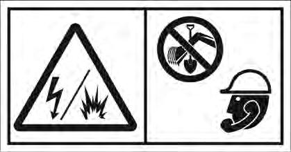
MACHINE SIGNS (DECALS)
Follow the instructions on all the Machine Signs (Decals) that are on the excavator. Replace any damaged machine signs and be sure they are in the correct locations. Machine signs are available from your Bobcat Excavator dealer.
MACHINE SIGNS (DECALS) (CONT’D)
Follow the instructions on all the Machine Signs (Decals) that are on the excavator. Replace any damaged machine signs and be sure they are in the correct locations. Machine signs are available from your Bobcat Excavator dealer.

Publications And Training Resources
The following publications are also available for your Bobcat Excavator. You can order them from your Bobcat dealer.
For the latest information on Bobcat products and the Bobcat Company, visit our web site at www.bobcat.com; you can also order Operator and Service Training materials online through www.bobcatstore.com
OPERATION & MAINTENANCE MANUAL
6986942
- Complete instructions on the correct operation and the routine maintenance of the BOBCAT Excavator.
SERVICE MANUAL
6986943
- Complete maintenance instructions for your BOBCAT Excavator.

SAFETY MANUAL
6901951
- Provide basic safety procedures and warnings for your BOBCAT Excavator
OPERATOR’S HANDBOOK
6903819
Gives basic operation instructions and safety warnings
COMPACT EXCAVATOR OPERATOR TRAINING COURSE
6903186
Introduces operator to step-by-step basics of Compact Excavator operation. Also available in Spanish P/N 6903228
EXCAVATOR SERVICE SAFETY COURSE
6900916
Introduces Service Technicians to step-by-step basics of proper and safe excavator maintenance and servicing procedures
OPERATOR SAFETY VIDEO
6903181
Provides basic safety instructions
OPERATOR SAFETY DVD
6904762
Provides basic safety instructions contained in all Bobcat Safety Videos in both English and Spanish.

Instruments And Consoles
Cab Interior Light (If Equipped)
REF. NO DESCRIPTION
FUNCTION / OPERATION
1 Left Joystick(See HYDRAULIC CONTROLS on Page OI-16.)
2 HornPress button to sound horn.
3 Fan Motor Switch (If Equipped)
4 Air Conditioning Switch (If Equipped)
5 Temperature Control (If Equipped)
6 Wiper / Washer Switch (If Equipped)
Turn clockwise to increase fan speed; counterclockwise to decrease.
Press top of switch to turn air conditioner ON (light in switch will be ON), Press bottom of switch to turn OFF.
Turn clockwise to increase temperature; counterclockwise to decrease.
Press the switch to the left to turn wiper ON. Press and hold switch to the left to activate window washer window washer. Press the switch to the right to turn wiper OFF.
7 Hydraulic XChange Switch (If Equipped)
8 Secondary Auxiliary Switch (If Equipped)
Press and hold the switch to the right to fully retract hydraulic pins. Press and hold the switch to the left to fully extend hydraulic pins.
Move the switch to the right and use the boom swing pedal to activate the secondary auxiliary hydraulics, Move the switch to the left for boom swing function.
9 Not Used- - -

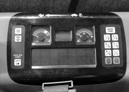
INSTRUMENTS AND CONSOLES (CONT’D)
Right Console
Figure OI-3
Right Console [Figure OI-3]
1 Right Joystick (See HYDRAULIC CONTROLS on Page OI-16.)
2 Auxiliary Hydraulic Switch Controls the fluid flow to the auxiliary quick couplers (attachment). (See Auxiliary Hydraulics on Page OI-19.)
3 Blade Control LeverControls raising and lowering the blade. Pushed all the way forward puts blade in float position. (See BLADE CONTROL LEVER on Page OI-20.)
4 Speed Control Lever Controls RPM of the engine

5 Two Speed ButtonEngages and disengages High Range Travel Speed, (See TwoSpeed Travel on Page OI-7.)
6 Key Switch (STANDARD Panel Only)
Always perform the PRESTARTING PROCEDURE, (See PRE-STARTING PROCEDURE on Page OI-23.) Before starting the engine. (See STARTING THE ENGINE on Page OI-25.)
7 Auxiliary Power Outlet
12 volt receptacle for accessories.
8 Auxiliary Hydraulic Button Activates and deactivates auxiliary hydraulic function. (See Auxiliary Hydraulics on Page OI-19.)
9 HOURS / JOB / RPM Press to show HOURS, JOB CLOCK or Engine RPM in LCD (Liquid Crystal Display, Item 11.) (See Password Lockout Feature on Page SA-5.)
10 LIGHTS / HOLD FOR CODES
Press once to turn lights ON; press again to turn lights OFF, Press and hold two seconds for display of SERVICE CODES in LCD (Item 11).
11 TEMPeratureShows the engine coolant temperature.
12 LCD (Liquid Crystal Display)
The LCD is the HOURMETER during normal operation of the excavator, When preheat is activated (Keyless Start), the LCD will show remaining preheat time. Can also be used to display JOB CLOCK or Engine RPM. (See Job Clock on Page SA-5.)
13 FUEL GaugeShows the amount of fuel in the tank.
14 Keyless (OPTIONAL)
(Always perform the PRESTARTING PROCEDURE, (See PRE-STARTING PROCEDURE on Page OI-23.) Before starting the engine. (See STARTING THE ENGINE on Page OI-25.)
15 Function Icons (See Function Icons on Page OI-5.)
16 JobOn when JOB CLOCK is activated.
17 RPMOn when Engine RPM is activated.
NOTE: Always turn key switch and all accessories to OFF position when the engine is stopped, the battery will discharge if the key is left ON. Audible alarm will sound if the key is in the ON position with the engine stopped.
INSTRUMENTS AND CONSOLES (CONT’D)

Function Icons
The table below shows the Icons, their function and other important information.
* This is the normal operating condition.
♦These functions are monitored and have SERVICE CODES associated with them, See SYSTEM SETUP & ANALYSIS Page SA-3 for descriptions of SERVICE CODES.
INSTRUMENTS AND CONTROLS (CONT’D)
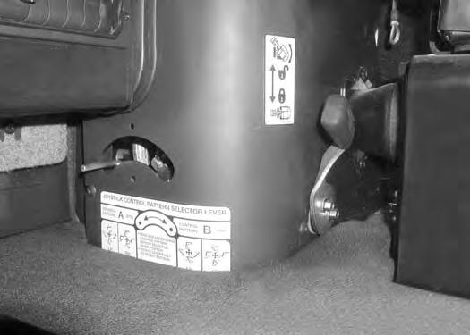
STD / ISO Selector Valve
Figure OI-5
Move the lever (Item 1) to the right (Item 2) to select STANDARD Control Pattern. Move to the left (Item 3) to select ISO Control Pattern [Figure OI-5]
Upperstructure Slew Lock
Figure OI-6
Push down on the front (Item 1) [Figure OI-6] of the foot pedal to engage the upperstructure slew lock.

Push down on the rear (Item 2) [Figure OI-6] to disengage the upperstructure slew lock.
NOTE:Upperstructure must be in the straight forward or straight rearward position for upperstructure to lock.
INSTRUMENTS AND CONTROLS (CONT’D)

Raising And Lowering The Console
Raise the console before exiting the cab.
Two-Speed Travel
Pull up on the release handle [Figure OI-7]. The lift spring will assist in raising the console.
Lower the console before operating the excavator.
Push down on the console [Figure OI-7] until the latch is engaged.


NOTE:When the console is raised, the hydraulic and traction system functions are locked and will not operate.
If the engine stops, the boom / bucket (attachments) can be lowered to the ground using hydraulic pressure in the accumulator.
The control console must be in the locked down position, and the key switch in the ON position.
Press the button (Item 1) [Figure OI-8] to engage the High Range. Press a second time to disengage.
When High Range is engaged, the two speed travel icon (Item 1) [Figure OI-9] will illuminate.
Press the button (Item 1) [Figure OI-8] again to disengage.
OPERATOR CANOPY (ROPS / TOPS)
Description
The excavator has an operator canopy (ROPS / TOPS) (Roll Over Protective Structure / Tip Over Protective Structure) as standard equipment. The ROPS / TOPS meets ISO 3471 and ISO 12117.
Both the cab and canopy provide operator protection if the excavator is tipped over. The seat belt must be worn for ROPS / TOPS protection.
Warning
Never modify operator cab by welding, grinding, drilling holes or adding attachments unless instructed to do so by Bobcat Company. Changes to the cab can cause loss of operator protection from rollover and falling objects, and result in injury or death.
W-2069-0200
OPERATOR CAB (ROPS / TOPS)
Description
The excavator has an optional operator cab (ROPS / TOPS) (Roll Over Protective Structure / Tip Over Protective Structure). The ROPS / TOPS meets ISO 3471 and ISO 12117.
An enclosed cab (ROPS / TOPS) is an Option or can be installed as a Field Accessory.
Both the cab and canopy provide operator protection if the excavator is tipped over. The seat belt must be worn for ROPS / TOPS protection.
Warning
Never modify operator cab by welding, grinding, drilling holes or adding attachments unless instructed to do so by Bobcat Company. Changes to the cab can cause loss of operator protection from rollover and falling objects, and result in injury or death.
W-2069-0200
OPERATOR CAB (ROPS / TOPS) (CONT’D)
Cab Door
The cab door can be locked (Item 1) [Figure OI-10] with the same key as the starter switch.
Push the door all the way open (Item 2) [Figure OI-10] until the latch engages to hold the door in the open position.
When the door is in the open position, push down on the latch (Item 1) [Figure OI-11] and close the door.

From inside the cab, open the door using handle (Item 2) [Figure OI-11]

OPERATOR CAB (ROPS / TOPS) (CONT’D)

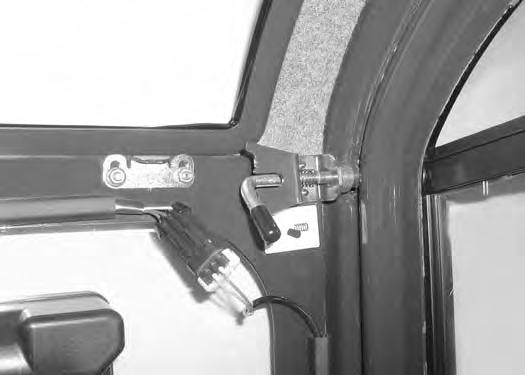
Front Window
Opening The Front Window
Figure OI-12
Use both window grab handles to pull the top of the window in [Figure OI-14].
Continue moving the window in and up over the operator’s head until the window is fully raised.
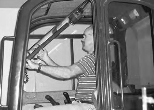
Retract the two top window latch pins (Item 1) [Figure OI-12].
Turn the two top latches (Item 1) [Figure OI-13] to the unlocked position.
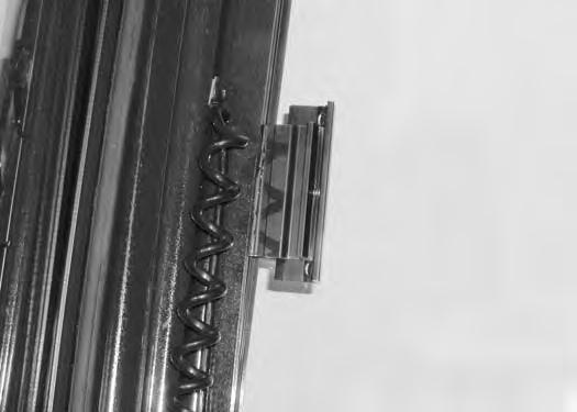
When the window is fully raised, the latch (Item 1) will close on the bracket. Turn the two top latches (Item 2) [Figure OI-15] to the locked position.
Closing The Front Window
Support the window while releasing both window latch pins and placing the pins in the unlocked position [Figure OI-15]

Support the window using the left grab handle and pull down on the latch (Item 1) [Figure OI-15] to release the window.
Use both window grab handles to pull the window down [Figure OI-14]
Rotate the top latches (Item 1) [Figure OI-13] to the locked position (Item 1) [Figure OI-12]
OPERATOR CAB (ROPS / TOPS) (CONT’D)


Front Wiper
Window Washer Reservoir
OPERATOR CAB (ROPS / TOPS) (CONT’D)
Right Side Windows

Opening the right rear window
Push
Opening the right front window


OPERATOR CAB (ROPS / TOPS) (CONT’D)

Heating, Ventilation, and Air Conditioning Duct
NOTE: The air conditioner duct can be ordered and used on heater models.
There are two HVAC ducts that the operator can choose to install.
Installation
Remove the screw and pull straight up to remove the duct (Item 1) [Figure OI-22]
NOTE: This duct can be removed for improved operator visibility.


Travel Controls
Forward And Reverse Travel
NOTE: The following procedures describe forward, reverse, left & right as seated in the operator’s seat.
Turning Right Turn
Figure OI-26
Right Turn (Forward)
Put the blade so that it is at the front of the machine (as you sit in the operator’s seat). Slowly move both steering levers* (Item 1) [Figure OI-25] forward for forward travel; backward for reverse travel.


* Travel can also be controlled with foot pedals (Item 2) [Figure OI-25]. Pivot the heel of the pedals forward for additional space on the floor.
Warning
AVOID INJURY OR DEATH
•Check the blade location before traveling. When the blade is to the rear, operate the steering levers/foot pedals in the opposite direction to when the blade is in the front.
•Move the steering levers/foot pedals slowly. Abrupt lever motion will cause the machine to jerk.

W-2235-0396
Push the left steering lever forward to turn right [Figure OI-26] while traveling forward.
Figure OI-27
Right Turn (Reverse)
Pull the left steering lever backward to turn right while traveling backward [Figure OI-27]
TRAVEL CONTROLS (CONT’D)
Turning (Cont’d)
Counter-Rotation Right Turn
Figure OI-28
Counter-Rotation (Right Turn)
Push the left steering lever forward and pull the right steering lever backward [Figure OI-28].

Left Turn
Left Turn (Forward)
B-19989
Push the right steering lever forward to turn left while traveling forward [Figure OI-29]


Left Turn (Reverse)
B-19990
Pull the right steering lever backward to turn left while traveling backward [Figure OI-30]
Counter-Rotation Left Turn
Counter-Rotation (Left Turn)
B-19991
Push the right steering lever forward and pull the left steering lever backward [Figure OI-31].
Hydraulic Controls
Description
The work equipment (boom, arm, bucket, and upperstructure slew) is operated by using the left and right control levers (joysticks). These joysticks can be used in either a STANDARD Control Pattern [Figure OI32] & [Figure OI-33] or in the ISO Control Pattern [Figure OI-34] & [Figure OI-35]
STANDARD Control Pattern
Left Control Lever (Joystick)
Figure OI-32
The left lever (joystick) is used to operate the arm and slew the upperstructure [Figure OI-32]

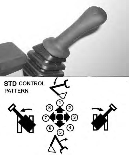
1.Boom lower.
2.Boom lower and slew right.
3.Slew right.
4.Boom raise and slew right.
5.Boom raise.
6.Boom raise and slew left.
7.Slew left.
8.Boom lower and slew left.
Important
Before slewing the upperstructure, make sure the slew lock is disengaged.
I-2051-0905
Right Control Lever (Joystick)
Figure OI-33
The right lever (joystick) is used to operate the boom and bucket [Figure OI-33]
1.Arm out.
2.Arm out and bucket dump.
3.Bucket dump.
4.Arm in and bucket dump.
5.Arm in.
6.Arm in and bucket curl.
7.Bucket curl.
8.Arm out and bucket curl.
Warning
AVOID INJURY OR DEATH
Before leaving the machine:
•Lower the work equipment to the ground.
•Lower the blade to the ground.
•Stop the engine & remove the key.
W-2196-0595
HYDRAULIC CONTROLS (CONT’D)
ISO Control Pattern
Left Control Lever (Joystick)
Figure OI-34
The left lever (joystick) is used to operate the arm and slew the upperstructure [Figure OI-34]


1.Arm out.
2.Arm out and slew right.
3.Slew right.
4.Arm in and slew right.
5.Arm in.
6.Arm in and slew left.
7.Slew left.
8.Arm out and slew left.
Important
Before slewing the upperstructure, make sure the slew lock is disengaged.
I-2051-0905
Right Control Lever (Joystick)
The right lever (joystick) is used to operate the boom and bucket [Figure OI-35]
1.Boom lower.
2.Boom lower and bucket dump.
3.Bucket dump.
4.Boom raise and bucket dump.
5.Boom raise.
6.Boom raise and bucket curl.
7.Bucket curl.
8.Boom lower and bucket curl.
Warning
AVOID INJURY OR DEATH
Before leaving the machine:
•Lower the work equipment to the ground.
•Lower the blade to the ground.
•Stop the engine & remove the key.
W-2196-0595
HYDRAULIC CONTROLS (CONT’D)
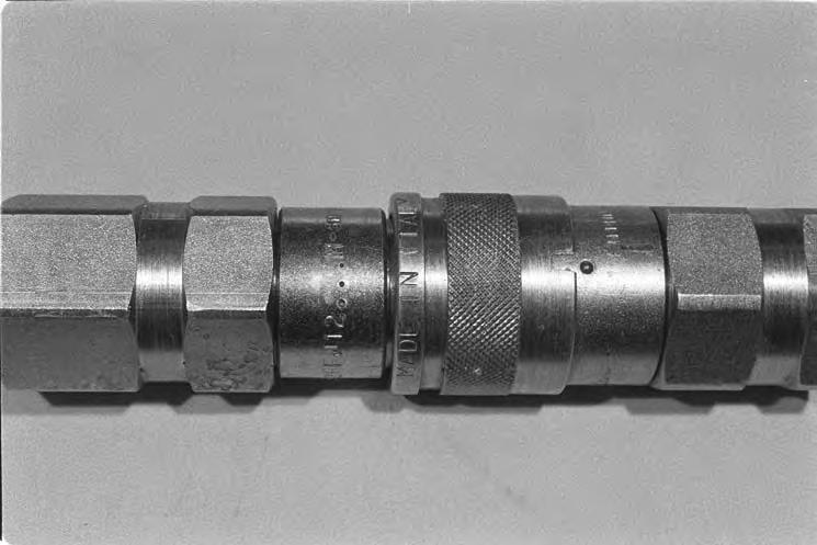
Quick Couplers
Warning
Avoid Burns
Hydraulic fluid, tubes, fittings and quick couplers can get hot when running machine and attachments. Be careful when connecting and disconnecting quick couplers.
To Disconnect:
Figure OI-37
Excavators and attachments are supplied with flush faced couplers (Item 1) [Figure OI-36]

To Connect:
Remove any dirt or debris from the surface of both the male and female couplers, and from the outside diameter of the male coupler. Visually check the couplers for corroding, cracking, damage, or excessive wear, if any of these conditions exist, the coupler(s) (Item 1) [Figure OI36] must be replaced.
Install the male coupler into the female coupler. Full connection is made when the ball release sleeve slides forward on the female coupler.
Hold the male coupler (Item 1). Retract the sleeve (Item 2) [Figure OI-37] on the female coupler until the couplers disconnect.
HYDRAULIC CONTROLS (CONT’D)
Auxiliary Hydraulics
Figure OI-38
Press the Auxiliary Hydraulics button on the right console (Item 1) [Figure OI-38]
Figure OI-39
Move the switch (Item 1) [Figure OI-39] on the right control lever to the right or left to direct fluid flow to an attachment such as a breaker or hydraulic clamp.
Press the switch (Item 2) [Figure OI-39] on the front of the handle to provide constant flow to the female coupler.
NOTE: Pressing the switch (Item 1) [Figure OI-39] to the left while pressing the switch on the front of the handle will provide constant flow to the male coupler.


Press the switch (Item 2) [Figure OI-39] a second time to stop auxiliary flow to the quick couplers.
Relieve Hydraulic Pressure (Excavator And Attachment)
Excavator:
Put the attachment flat on the ground.
Stop the engine and turn the key to ON (Standard) or press ENTER CODE Button (Keyless).
NOTE: The left console must be fully lowered for relieving hydraulic pressure.
Press AUX HYD Button (Item 1) [Figure OI-38] and then move the switch (Item 1) [Figure OI-39] to the right and left several times.

Attachments:
•Follow procedure above to release pressure in excavator.
•Connect male coupler from attachment to female coupler of excavator then repeat procedure above. This will release pressure in the attachment.
•Connect the female coupler from the attachment.
Hydraulic pressure in the auxiliary hydraulic system can make it difficult to engage quick couplers to an attachment.
Return To Tank Valve (If Equipped)
The return to tank valve is located under the right side cover.
Remove the spool lock (Item 1) [Figure OI-40] and push the spool in to direct auxiliary return hydraulic fluid to the reservoir.
Pull the spool out and install the spool lock (Item 1) [Figure OI-40] for two way hydraulic auxiliary flow operation.
Blade Control Lever


Raising And Lowering Blade
Figure OI-41
BOOM SWING PEDAL Operation
Figure OI-42
Pull the lever backward to raise the blade (Item 1) [Figure OI-41]
Push the lever forward to lower the blade (Item 2) [Figure OI-41].
Push the lever (Item 3) [Figure OI-41] forward until the lever is in the locked position to put the blade in the float position.
Pull the lever backward to unlock from the float position.
NOTE: Keep blade lowered for increased digging performance.
Release the pedal lock and pivot the heel of the pedal to the rear (Item 1) [Figure OI-42]
Push the toe of the pedal (Item 2) to swing the boom to the right; push the heel (Item 1) [Figure OI-42] to swing the boom to the left.
Figure OI-43
B-19937
NOTE: The purpose of the boom swing pedal is to offset the boom with respect to the upperstructure for digging close to a structure [Figure OI-43].

DAILY INSPECTION (CONT’D)
Daily Inspection And Maintenance
Maintenance work must be done at regular intervals. Failure to do so will result in excessive wear and early failures. The Service Schedule is a guide for correct maintenance of the Bobcat Excavator (See Daily Inspection And Maintenance on Page OI-22.) It is located inside the rear door of the excavator.
Check the following items before each day of operation:
•Operator Canopy or Cab (ROPS / TOPS) and mounting hardware.
•Seat belt and mounting hardware.
•Damaged decals, replace as needed.
•Check control console lockout.
•Air cleaner and intake hoses / clamps.
•Engine oil level and engine for leaks.
•Hydraulic fluid level and system for leaks.
•Grease all pivot points.
•Cylinder and attachment pivot points.
•Track tension.
•Repair broken and loose parts.
Warning
Operator must have instructions before operating the machine. Untrained operators can cause injury or death.
W-2001-0502
Fluids such as engine oil, hydraulic fluid, coolants, etc. must be disposed of in an environmentally safe manner. Some regulations require that certain spills and leaks on the ground must be cleaned in a specific manner. See local, state, and federal regulations for correct disposal.
Important
Pressure Washing Decals
•Never direct the stream at a low angle toward the decal that could damage the decal causing it to peel from the surface.
•Direct the stream at a 90 degree angle and at least 12 inches (300 mm) from the decal. Wash from the center of the decal toward the edges.
I-2226-0104
PRE-STARTING PROCEDURE
Operation & Maintenance Manual And Operator’s Handbook Locations

Read and understand the Operation & Maintenance Manual (Item 1) [Figure OI-44] (located inside the storage box on the back of the operator’s seat) and the Operator’s Handbook (Item 1) [Figure OI-45] or [Figure OI-46] before operating.


Entering The Excavator
Warning
AVOID INJURY OR DEATH
Instructions are necessary before operating or servicing machine. Read and understand the Operation & Maintenance Manual, Operator’s Handbook and signs (decals) on machine. Follow warnings and instructions in the manuals when making repairs, adjustments or servicing. Check for correct function after adjustments, repairs or service. Untrained operators and failure to follow instructions can cause injury or death.
PRE-STARTING PROCEDURE (CONT’D)
Seat Adjustment
Figure OI-48
Release the seat lever (Item 1) [Figure OI-48] to adjust the seat forward or backward.


Turn the handle (Item 2) to change the adjustment for operator weight. Turn the handle until the operator’s weight is shown in the window (Item 3) [Figure OI-48]
Release the lever (Item 4) [Figure OI-48] to change the incline of the seat back.
Sit in the seat and turn the knob (Item 5) [Figure OI-48] to adjust the height of the seat.
Seat Belt Adjustment
Figure OI-49
Fasten the seat belt [Figure OI-49]
Control Console
Figure OI-50
Lower the control console [Figure OI-50]
NOTE: There is a control lock switch in the left console which deactivates the hydraulic control levers (joysticks) and the traction drive system when the control console is raised. The console must be in the locked down position for the hydraulic control levers (joysticks) and traction system to operate.
NOTE:If the control lock switch does not deactivate the control levers and traction system when console is raised, see your Bobcat dealer for service.
STARTING THE ENGINE Key Switch
Warning
AVOID INJURY OR DEATH
•Fasten seat belt, start and operate only from the operator seat.
•Never wear loose clothing when working near machine.
W-2135-1188
Perform the PRE-STARTING PROCEDURE. (See PRESTARTING PROCEDURE on Page OI-23.)
Turn the key (Item 1) [Figure OI-53] to the ON position. If preheating is required, the glowplugs will automatically cycle and the remaining preheat time (in seconds) will show in the LCD. (Preheat icon will be ON).
Turn the key to START and release the key when the engine starts. It will return to the ON position [Figure OI53]


Stop the engine if the warning lights and alarm do not go OFF. Check for the cause before starting the engine again.
Turn the key switch OFF to stop the engine.
Put control levers (Item 1) [Figure OI-51] in the neutral position.

Warning
AVOID INJURY OR DEATH
When an engine is running in an enclosed area, fresh air must be added to avoid concentration of exhaust fumes. If the engine is stationary, vent the exhaust outside. Exhaust fumes contain odorless, invisible gases which can kill without warning.
W-2050-0807
Move the engine speed control (Item 1) [Figure OI-52] to low idle.
Important
Do not engage the starter for longer than 15 seconds at a time. Longer use can damage the starter by overheating. Allow starter to cool for one minute before using starter again.
I-2034-0700
Warning
AVOID INJURY OR DEATH
•Engines can have hot parts and hot exhaust gas. Keep flammable material away.
•Do not use machines in atmosphere containing explosive gas.
W-2051-1086
STARTING THE ENGINE (CONT’D) Keyless WARNING
AVOID INJURY OR DEATH
•Fasten seat belt, start and operate only from the operator seat.

•Never wear loose clothing when working near machine.
W-2135-1188
Perform the PRE-STARTING PROCEDURE. (See PRESTARTING PROCEDURE on Page OI-23.)
Press ENTER CODE Button (Item 1) [Figure OI-55]. The display will become lighted and there will be two short beeps, CodE will appear on the LCD.
Use the keypad (Item 2) [Figure OI-55] to enter the password. For each digit that you enter, a dash will appear on the LCD. (You have 40 seconds to enter the password or the process will abort and you will need to start over.) If the password was entered correctly, there will be one long beep.
NOTE:If the password was incorrect there will be three short beeps and “Error” will appear on the LCD. Press the ENTER CODE Button again and start over. After three failed attempts, you must wait three minutes to try again.
Press the START Button (Item 3) [Figure OI-55] and hold it until the engine starts.

Important
Do not engage the starter for longer than 15 seconds at a time. Longer use can damage the starter by overheating. Allow starter to cool for one minute before using starter again.
I-2034-0700
Press the STOP button (Item 4) [Figure OI-55] to stop the engine.
Stop the engine if the warning lights and alarm do not go OFF.
Check for the cause before starting the engine again.
Password Lockout Feature
See Password Lockout Feature. (See Password Lockout Feature on Page SA-5.)
STARTING THE ENGINE (CONT’D)
Cold Temperature Starting
Warning
AVOID INJURY OR DEATH
Do not use ether with glow plug (preheat) systems. Explosion can result which can cause injury, death, or severe engine damage.
W-2071-0907
If the temperature is below freezing, perform the following to make starting the engine easier:
•Replace the engine oil with the correct type and viscosity for the anticipated starting temperature. (See ENGINE LUBRICATION SYSTEM on Page PM18.)
•Make sure the battery is fully charged.
•Install an engine heater.
NOTE: If the battery is discharged (but not frozen) a booster battery can be used to jump start the excavator. (See Using A Booster Battery (Jump Starting) on Page PM-24.)
Key Switch
Push the speed control lever (Item 1) [Figure OI-56] fully forward.

Important
Do not engage the starter for longer than 15 seconds at a time. Longer use can damage the starter by overheating. Allow starter to cool for one minute before using starter again.
I-2034-0700
Turn the key to the ON position [Figure OI-57]
The preheat icon (Item 1) [Figure OI-58] will come ON. The glow plugs will automatically cycle. When the icon goes off, turn the key to start.

Release the key when the engine starts, it will return to the ON position.
Stop the engine if the warning lights and alarm do not go off. Check for the cause before starting the engine again.
When the engine speed increases, move the speed control lever to idle position until the engine warms.
STARTING THE ENGINE (CONT’D)
Cold Temperature Starting Procedure (Cont’d)
Keyless
Follow STARTING PROCEDURE See “Keyless” on PageOI-26.
If the preheat icon comes ON, wait for it to go off before pressing the START Button [Figure OI-58 on Page OI27].
The remaining preheat time (in seconds) will count down in the LCD.
Important
Do not engage the starter for longer than 15 seconds at a time. Longer use can damage the starter by overheating. Allow starter to cool for one minute before using starter again.
I-2034-0700
Important
Machines warmed up with moderate engine speed and light load have longer life.
I-2015-0284
Warning
AVOID INJURY OR DEATH
Do not use ether with glow plug (preheat) systems. Explosion can result which can cause injury, death, or severe engine damage.
W-2071-0907
Warming The Hydraulic System IMPORTANT
When the temperature is below -20°F (-30°C), hydrostatic oil must be warmed before starting. The hydrostatic system will not get enough oil at low temperatures and will be damaged. Park the machine in an area where the temperature will be above 0°F (-18°C) if possible.
I-2007-1285
Let the engine run at least 5 minutes to warm the engine and hydraulic fluid before operating the excavator.
Stopping The Engine And Leaving The Excavator
Procedure
Stop the machine on level ground. Lower the work equipment and the blade to the ground [Figure OI-60]

Move the speed control lever fully backward (Item 1) [Figure OI-61]

Run the engine at idle speed for about 5 minutes to allow it to cool.
Turn the key switch to STOP (Standard Panel) [Figure OI-62] or press the STOP Button (Deluxe Panel) (Item 1) [Figure OI-63]
Disconnect the seat belt. Remove the key from the switch to prevent operation of machine by unauthorized personnel. Raise the control console and exit the machine.

STOPPING THE ENGINE AND LEAVING THE EXCAVATOR (CONT’D)
Emergency Exit
The right side rear window and the front window provide exits.
Right Side Rear Window

Figure OI-64
Exit through the window [Figure OI-64]
Front Window
Figure OI-65
Open the front window and exit [Figure OI-65].
NOTE:If the excavator has a Special Applications Kit installed, the front window is NOT an emergency exit.
Attachments
Installing And Removing The Attachment (Hydraulic X-Change)
Installation
NOTE: Installation and removal of the bucket is shown. The procedure is the same for other attachments. Disconnect any hydraulic lines that are operated by hydraulic power before removing any attachments (breaker, auger, etc.).
Warning
AVOID INJURY OR DEATH
Never use attachments or buckets which are not approved by Bobcat Company. Buckets and attachments for safe loads of specified densities are approved for each model. Unapproved attachments can cause injury or death.
W-2052-0907
Warning
Both hydraulic pins must be fully extended through the attachment mounting holes and locked with both retainer pins and clips. Failure to fully engage and lock hydraulic pins can allow attachment to come off and cause serious injury or death.

W-2507-0706
Start the engine.
Swing the excavator arm fully to the left [Figure OI-66] (for better operator visibility when connecting attachments).


ATTACHMENTS (CONT’D)
Installing And Removing The Attachment (Hydraulic X-Change) (Cont’d)
Installation (Cont’d)
Figure OI-70
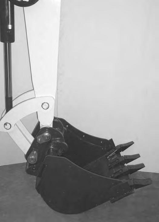
Raise the boom and extend (curl in) the bucket cylinder until the X-Change contacts the back of the attachment [Figure OI-70]
With the arm vertical, lower the boom until the hooks (Item 1) of the bucket disengage the X-Change pins (Item 2) and the plate (Item 3) [Figure OI-70] fully engages into the bucket crossmember.

Warning
Keep all bystanders 20 feet (6 m) away from equipment when operating. Contact with moving parts, a trench cave-in or flying objects can cause injury or death.
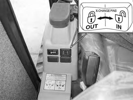
Press and hold the X-Change switch (Item 1) [Figure OI71] to the left and FULLY EXTEND the hydraulic pins.
Check that both hydraulic pins (Item 1) [Figure OI-72] are fully engaged to secure the attachment.
Warning
Both hydraulic pins must be fully extended through the attachment mounting holes and locked with both retainer pins and clips. Failure to fully engage and lock hydraulic pins can allow attachment to come off and cause serious injury or death.

ATTACHMENTS (CONT’D)
Installing And Removing The Attachment (Hydraulic X-Change) (Cont’d)


Installation (Cont’d)
Stop the engine.
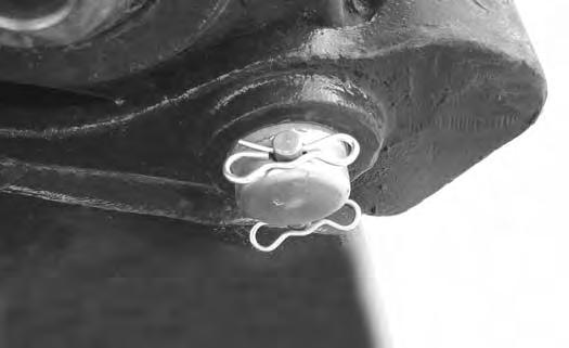
Install retainer pin (Item 1) and clips (Item 2) [Figure OI73] and [Figure OI-74] into each hydraulic pin (both sides).
Warning
Both hydraulic pins must be fully extended through the attachment mounting holes and locked with both retainer pins and clips. Failure to fully engage and lock hydraulic pins can allow attachment to come off and cause serious injury or death.
Removal
NOTE: Removal and installation of the bucket is shown. The procedure is the same for other attachments. Disconnect any hydraulic lines that are operated by hydraulic power before removing any attachments (breaker, auger, etc.).
Warning
Keep all bystanders 20 feet (6 m) away from equipment when operating. Contact with moving parts, a trench cave-in or flying objects can cause injury or death.
Park the excavator on a flat level surface. Put the attachment on the ground.
Stop the engine.
Remove retainer pin (Item 1) and retainer clips (Item 2) [Figure OI-73] and [Figure OI-75] from the hydraulic pin (both sides).
ATTACHMENTS (CONT’D)
Installing And Removing The Attachment (Hydraulic X-Change) (Cont’d)

Removal (Cont’d)
Install both retainer pins (Item 1) and clips (Item 2) [Figure OI-76] in the storage location.
Raise the boom and retract the bucket cylinder until the X-Change pins (Item 1) engage the attachment hooks (Item 2) [Figure OI-78] on the bucket.
Start the engine.
Press and hold the X-Change switch (Item 1) [Figure OI77] on the left console to the right to FULLY RETRACT the hydraulic pins.
Fully retract the bucket cylinder (bucket dump).
Lower the boom and arm until the attachment is on the ground and the X-Change pins are disengaged from the attachment hooks.
Move the arm toward the excavator until the X-Change pins are clear of the attachment [Figure OI-79]

ATTACHMENTS (CONT’D)
Installing And Removing The Attachment (Pin-On XChange)
Installation
NOTE: Installation and removal of the bucket is shown. The procedure is the same for other attachments. Disconnect any hydraulic lines that are operated by hydraulic power before removing any attachments (breaker, auger, etc.).
Warning
AVOID INJURY OR DEATH
Never use attachments or buckets which are not approved by Bobcat Company. Buckets and attachments for safe loads of specified densities are approved for each model. Unapproved attachments can cause injury or death.
W-2052-0907
Warning
Both hydraulic pins must be fully extended through the attachment mounting holes and locked with both retainer pins and clips. Failure to fully engage and lock hydraulic pins can allow attachment to come off and cause serious injury or death.


W-2507-0706
Figure OI-80
Inspect the pin (Item 1) [Figure OI-80] for wear or damage. Replace the pin as needed.
Apply a light coat of grease to the ends of the pin (Item 2) [Figure OI-80].
Figure OI-81
Start the engine and move the arm toward the bucket [Figure OI-81].
ATTACHMENTS (CONT’D)
Installing And Removing The Attachment (Pin-On XChange) (Cont’d)
Installation (Cont’d)
Figure OI-82
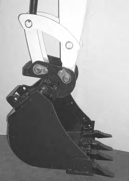
Raise the boom until the pins (Item 1) engage the hooks (Item 2) [Figure OI-82] on the bucket.
Raise the boom and extend the bucket cylinder until the X-Change contacts the attachment back [Figure OI-83]
With the arm vertical, lower the boom until the hooks (Item 1) of the bucket disengage the pins (Item 2) of the X-Change and the plate (Item 3) [Figure OI-83] fully engages in the bucket crossmember.
Warning
Keep all bystanders 20 feet (6 m) away from equipment when operating. Contact with moving parts, a trench cave-in or flying objects can cause injury or death.
ATTACHMENTS (CONT’D)
Installing And Removing The Attachment (Pin-On XChange) (Cont’d)
Installation (Cont’d)
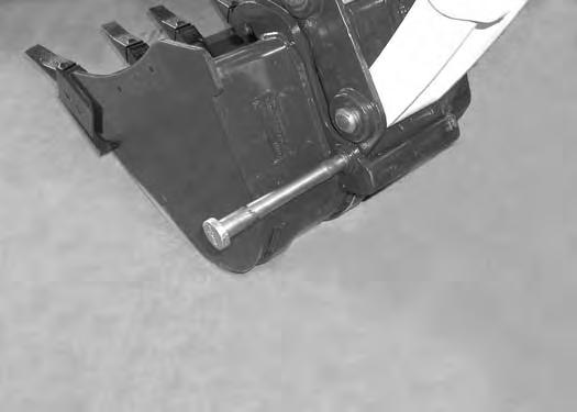
Stop the engine. Turn the start key to the ON position and move both hydraulic control levers to relieve hydraulic pressure.

Drive the pin (Item 1) [Figure OI-84] through the bucket mount and X-Change.
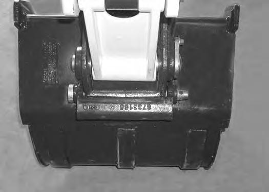
Install the retainer pin (Item 1) [Figure OI-85]
Check for proper installation.
Lift the attachment and fully extend and retract the bucket cylinder.
ATTACHMENTS (CONT’D)
Installing And Removing The Attachment (Pin-On XChange) (Cont’d)

Removal
Use the pin on X-Change when installing new attachments that are equipped with the pin on X-Change bracket.
NOTE: Removal and installation of the bucket is shown. The procedure is the same for other attachments. Disconnect any hydraulic lines that are operated by hydraulic power before removing any attachments (breaker, auger, etc.).
Warning
AVOID INJURY OR DEATH
Never use attachments or buckets which are not approved by Bobcat Company. Buckets and attachments for safe loads of specified densities are approved for each model. Unapproved attachments can cause injury or death.
Park the excavator on a flat level surface. Put the bucket on the ground [Figure OI-86]
With the engine off, turn the start key to the ON position and move both hydraulic control levers to relieve hydraulic pressure.
ATTACHMENTS (CONT’D)
Installing And Removing The Attachment (Pin-On XChange) (Cont’d)

Removal (Cont’d)
Warning
AVOID INJURY OR DEATH
Wear safety glasses to prevent eye injury when any of the following conditions exist:
•When fluids are under pressure.
•Flying debris or loose material is present.
•Engine is running.
•Tools are being used.
Start the engine, raise the boom approximately one foot and retract the bucket cylinder until the X-Change pins (Item 1) engage the hooks (Item 2) [Figure OI-89] on the bucket.
ATTACHMENTS (CONT’D)
Installing And Removing The Attachment (Pin-On XChange) (Cont’d)
ATTACHMENTS (CONT’D)
Installing And Removing The Attachment (Bolt-On XChange)
Installation
Use the bolt on X-Change components when installing older attachments that do not have the pin retention provision. (See you Bobcat dealer for required Bolt-On X-Change components.)


NOTE: Removal and installation of the bucket is shown. The procedure is the same for other attachments. Disconnect any hydraulic lines that are operated by hydraulic power before removing any attachments (breaker, auger, etc.).
Warning
AVOID INJURY OR DEATH
Never use attachments or buckets which are not approved by Bobcat Company. Buckets and attachments for safe loads of specified densities are approved for each model. Unapproved attachments can cause injury or death.

Fully retract the bucket cylinder and lower the arm to the ground [Figure OI-91]
With the engine off, turn the start key to the ON position and move both hydraulic control levers to relieve hydraulic pressure.
ATTACHMENTS (CONT’D)
Installing And Removing The Attachment (Bolt-On XChange) (Cont’d)

Installation (Cont’d)
Install the pin (Item 1) in the X-Change. Orientate the bolt holes (Item 2) [Figure OI-94] as shown.

Install the bolt (Item 1) [Figure OI-95] and washer through the X-Change and into the pin.
Start the engine and move the arm toward the bucket. Raise the boom until the pins (Item 1) engage the hooks (Item 2) [Figure OI-96] on the bucket.
ATTACHMENTS (CONT’D)
Installing And Removing The Attachment (Bolt-On XChange) (Cont’d)

Installation (Cont’d)
Raise the boom, and extend the bucket cylinder until the bucket is in the position shown [Figure OI-97]
With the arm vertical, lower the boom until the hooks (Item 1) of the bucket disengage the pins (Item 2) of the X-Change and plate (Item 3) [Figure OI-97] engages in the bucket crossmember.
Stop the engine. Turn the start key to the ON position and move both hydraulic control levers to relieve hydraulic pressure.
Warning
Keep all bystanders 20 feet (6 m) away from equipment when operating. Contact with moving parts, a trench cave-in or flying objects can cause injury or death.
ATTACHMENTS (CONT’D)
Installing And Removing The Attachment (Bolt-On XChange) (Cont’d)
Installation (Cont’d)
Figure OI-99
Install the bolts (Item 1) [Figure OI-99] through the plate and into the X-Change.
Tighten the bolts to 130 ft.-lb. (177 N•m) torque. Retorque the bolts after every eight hours of operation.

Check for proper installation.
Lift the attachment and fully extend and retract the bucket cylinder.
Warning
Keep all bystanders 20 feet (6 m) away from equipment when operating. Contact with moving parts, a trench cave-in or flying objects can cause injury or death.
W-2119-0788
ATTACHMENTS (CONT’D)
Installing And Removing The Attachment (Bolt-On XChange)
Removal
Park the Excavator on a flat, level surface. Put the bucket on the ground [Figure
With the engine off, turn the start key to the ON position and move both hydraulic control levers to relieve hydraulic pressure.
Start the engine, raise the boom approximately one foot and extend the bucket cylinder until the X-Change pins (Item 1) engage the hooks (Item 2) [Figure OI-102] on the bucket.
ATTACHMENTS (CONT’D)
Installing And Removing The Attachment (Bolt-On XChange) (Cont’d)
Removal (Cont’d)
Fully retract the bucket cylinder and lower the boom and arm until the bucket is on the ground, and the X-Change pins (Item 1) are disengaged from the hooks (Item 2) [Figure OI-103]
Move the arm toward the Excavator until the X-Change pins are clear of the bucket.
ATTACHMENTS (CONT’D)
Installing And Removing The Attachment (Pin-On Attachment)
Installation
Warning
AVOID INJURY OR DEATH
Stop the machine on a firm flat surface. When removing or installing attachments (such as a bucket), always have a second person in the operator’s seat, give clear signals and work carefully.
W-2140-0189
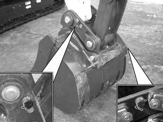
Figure OI-105
Install the arm into the bucket and align the mounting hole.
Install the pin (Item 1) [Figure OI-104] and washers.
Install the link (Item 2) in the bucket and align the mounting hole. Install the pin (Item 3) [Figure OI-104] and washers

Install the two retainer pins (Item 1) [Figure OI-105] Install grease in the grease fittings.
Removal
Park the excavator on a flat surface and lower the bucket fully.
Remove the two retainer pins (Item 1) [Figure OI-105]
Remove the washers and pins (Items 1 & 3) [Figure OI104].
Do not damage the dust seals in the arm.
Warning
AVOID INJURY OR DEATH
Never use attachments or buckets which are not approved by Bobcat Company. Buckets and attachments for safe loads of specified densities are approved for each model. Unapproved attachments can cause injury or death.
W-2052-0907
Operating Procedure
Inspect The Work Area
Before beginning operation, inspect the work area for unsafe conditions.
Look for sharp drop-offs or rough terrain. Have underground utility lines (gas, water, sewer, irrigation, etc.) located and marked.
Remove objects or other construction material that could damage the excavator or cause personal injury.
Lowering The Work Equipment (Engine STOPPED)
The hydraulic control levers control the movement of the boom, arm, bucket and upperstructure slew functions.
The console must be in the locked down position, and the key switch in the ON position.
Use the control lever to lower the boom.
Operating On Public Roads
When operating on a public road or highway, always follow local regulations. For example: A slow moving vehicle (SMV) sign, or direction signals may be required.
Check with utility companies for underground electrical, water, gas lines, etc. Work slowly in areas of underground utilities.
Run the engine at low idle speed to warm the engine and hydraulic system before operating the excavator.
Important
Machines warmed up with moderate engine speed and light load have longer life.
The joystick lock switch disengages the hydraulic control functions from the joysticks when the console are raised [Figure OI-106]
NOTE: If the engine stops, the boom / bucket (attachments) can be lowered to the ground using hydraulic pressure in the accumulator.
The control console(s) must be in the locked down position, and the key switch in the ON position.
Use the control lever to lower the boom.
Lower the control console(s) to engage the hydraulic control functions of the joysticks [Figure OI-106]

OPERATING PROCEDURE (CONT’D)
Lifting A Load
Do not exceed the Rated Lift Capacity. (See LIFT CHART on Page MST-4.)
Warning
AVOID INJURY OR DEATH
Do not exceed rated lift capacity. Excessive load can cause tipping or loss of control.
Extend the bucket cylinder completely and lower the boom to the ground. Stop the engine.
Wrap the chain assembly around the bucket mounting plate.
The optional lifting clamp attachment gives the excavator a wider range of use and mobility for debris removal [Figure OI-108]
The lifting clamp cylinder is operated by the auxiliary hydraulic system.
The lifting clamp cylinder must be fully retracted when the machine is being used for excavating.
The lift capacities are reduced by 270 lb. (122 Kg) if the excavator is equipped with the optional lifting clamp.
Warning
AVOID INJURY OR DEATH
Make sure the load is evenly weighted and centered on the lifting chain, and is secured to prevent the load from shifting [Figure OI-107]

Lift and position the load. Once the load is in position and tension is removed from the lift chain (secondary lift system), remove the secondary lift system.
Check area to be excavated for overhead or underground lines such as electrical, gas, oil, water, etc. CALL 1-888-258-0808 and consult local utilities before digging. Extreme caution must be used in areas where utility lines are present.
W-2116-0903
OPERATING PROCEDURE (CONT’D)
Excavating
Lower the blade to provide stability.
Figure OI-109
Extend the arm, lower the boom, and open the bucket [Figure OI-109].
Raise the boom, retract the arm and curl the bucket [Figure OI-111]
Rotate the upperstructure.
NOTE:Do not allow the bucket teeth to contact the ground when swinging the upperstructure.
Warning
Keep all bystanders 20 feet (6 m) away from equipment when operating. Contact with moving parts, a trench cave-in or flying objects can cause injury or death.
Retract the arm, while lowering boom and curling the bucket [Figure OI-110].
OPERATING PROCEDURE (CONT’D)
Excavating (Cont’d)
Extend
Important
Avoid operating hydraulics over relief pressure. Failure to do so will overheat hydraulic components. I-2220-0503
Do not dig under the excavator [Figure OI-113]
Do not use the bucket as a breaker or pile driver. It is better to excavate hard or rocky ground after breaking it with other equipment. This will reduce damage to the excavator.
Do not move the excavator while the bucket is in the ground.
Dig only by moving the boom and arm toward the excavator.
Do not back dig (digging by moving the boom and arm away from the excavator). Damage to the X-Change and attachments may occur.