4 minute read
Bearing cover 9 - Generator


Preparation - Remove starter motor - Detach gearbox/clutch cover assembly - Remove clutch - Remove flywheel
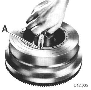
Rotor Removal - Extract spring clip A from flywheel magnet by inserting snip-nosed pliers into cut-outs provided
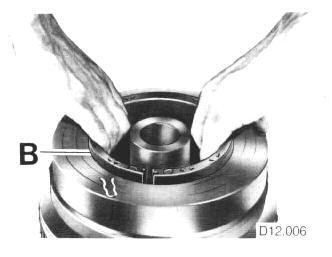
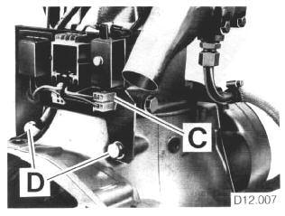
- Pull magnet B from flywheel with even movement, if necessary with suitable puller Generating Equipment Removal - Disconnect leads from temperature sensor and remove stator cable plug C from socket on equipment carrier - Remove bolts D (13 & 19 mm), noting position of spacers, washers and injector pipe clip (if fitted) and remove carrier and equipment complete from engine.

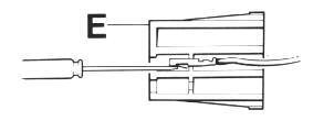
Stator Removal - Detach plug E from stator cables with fine implement, first marking their positions.
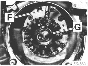
- Flatten lockwasher/cable clip F (renew on assembly), securing stator cable to bearing housing (SW 13) - Remove bolts G (7 mm) and lift off stator
Notes on Assembly - Grip magnet (rotor) firmly by hand and carefully place in flywheel, taking care to avoid jamming by lowering unevenly. If necessary, tap magnet with judicious use of soft-faced hammer
CAUTION
Do not hit magnet directly with a metal tool, or heat flywheel (loss of magnetism can result) - Lay stator harness close to bearing housing, to avoid contact with flywheel - Bend tags of stator cable end slightly to ensure firm fit before fitting to plug. Note fitted positions of cables.
Operation check and fault-finding
- Check that cable insulation is in order - Examine stator windings for possible damage - Check all connections for corrosion and ensure that connections are firm - The generator generates current without mechanical contacts and has no bearings.
Faults, therefore, generally arise from shortcircuits, loose or wrong connections in electrical circuit of boat.
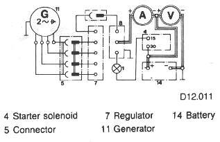
When faults occur, first check circuit, then operation of generator in situ (see wiring diagram)
Required for testing are:
Voltmeters 0-15 DC, 0-250 AC
Ammeter 0-40
Test/amp 12V
Fault Possible Cause Check Remedy
Control lamp remains lit after starting engine Faulty impulse transmitter. Faukts in boat circuit (e.g. short circuits)
No charge Check impulse transmitter (see section checking procedure 1)
Check charge (see checking procedure 2) Check boat circuit for faults. Renew impulse transmitter
See 2 (this table)
No charge Defective control unit Check voltage (see checking procedure 3)
Faulty generator (control unit is usually also defective) Check voltage (see checking procedure 3) Depending on result renew control unit and/or generator
Renew generator rotor and/or stator. Possibly renew control unit.
Checking Procedure 1 – Impulse Transmitter
Thin red lead of impulse transmitter earths control lamp when engine is stationery. When charge from control unit passes through transmitter, this earth is interrupted.
To check: - Disconnect thin red lead from boat circuit and connect 12V testlamp connected to B+ (charge lead) - With the engine stationary, testlamp should light, and at 1150 rpm extinguish - If the lamp does not extinguish, impulse transmitter is defective and should be renewed, or generator is not charging.
Checking Procedure 2 – Charge Current Charge current passes from control unit (white lead) through implulse transmitter (black lead – thick red lead) to B+ (connection 30)
To check: - With engine stationary, disconnect thick red cable from boat circuit and interpose 0-40 Amp ammeter - Start engine, switch one or two items of electrical equipment on (to load battery) - When no or insufficient charge are shown, control unit and/or generator are defective - For further fault location, voltage between each of the 2 black leads, red lead and generator should be checked.
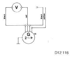
Checking Procedure 3 – Voltage Check (without load)
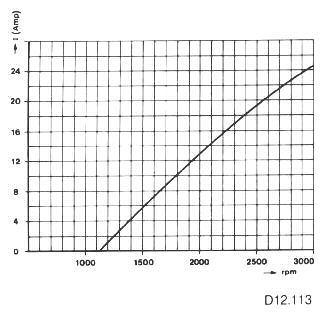
This check enables generator to be checked independently of control unit and battery - With the engine stationery, disconnect control unit from generator (2 black, red lead from 4 pole plug) - Connect one black lead and red lead to 250V voltmeter, ensuring remaining black lead cannot earth - Start engine, set to maximum speed and compare reading with that specified (see diagram) - Repeat test with second lead - If reading is correct, generator is in order and charging fault lies with control unit or boat circuit.
- If reading is not adequate, whereby reading of leads 1 and 2 are different, there are 2 possibilities: - when both leads lie below the correct reading, rotor magnetism is inadequate and rotor should be replaced - when only one lead shows a low reading, a fault in the stator windings is indicated and the stator should be renewed.