12 minute read
Electrical Installation


Beta Marine has 6 control panels: A, AB, ABV, ABVW B or C. The Beta 10 to Beta 25 use the A, ABV, ABVW, B and C control panels. The engine harness is common to all. 1. These control panels must not be installed where sea water spray can get at them. A suitable flap or cover must be fitted.
2. Control Panels must be fitted in a location where the helmsman can either see or hear the alarm system. 3. For standard wiring diagrams, see back of manual. 4. Our standard wiring harness has a 3 metre loom.
As an optional extra, Beta can provide various lengths of extension looms for runs of over 3m, but this kit includes a start relay to overcome the voltage drop. (See drawing 300-58520). Care must be taken when pushing the two halves of the plug together to ensure that individual pins do not fall out. To prevent corrosion and assist in assembly we recommend that the plug is packed with petroleum jelly (Vaseline) and then carefully pushed together. The plastic boots should cover both halves and overlap.
A cable tie is then put around to hold the two halves in position and help prevent any ingress of water. 5. All cables must be adequately clipped and protected from abrasion.
6. Electrical systems shall be designed and installed so as to ensure proper operation of the craft under normal conditions of use and shall be such as to minimise risk of fire and electric shock.
7. Attention shall be paid to the provision of overload and short circuit protection of all circuits; except engine starting circuits, supplied from batteries. 8. Ventilation shall be provided to prevent the accumulation of gases, which might be emitted from batteries. Batteries shall be firmly secured and protected from ingress of water.
9. All electrical equipment must be protected from sea water.
Sea water or rust in the starter will invalidate the warranty.
Typical Starter Motor Ratings
Starters used in Kobuta engines have the following standard capacities:
Engine Starter Capacity (kW)
Less than 700cc 0.8 - 1.0 700 to 1,500cc 1.0 - 1.4 1,500 to 3,000cc 1.4 - 2.0 Over 3,000cc 2.0 - 2.5
Suggested Minimum Engine Starter Battery Size
Engine Typical Battery Typical C.C.A Capacity (AH) Cold Cranking at a 20hr Rate Amperage
Beta 10, Beta 14, 35 - 50 AH 350 - 400 Beta 16, Beta 20 Beta 25, Beta 28, Beta 35, Beta 38, 65 - 75 AH 450 - 540 Beta 43 Beta 50, Beta 60 100 - 120 AH 580 - 670 Beta 75, Beta 90 150 - 180 AH 1050 - 1200
Keyswitch Terminations
The standard panel keyswitch can be used to tap off a switched positive ignition feed to power additional gauges. In this way these gauges will only be live whilst the engine is running, the engine is starting or the heaters are being used. For silver keyswitches, the terminal to achieve this ignition switched positive is marked ‘AC’. For black keyswitches, the terminal to achieve this ignition switched positive is marked ‘15/54’. For panels without any keyswitch, gauges can be driven from the 1 mm2 brown wire which terminates at 11 way connector terminal 4. This is a lower power switched positive, any additional power required from this connection must be feed through a relay, as noted below. Note: these keyswitch terminals are rated at 10 amps maximum, since they are already utilised for panel and alternator feeds Beta Marine recommend any additional requirements from these terminals must be fed through a relay. This relay should then be connected to it’s own fused positive supply directly from the engine battery. Beta drawing 202-06421 illustrating the wiring of a typical electric fuel lift pump with ignition switched relay is included in this manual.
Guidelines for Operation of Engine
Important Checks Prior to Initial Use
1. Generally, a new engine has the oil and anti-freeze removed after the works test. Fill the engine with the correct oil and antifreeze (see sections on Engine oil and
Cooling). Check gearbox oil level - see gearbox ‘Owners
Hand Book’.
2. Ensure the engine is free to turn without obstructions. 3. Ensure battery is fully charged and connected with the battery isolator in the ‘ON’ position. 4. Ensure "Morse" speed and gearbox cables are fitted correctly and that cable travel lengths are correct. Gear selection lever - all mechanical gearboxes: care must be taken to ensure that the remote control cable is adjusted so that the selector lever on the gearbox moves full travel and is brought "hard up" against its end stop in both directions. Failure to achieve the correct adjustment will reduce efficiency of the clutch and may cause slippage at low revs. Warranty will not be accepted on gearboxes returned in the warranty period for failure due to incorrect adjustment. 5. Open the sea water cock - carefully checking there are no water leaks.
6. Bleeding the fuel system for initial start up. a) The fuel system must have all the trapped air carefully ‘bled’ out; starting at the fuel tank and progressively working through to: the fuel/water trap, the fuel filter, to the fuel injection pump. b) Open the fuel tank stop tap/valve and then bleed the fuel/water separator of air as shown in manufacturer’s literature.
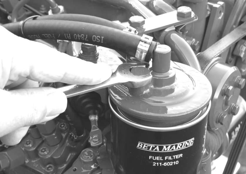
c) Fuel should now arrive at the fuel lift pump. d) Open the fuel bleed screw on top of the fuel filter by 1 to 2 turns, (see photo 18).
17 18

Fuel bleed screw
e) Move the hand priming lever on fuel lift pump up and down (see photo 17) until fuel with “no bubbles” comes out of the fuel filter bleed screw (see photo 18). The hand priming lever normally has about 90° travel; but the camshaft lobe may block this travel
requiring you to rotate the engine to obtain full travel.
f) Shut/tighten the bleed screw. g) Open the bleed screw on the fuel injection pump and again ‘bleed’ through to the injection pump. Continue to hand prime for 30 seconds to push fuel and any remaining air through the fuel pump. Clean all areas thoroughly of fuel with tissue paper. 7. Ensure engine is out of gear and set to 1/3 throttle - see "single lever control" instructions/manual. 8. Start engine (see normal starting). Note the engine may have to be turned over with the starter for a few seconds before it fires. Do not run the starter for more than 20 seconds. If the engine has not started after 20 seconds there is probably still air in the fuel system; disengage the starter and continue to hand prime the engine with the fuel lift pump lever for a further 30 seconds, then repeat. If engine does not start after 3 attempts then allow 5 minutes for the starter to cool down before repeating 6 (c) to 8. Note: The starter motor windings
can be burnt out with continuous cranking.
Caution. To avoid personal injury:
• Do not try to start the engine until you know how to stop the engine. • Do not bleed a hot engine as this could cause fuel to spill onto a hot exhaust manifold creating a danger of fire. • Do not mix petrol/gasoline or alcohol with diesel fuel.
This mixture can cause an explosion. • Do not get diesel fuel or oil on the flexible mounts - they will deteriorate rapidly if soaked in these. • All fuel must be removed from skin to prevent infection.
Beta Control Panels - A, AB, ABV, B and C Deluxe - with keyswitch.
Beta Control Panel ABVW - Keyless (without keyswitch)

To operate the engine: with the engine out of gear, set speed control lever to 1/3 throttle. 1) Turn key anti-clockwise to ‘HEAT’ position and hold for ten seconds. 2) Turn key clockwise to ‘RUN’ position. At this stage the instrument panel should illuminate:
19
• Green lamp for panel ‘power on’ should illuminate. • Buzzer should sound. • Red lamp for ‘low oil pressure’ should illuminate. • Red lamp for ‘high engine temperature’ should not illuminate (when engine is cold / cool / warm). This lamp will only ever illuminate if the engine is over temperature. • Red lamp for ‘no starter battery charge’ should illuminate. • Red lamp for ‘no domestic battery charge’. Only fitted with
panels AB and C and will illuminate only if 2nd ‘domestic’ alternator is fitted.
3)Turn to ‘START’ position and engine will motor, hold in position until engine fires (see initial start-up section for maximum time starter can be used). 4) Release key (when engine has started) to ‘RUN’ position.
• All red warning lamps should extinguish and buzzer should stop sounding. The oil pressure lamp may take a few seconds to switch off and the charge fail lamp may remain on until engine rpm is increased to approximately 1,000rpm if the engine was started on tickover. • Green lamp for ‘panel power on’ should still function. • If the ‘charge fail’ lamp remains on then “blip” the engine speed up to 2000 rev/min and it will go out (split charge relay drain).
This panel controls the engine with three water resistant push buttons instead of a keyswitch, and is less prone to damage and corrosion from sea water spray. To operate the engine: with the engine out of gear, set speed control lever to 1/3 throttle. 1)Press and hold ‘HEAT’ button for ten seconds maximum.
20
• Green lamp for panel ‘power on’ should illuminate. • Buzzer should sound. • Red lamp for ‘no starter battery charge’ should illuminate. • Red lamp for ‘high engine temperature’ should not illuminate (when engine is cold / cool / warm). This lamp will only ever illuminate if the engine is over temperature. • Red lamp for ‘low oil pressure’ should illuminate. 2) Press ‘START’ button and hold in position until engine fires (see initial start-up section for maximum time starter can be operated). Release button (when engine has started)

• All red warning lamps should extinguish and buzzer should stop sounding. The oil pressure lamp may take a few seconds to switch off and the charge fail lamp may remain on until engine rpm is increased to approximately 1,000rpm if the engine was started on tickover. • Green lamp for ‘panel power on’ should still function. 3) To stop the engine press the ‘STOP’ push button, hold in until engine stops. This button also switches the power off to the gauges, engine and ‘power on’ lamp. 4) To re-start the engine, simply repeat steps from ‘1’ above, there is no need to switch battery isolators off whilst remaining on board. 5) If leaving the boat, isolate start battery from engine and panel, to prevent accidental start up of engine and stop power leakage.
Every propulsion engine is fitted with a stop solenoid. To stop the engine simply press stop push button, hold in until engine stops, then turn key from ‘RUN’ to ‘OFF’ position. Do not turn the key to the off position when the engine is running, this will not allow the alternator to charge the battery.
Warning! Do not leave the key in ‘HEAT’ position for more than 15 seconds - this will damage the heater plugs and eventually lead to poor starting. When leaving the boat for an extended period:
• Turn off sea-cock (heat exchanger cooled engines). • Turn off battery isolator.
Notes for all panel types: Do not depress the stop button for more than ten seconds as this will lead to overheating
and failure of the solenoid. These engines are equipped with a mechanical stop lever in the event of electrical system failure. This lever is located on the starboard side of the engine above the speed control lever. See illustration below. Move the stop lever aft to stop the engine then return it to the run position.
21
Stop lever
Speed lever

Maintenance Schedule
Daily or every 8 hours running
• Check engine oil level. • Check gearbox oil level. • Check coolant level.
• Check battery fluid. • Check drive belt tension
• Ensure raw water inlet strainer is clear.
• Check stern gland lubrication (if used). • Drain off any water in fuel/water separator.
After the first 25 hours running
• Change gearbox lubricant (See separate gearbox manual). • Check that all external nuts, bolts and fastenings are tight.
See table for torque values. Do NOT over tighten. Special attention should be paid to the flexible mount lock nuts, these should be checked for tightness, starting with lower nut first in each case. If the lower nuts are found to be very loose, then the alignment of the shaft to the gearbox half coupling should be re-checked. Poor alignment due to loose flexible mount nuts will cause excessive vibration and knocking. • Check the belt tension on any second alternators fitted and adjust, see page 11. • Check ball joint nyloc nuts for tightness on both gearbox and speed control levers. Grease both fittings all over.
After first 50 hours
• Change engine lubricating oil. • Change oil filter. • Check for leaks on header tank tubestack. Tighten end cap bolt if required. • Drain off any water in fuel/water separator.
Every 150 hours
• If shallow sump (option) is fitted, change engine lubricating oil and filter.
Every year or 250 hours if sooner
• Change engine lubricating oil (standard sump) • Change lubricating oil filter • Check air cleaner element
• Check sea water pump impeller and change if worn. • Check wasting anode condition, replace when necessary.
In some environments this may be six monthly or less. • Remove heat exchanger tube stack, by undoing the bolt each end of the tube stack. Remove end cover, pull out tube stack and clean. Replace rubber ‘O’ rings and reassemble. Top up with antifreeze. Immediately engine is started check for leaks.
• Spray the key switch with WD40 or equivalent to lubricate the barrel.
• Check that all external nuts, bolts and fastenings are tight.
See table for torque values. • Check ball joint nyloc nuts for tightness on both gearbox and speed control levers.
Every 750 hours (In addition to 250 hours maintenance)
• Change air cleaner element. • Change fuel filter. • Change antifreeze. • Change gearbox oil. • Check electrical equipment, condition of hoses and belts, replace as necessary.