8 minute read
Disassembly Procedure

from Acer Aspire 9420 9410 7110 TravelMate 5620 5610 5110 Laptop Service Guide Manual - PDF DOWNLOAD

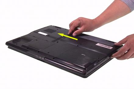
Removing the Battery Pack
1.Unlock the battery pack. 2.Slide the battery latch, hold it then remove the battery.

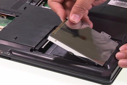
Removing the HDD Module
1.Release the three screws fastening the HDD module cover. 2.Detach the HDD module cover. 3.Release the two screws holding the HDD module then pull the HDD module as arrow indicates and remove the
HDD module.


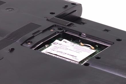
1.Release the two screws securing the miniPCI cover. 2.Remove the miniPCI cover. 3.Disconnect the wireless antenna then remove the wireless LAN card.
4.Release the two screws securing the RAM cover and remove the RAM cover. 5.Press the left and right latches to pop up the memory.


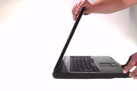
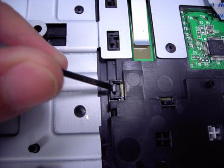
Removing the Keyboard
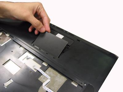
1.Open the notebook as shown. 2.Remove the middle cover. 3.There are four latches securing the keyboard. 4.Push those latches by the screw driver as shown and the keyboard will pop up a little.
5.Remove the keyboard and reverse it. 6.Carefully pull the keyboard FFC lock, then disconnect the keyboard FFC.


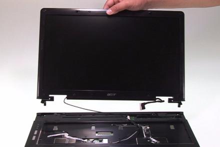
1.Pull carefully and disconnect the LCD cable. 2.Tear off the tape securing the wireless antenna and pull out the wireless antenna. 3.Release the two screws securing the LCD hinges on the bottom side. 4.Release the two screws fastening the LCD hinges on the rear side. 5.Release the two screws holding the LCD hinges as shown. 6.Then separate the LCD module from the main unit.


Separating the Upper Case and the Lower Case
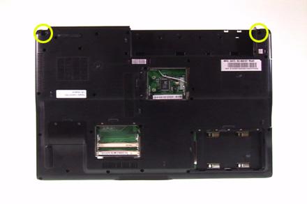
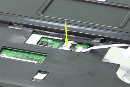
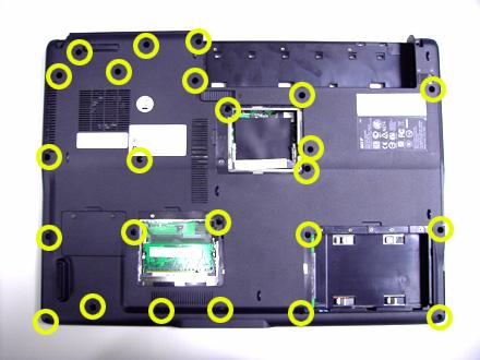
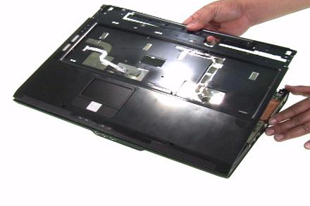
1.Release the connector lock and disconnect the touch pad FFC. 2.Release the connector lock and disconnect the function keyboard FFC. 3.Release the three screws securing the upper case. 4.Release the 27 screws holding the lower case. 5.Lift the upper case carefully and disconnect the lid switch cable. 6.Then separate the upper and the lower case.


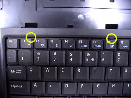
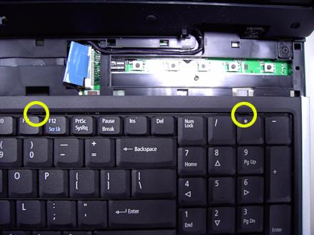
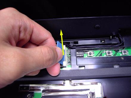
Removing the Function Keyboard
1.Release the FFC lock and disconnect the function keyboard FFC. 2.Release the four screws holding the function keyboard bracket. 3.Then remove the function keyboard bracket. 4.Carefully disconnect the microphone cable and remove the function keyboard.


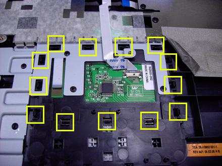
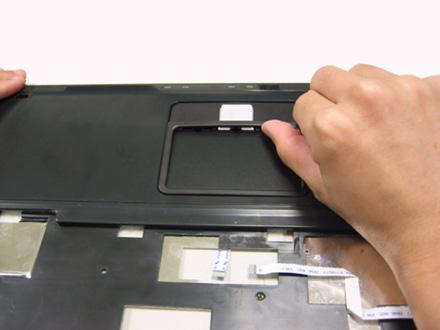
1.Carefully release the FFC lock and disconnect the touch pad board FFC. 2.There are 13 latches holding the touch pad bracket. 3.Unlock those latches with a screw driver as shown then detach the touch pad bracket. 4.Detach the touch pad board.

1.Slightly pull the ODD module and remove it. 2.Pull the dummy card from the slot and remove it.


Removing the Main Board
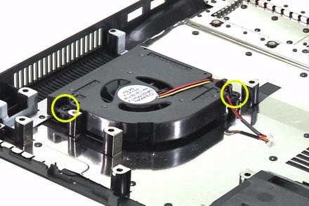
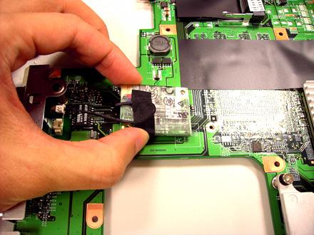
1.Disconnect the fan cable. 2.Disconnect the speaker cable and Bluetooth module cable. 3.Remove the four screws securing the main board. 4.Then detach the main board from the lower case.


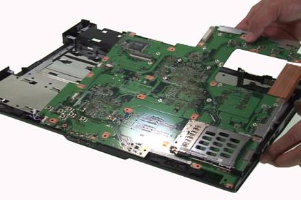
1.Release the two screws holding the heatsink. 2.Remove the heatsink.
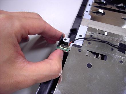
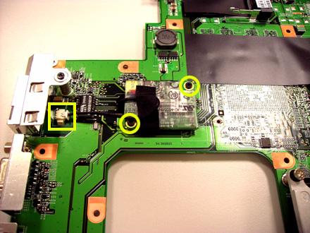
Removing the Bluetooth Module
1.Detach the bluetooth module from the lower case. 2.Carefully disconnect the bluetooth module cable.


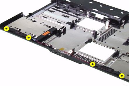
Removing the Speakers
1.Release the four screws securing the left and right speakers. 2.Remove the speakers from the lower case.

1.Carefully disconnect the MDC cable. 2.Release the two screws securing the MDC board then detach the MDC board. 3.Disconnect the MDC board cable.

Remove the Heatsink Module
1.Release the five screws securing the heatsink. 2.Remove the heatsink module.

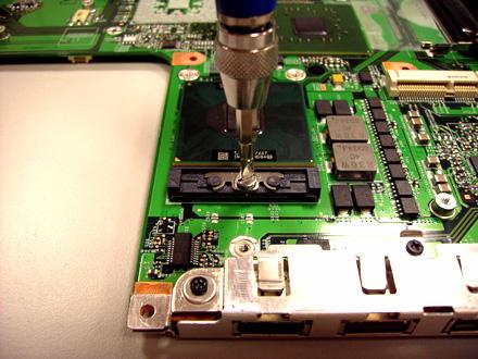
1.Release the screw counter clockwise with a flat screw driver. 2.Detach the CPU from the CPU socket.

LCD Disassembly
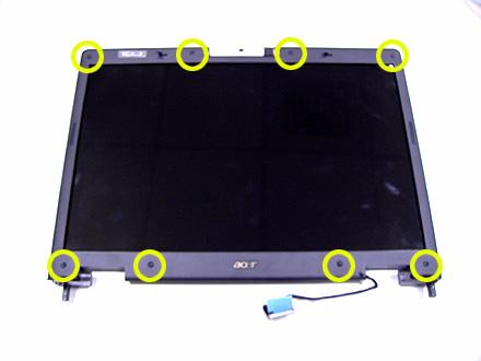
1.Remove the eight rubber caps on the LCD bezel and release the eight screws securing the LCD bezel. 2.Detach the LCD bezel from the LCD module as shown. 3.Release the screw holding the inverter board. 4.Disconnect the inverter board cables as shown and remove the inverter board.


5.Release the four screws securing the LCD panel. 6.Detach the LCD panel carefully and reverse it as shown. 7.Tear off the tapes holding the LCD panel cable carefully then disconnect the LCD panel. 8.Remove the antenna from the LCD cover.


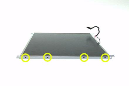
9.Release the four screws securing the left LCD bracket then remove the left LCD bracket. 10.Repeat the anterior step to remove the right LCD bracket.

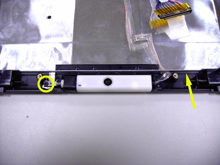
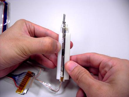
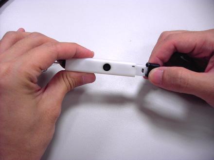
11.Release the screw holding the CCD module and carefully pull the CCD module cable and LCD cable through the latch bar and LCD cover. 12.Remove the CCD module cap. 13.Remove the CCD module ring. 14.Push the CCD module upper case a little bit. 15.Then Separate the lower case from the upper case. 16.Release the two screws holding the CCD module board the detach the CCD module board.


Troubleshooting
Please use the following procedures as a guide for computer problems.
Note: The diagnostic tests are intended to test only Acer products. Non-Acer products, prototype cards, or modified options may occur errors or invalid responses. 1.Obtain the detailed fail symptoms as many as possible. 2.Verify the symptoms by attempting to recreate, running the diagnostic tests or repeating the same operation. 3.Disassemble and assemble the unit without any power sources. 4.If any problem occurs, you can perform visual inspection before you fellow this chapter’s instructions. You can check the following: • Power cords are properly connected and secured; • There are no obvious shorts or opens; • There are no obviously burned or heated components; • All components appear normal.