6 minute read
Chapter 2 System Utilities


System Utilities
BIOS Setup Utility
The BIOS Setup Utility is a hardware configuration program built into your computer’s BIOS (Basic Input/ Output System). Your computer is already properly configured and optimized, and you do not need to run this utility. However, if you encounter configuration problems, you may need to run Setup. Please also refer to Chapter 4 Troubleshooting when problem arises. To activate the BIOS Utility, press m during POST (when “Press <F2> to enter Setup” message is prompted on the bottom of screen).
Navigating the BIOS Utility
There are five menu options: Main, Advanced, Security, Boot and Exit. Follow these instructions: To choose a menu, use the cursor left/right keys (zx). To choose a parameter, use the cursor up/down keys ( wy). To change the value of a parameter, press p or q. Press ^ while you are in any of the menu options to go to the Exit menu. In any menu, you can load default settings by pressing t. You can also press u to save any changes made and exit the BIOS Setup Utility.
NOTE: You can change the value of a parameter if it is enclosed in square brackets. Navigation keys for a particular menu are shown on the bottom of the screen. Help for parameters are found in the Item Specific Help part of the screen. Read this carefully when making changes to parameter values.
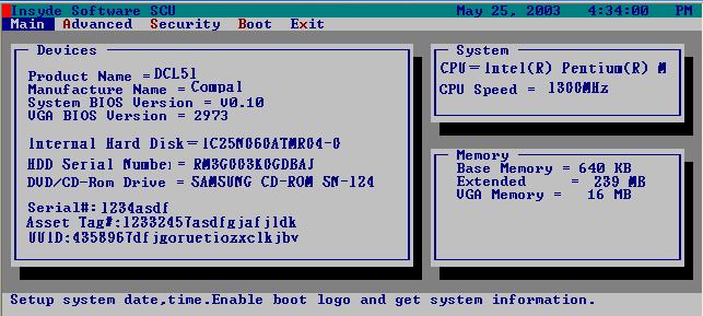
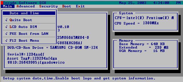
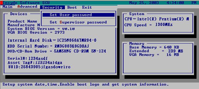
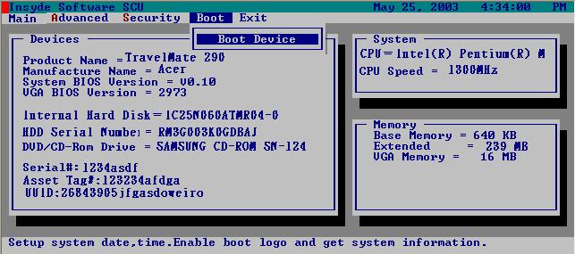
This menu provides you the information of the system.
Parameter Description
System BIOS Version Displays system BIOS version VGA BIOS Version Displays VGA BIOS version Serial # Displays the serial number of the unit. UUID Number UUID=16bytes. This will be visible only when there is an internal LAN device present. System Memory This field reports the memory size of system base memory. The size is fixed to 640KB. Extended Memory This field reports the memory size of the extended memory in the system. Extended Memory size=Total memory size CPU Speed CPU Speed= Max speed System Time and System Date Sets the system time and date. Quiet Boot Mode Control whether Customer Logo and Summary Screen are displayed or not. LCD Auto DIM Enabled: LCD brightness will automatically lower to save more power when AC is not present. Disabled: LCD brightness will NOT automatically lower to save more power when AC is not present. PXE Boot from LAN Enables “PXE Boot from LAN” function at DOS. F12 Boot Menu This field decides whether the OEM POST screen will have the following message: “Press <F12> Change Boot Device” or not during user’s quiet boot.
The Advanced screen contains parameters involving your hardware devices. It also provides advanced settings of the system.
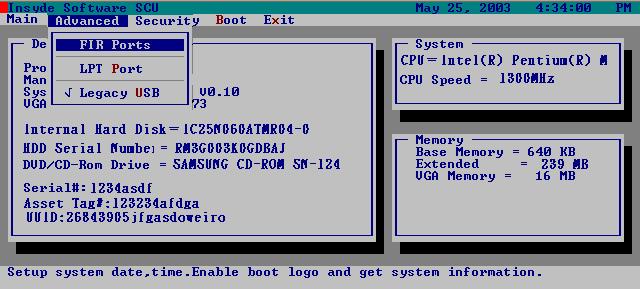
FIR Ports
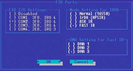
Description FIR I/O Settings Sets the base I/O address and IRQ for Infrared port. Option COM1, 3F8, IRQ4/ COM2, 2F8, IRQ3/ COM3, 3E8, IRQ4/ COM4, 2E8, IRQ3
Description DMA Setting for Fast IR Sets a DMA channel for the printer to operate in ECP mode. This parameter is enabled only if Mode is set to ECP. Option DMA1, DMA2, DMA3,
Mode Setting Normak (16550), IrDA (HPSIR), ASK IR, FAST IR
LPT Port
Legacy USB Support
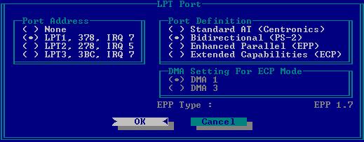
Description Port Definition Sets the mode for the parallel port. Standard AT: Normal mode (AT compatible) Bi-directional: Bi-directional mod (PS/2 compatible) Enhanced Parallel (EPP): EPP mode Extended Compabilities (ECP): ECP mode (requires DMA channel) Standard AT (Centronics),
Port Address Sets the base I/O address for the parallel port. When Mode is selected as EPP mode, “3BC” will not be available. Mode Setting If ECP mode has been selected, then DMA default is DMA1. Option
Bidirectional (PS-2),
Enhanced Parallel (EPP), Extended Capabilities
None/ LPT1, 378, IRQ7/ LPT2,
278, IRQ5/ LPT3, 3BC, IRQ7
DMA1, DAM3
Security
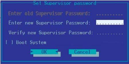
Set Supervisor/User Password
If password on boot is required, the password must be set otherwise it cannot be enabled.
The formats of the password are as follows:
Length 10 characters
Characters Alphanumeric keys only. The shift status i.e. Ctrl, Shift, Alt and Capital are ignored.
Parameter
Description Set User Password Press Enter to set the user password. When set, this password protects the BIOS Setup Utility from unauthorized access. Set Supervisor Password Press Enter to set the administrator password. When set, this password protects the BIOS Setup Utility from unauthorized access. Password on Boot Allows the user to specify whether or not a password is required to boot. Option
Disabled or Enabled
NOTE: When you are prompted to enter a password, you have three tries before the system halts. Don’t forget your password. If you forget your password, you may have to return your notebook computer to your dealer to reset it.
Boot
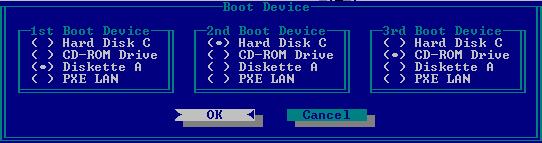
This menu allows the user to decide the order of boot devices to load the operating system. Bootable devices includes the distette drive in module bay, the onboard hard disk drive and the CD-ROM in module bay.
Exit
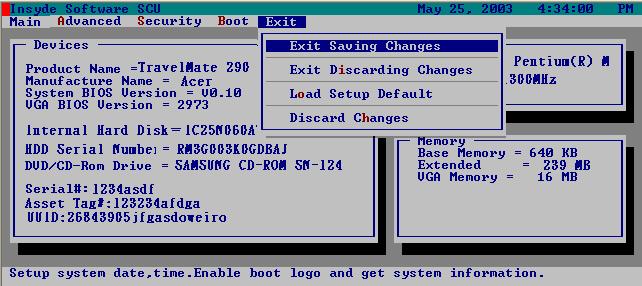
Parameter Description Exit Saving Changes Allows the user to save changes to CMOS and reboot the system. Exit Discarding Changes Allows the user Discards changes made and exits System Setup. Load Setup Default Loads default settings for all parameters (same as t ). Discard Changes Allows the user to discard previous changes in CMOS Setup.
The BIOS flash memory update is required for the following conditions: New versions of system programs New features or options Restore a BIOS when it becomes corrupted. Use the Flash utility to update the system BIOS flash ROM. NOTE: If you do not have a crisis recovery diskette at hand, then you should create a Crisis Recovery Diskette before you use the Flash utility. NOTE: Do not install memory-related drivers (XMS, EMS, DPMI) when you use the Flash utilities. NOTE: Please use the AC adaptor power supply when you run the Flash utility. If the battery pack does not contain enough power to finish BIOS flash, you may not boot the system because the BIOS is not completely loaded. Fellow the steps below to run the Flash. 1. Prepare a bootable diskette. 2. Copy the Flash utilities to the bootable diskette. 3. Then boot the system from the bootable diskette. The Flash utility has auto-execution function.
You can follow the steps below to clean BIOS and HDD password. 1. Copy clnpwd.exe to a bootable disc. 2. Boot from the disc and enter DOS mode. 3. Execute the utility by typing clnpwd. 4. The screen will display the following messages: Press 1-3 to clean any password shown as below 1. User Password 2. Supervisor Password 3. HDD Password 5. Press 1 if you want to clean user password; press 2 if you want to clean supervisor password; press 3 if you want to clean HDD password. 6. If the password has been successfully erased, the screen will display “Password clean successfully”, if not, the screen will show “The function is not supported by this platform”. 7. If the password has been removed, you can reboot your system. If not, please contact with your manufacturer.