
1 minute read
Separating the Upper Case from the Lower Case


NOTE: When connecting the cable back to the unit, please note that the cable should be routed well.
1. See “Removing the Battery Pack” on page 50. 2. See “Removing the SD dummy card” on page 51. 3. See “Removing the ExpressCard dummy card” on page 51. 4. See “Removing the Lower Cover” on page 52. 5. See “Removing the DIMM” on page 53. 6. See “Removing the WLAN Board Modules” on page 54. 7. See “Removing the Hard Disk Drive Module” on page 56. 8. See “Removing the Optical Drive Module” on page 58. 9. See “Removing the Middle Cover” on page 62. 10. See “Removing the Keyboard” on page 63. 11. See “Removing the Heatsink Fan Module” on page 64. 12. See “Removing the CPU Heatsink Module” on page 65. 13. See “Removing the CPU” on page 66. 14. See “Removing the LCD Module” on page 67.

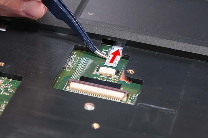
16. Disconnect the LED cable from LEDCN1 on the main board.

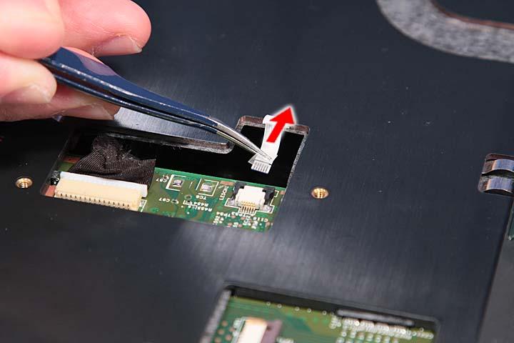
17. Disconnect the speaker cable from the INTSPK1 connector on the main board.

18. Remove the eleven screws (11 x A, 1 x G) from the bottom panel.
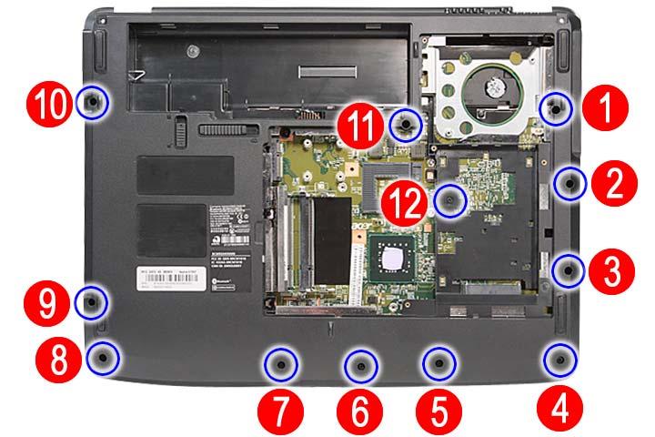
Step Size (Quantity) Color Torque 1~11 M2.5 x L8 (11) Black 3.0 kgf-cm 12 M2 x L4 (1) Black 3.0 kgf-cm

