1 minute read
Removing the Upper Cover


1. See “Removing the Battery Pack” on page 44. 2. See “Removing the SD dummy card” on page 45. 3. See “Removing the ExpressCard dummy card” on page 46. 4. See “Removing the Lower Covers” on page 47. 5. See “Removing the DIMM Modules” on page 49. 6. See “Removing the WLAN Module” on page 50. 7. See “Removing the Hard Disk Drive Module” on page 52. 8. See “Removing the Optical Drive Module” on page 55. 9. See “Removing the Switch Cover” on page 59. 10. See “Removing the Keyboard” on page 61. 11. See “Removing the LCD Module” on page 66. 12. Turn the computer over. Remove the eight screws on the bottom panel.
Step
Size
Upper Cover M2.5*8 (NL) 8
Quantity Screw Type

Step
Size
Upper Cover M2.5*5 (NL) 7
Quantity Screw Type
A B
E

C
D
Disconnect A as shown. Release the securing latches and disconnect B as shown.


Release the securing latches and disconnect C as shown. Release the securing latches and disconnect D as shown.


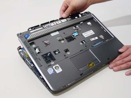
15. Remove the upper cover by lifting upward from the chassis, rear edge first.
16. Turn the upper cover over. The upper cover appears as follows.
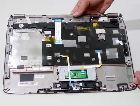
NOTE: Avoid pulling on the cables directly to prevent damage to the connectors. NOTE: Use the pull-tabs on the FFC cables whenever available to prevent damage to the FFC cables.