1 minute read
4–1 Checking Flexplate, Engine Features
from Allison Transmission MT1321EN AT 500 & AT 1500 Series Transmission Mechanic's Tips Manual - PDF
PREPARING VEHICLE FOR TRANSMISSION INSTALLATION
SECTION IV
4–1. CHECKING FLEXPLATE, ENGINE FEATURES
Transmission performance may be adversely affected by improper tolerances existing between engine-to-transmission mating components. The drive connection between the engine and transmission converter must transmit engine power, properly locate and pilot the torque converter, and aid in controlling the forward thrust of the converter.
Vibration, converter section fluid leaks, a worn front bushing or bearing, and/or a worn engine crankshaft thrust bearing are frequently the result of exceeding recommended tolerances in engine-to-transmission mating components. When these conditions are encountered, certain important measurements should be investigated before installing a repaired or new transmission.
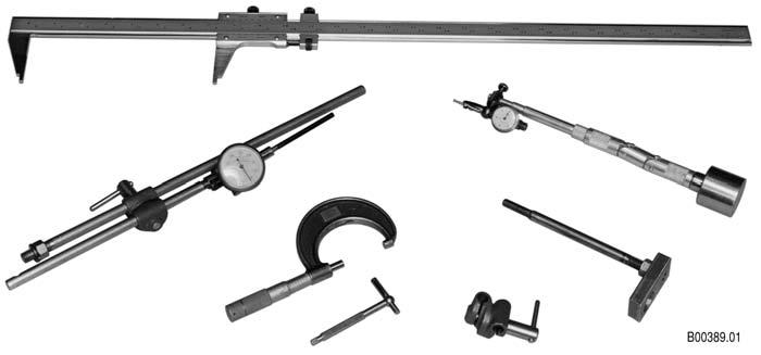
These measurements are summarized in Table 4–1. Figure 4–1 illustrates the tooling required for these measurements. Reference SIL 60-TR-81 (latest revision).
Figure 4–1.Tooling Used to Determine the Adaptation Measurements of an AT 500 Series Transmission
Component or Subassembly Required Inspections Limits
Flywheel Housing
Crankshaft Hub and/or Adapter
Flexplate
Mounted Flexplate Bore Diameter 16.125–16.130 in. (409.58–409.70 mm) Bore Eccentricity* 0.020 in. (0.51 mm) T.I.R. Face Squareness* 0.020 in. (0.51 mm) T.I.R. Converter Pilot Diameter 1.703–1.705 in. (43.26–43.31 mm) Face Squareness 0.0005 in. (0.013 mm) T.I.R.** Eccentricity† 0.010 in. (0.25 mm) T.I.R. Check for Radial Cracks None Permitted
Check for Elongated Mounting Holes Check for Any Signs of Distress and/or Wear None Permitted
None Permitted
Axial Location Flatness —AT 540/AT 542/
AT 545 models with converter build date stamp before 9/84 —AT 540/AT 542/
AT 545 models with converter build date stamp of 9/84 or later 1.600–1.740 in. (40.64–44.19 mm)
1.581–1.741 in. (40.16–44.22 mm)
—AT 543 models 1.600–1.721 in. (40.64–43.71 mm) —AT 1500 models 2.715–2.875 in. (68.96–73.03 mm)
Flatness —Formed Plates †† 0.039 in. (0.99 mm) —Flat Plates 0.157 in. (3.99 mm)
*Limits are for installed engines. **T.I.R. per inch of diameter. †Eccentricity with respect to crankshaft center of rotation. ††A formed flexplate will not be flat, but may have raised areas at the bolt holes and/or have offset bends in the plate.


