12 minute read
Chapter 3 Machine Disassembly and Replacement


Machine Disassembly and Replacement
This chapter contains step-by-step procedures on how to disassemble the notebook computer for maintenance and troubleshooting. To disassemble the computer, you need the following tools: Wrist grounding strap and conductive mat for preventing electrostatic discharge Philips screw drivers Flat head screwdriver NOTE: The screws for the different components vary in size. During the disassembly process, group the screws with the corresponding components to avoid mismatch when putting back the components. When you remove the middle cover, please be careful not to scrape the cover.
Before You Begin
Before proceeding with the disassembly procedure, make sure that you do the following: 1. Turn off the power to the system and all peripherals. 2. Unplug the AC adapter and all power and signal cables from the system. 3. Remove the battery pack. NOTE: TravelMate C310 series product uses tape to fasten the antenna/cable, you may need to tear the tape before you remove the antenna. NOTE: The disassembly is based on an engineering sample, therefore, the number of the screws may differ from what you would actually get.
The flowchart on the succeeding page gives you a graphic representation on the entire disassembly sequence and instructs you on the components that need to be removed during servicing. For example, if you want to remove the system board, you must first remove the then disassemble the inside assembly frame in that order.
Start
Battery
M3L4*1 M2.5L6*1
HDD Cover ODD Module Keyboard *1 *2
DIMM Cover Mini PCI Cover
HDD Module M2L3*4
ODD Bracket M2L8*3 M2L4*4
Hinge Covers Keyboard Support Plate Middle Cover
HDD Holder HDD Drive
Optical Drive
Optical Device Board
ODD Connector M2L4*2 Memory/ MDC board
RTC Battery
Disconnect Bluetooth
M2.5L5*4
LCD Module Memory (upgrade)
M2L4.5*2 Inverter
Button Board M2L4.5*2
LED Board
M2L4.5*2
Main Antenna M2L4.5*2 Wireless LAN Card
LCD Panel
Touchpad
Upper Assembly
Toucpad Cover
Touchpad Scroll Key Touchpad Button M2.5L6*2 M2L6*12
Lower case left cover
Lower Assembly
M2L4*2
Lower case right cover
M2L4*1
Main Board Assembly LCD/w cable, brakets
M2L3*8 for CMO
LCD Brackets LCD LCD Coaxial Cable
Touchpad Cable M2L4*2 M2L4*1 Speaker Module Extension Board *4
Heatsink Module CPU
Main Board
1. Release the battery lock. 2. Slide the battery latch then remove the battery.
Removing the HDD Module/Optical Module/Wireless LAN Card/Keyboard and LCD Module
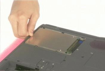
Removing the HDD Module
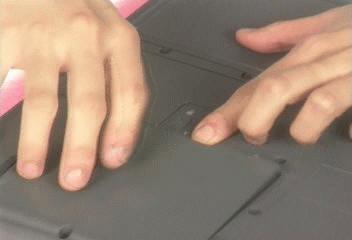
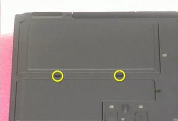
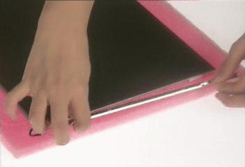
1. Remove the two screws holding the HDD cover. 2. Pull out the hard disk drive then detach it from the main unit.
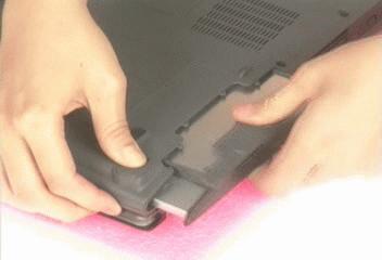
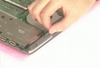
Removing the Optical Disc Drive Module
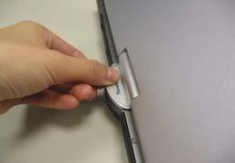
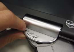
1. Slide the ODD latch then remove the ODD module from the main unit carefully.
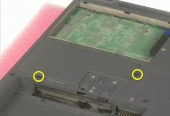
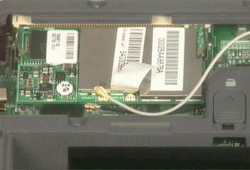
Removing the Wireless LAN Card
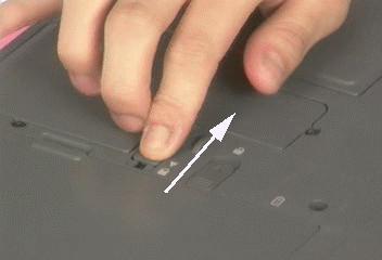
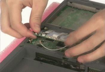
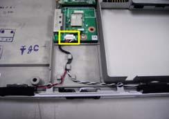
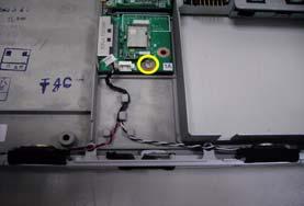
1. Remove the two screws that fasten the Mini PCI cover. 2. Disconnect the main and the auxiliary antenna. 3. Pop out the wireless LAN card then remove it.
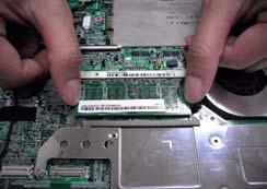
Removing the Memory
1. Remove the screw securing the RAM door and remove the RAM door.
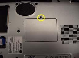
NOTE: The main memory is located on the top of the mainboard.
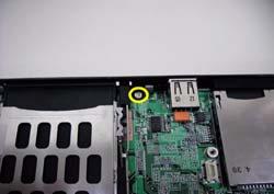
Removing the Keyboard
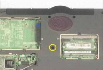
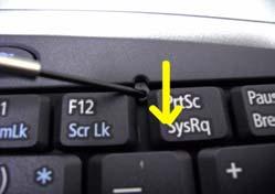
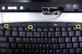
1. Remove the screw holding the keyboard. 2. Release the keyboard locks (x3). 3. Turn the keyboard over and disconnect the keyboard cable then remove the keyboard.
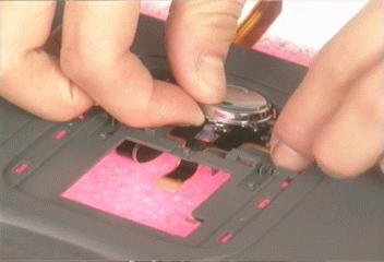
Removing the LCD Module
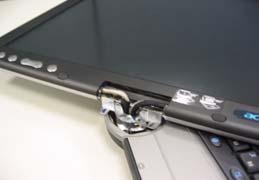
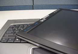
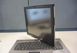
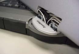
1. See “Removing the Keyboard” on page 50. 2. Rotate the LCD module clockwise 135 degree. 3. Press down the LCD module as picture shows. 4. Detach the front hinge cap carefully.
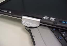
NOTE: Hinge caps disassembling SOP (step2-step7) is different from what you will see on the mepg files. You can disassemble either the front or the back hinge cap first as you like. Both methods are workable. 5. After detach the front hinge cap, erecat the LCD module as picture shows.
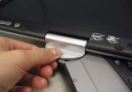
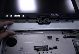
6. Rotate the LCD module counter-clockwise 90 degree. Then press down the LCD module a little bit. 7. Remove the back hinge cap carefully.
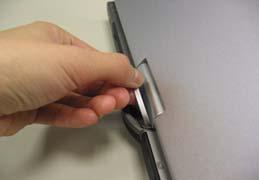
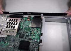
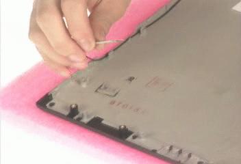
8. Detach the middle cover carefully.
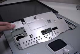
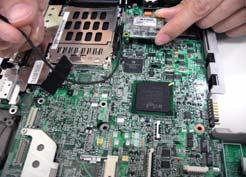
9. Remove the eight screws holding the keyboard support plate then remove the plate.
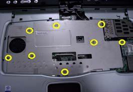
NOTE: This is an engineering sample. The number of screws holding the keyboard support plate maybe vary from the mass production units.
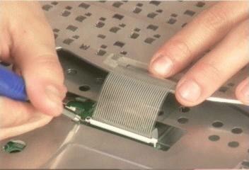
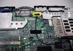
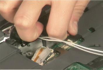
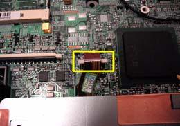
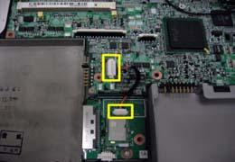
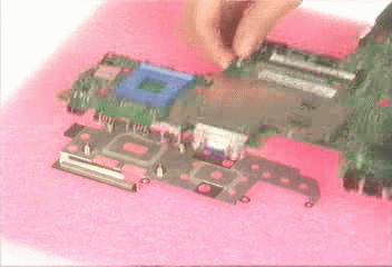
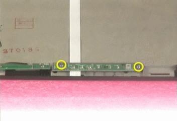
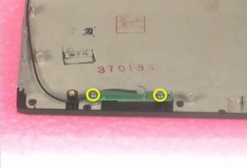
10. Disconnect the modem board cable from the mainboard. 11. Remove the modem board and cable.
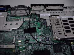
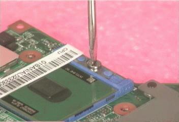
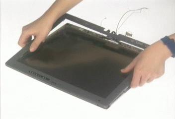
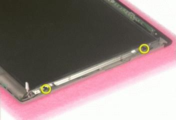
12. Remove the four screws fastening the LCD module; two on the front and another two on the back.
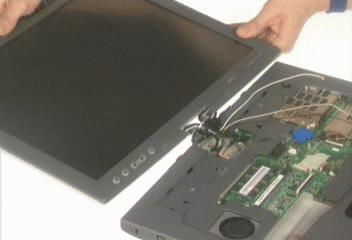
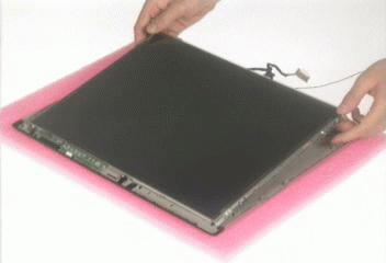
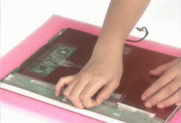
13. Place the LCD module as the picture shows carefully. 14. Disconnect the LCD coaxial cable and inverter cable respectively.
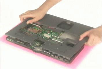
Separate the main unit into the logic upper and the logic lower assembly
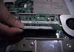
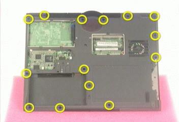
1. Pop out the memory then remove it from the DIMM socket. 2. Remove the 14 screws holding the upper case assembly and the lower case assembly.
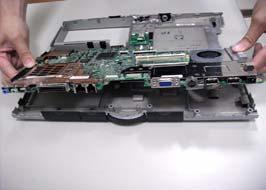
3. Disconnect touchpad cable connecting to the main board. 4. Separate the main unit into the upper case assembly and the lower case assembly.
Disassembling the logic upper assembly
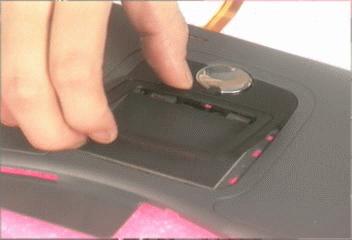
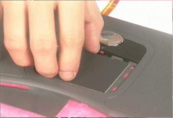
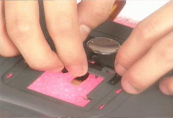
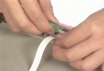
1. Disconnect the touchpad cable. 2. Tear off the touchpad cable.
NOTE: The touchpad cable has been fastened very tight to the upper case by black tape. It is easy tear the touchpad cable when removing the black tape. 3. Release the touchpad cover latches. 4. Detach the touchpad holder.
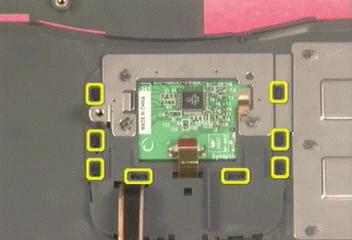
5. Remove the touchpad. 6. Detach the touchpad button. 7. Then detach touchpad scroll key.
Disassembling the logic lower assembly
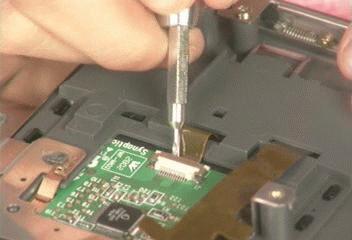
1. Remove the lower case left cover. 2. Remove the screw holding the lower case right cover. 3. Then remove the lower case right cover.
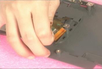
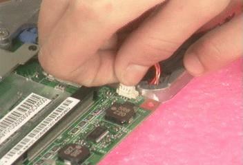
4. Disconnect the cable from mainboard to CD ROM board. 5. Disconnect the speaker cable.
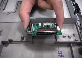
6. Take out the main board from the lower case. 7. Remove the screw securing the CD ROM board. 8. Take out the CD ROM board from the lower case.
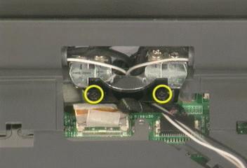
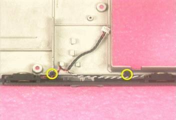
9. Remove the two screws that fasten the speaker module. 10. Disconnect the fan cable.
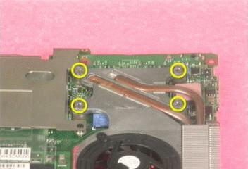
11. Remove the four screws that fasten the heatsink module then remove the heatsink module. 12. Release the CPU lock with a flat-head screwdriver then remove the CPU from the socket. 13. Take the main board off the thermal plate.
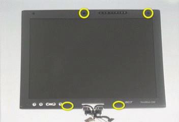
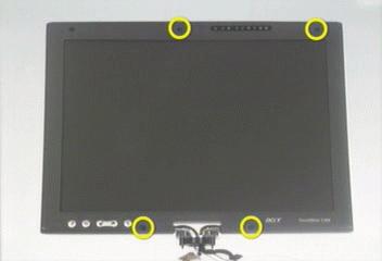
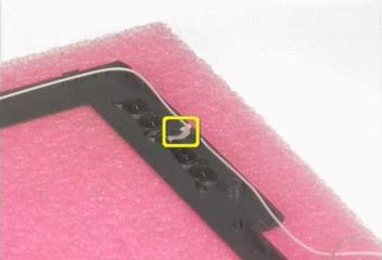
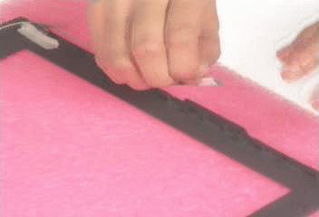
1. Remove the four LCD screw caps. 2. Then remove the four screws that secure the LCD bezel. 3. Detach the LCD bezel carefully.
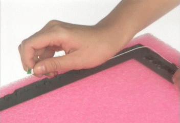
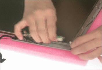
4. Tear off the tape fastening the bluetooth antenna. 5. Then remove the bluetooth antenna from the LCD bezel. 6. Then disconnect the LCD inverter cable.
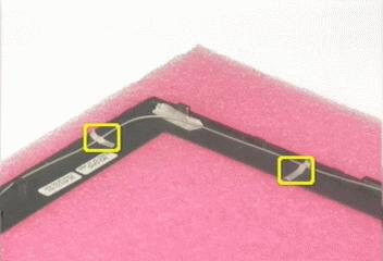
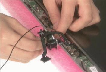
7. Remove the auxiliary wireless antenna. 8. Pull out the main wireless antenna, LCD coaxial cable and inverter cable. 9. Remove the two screws holding the inverter.
10. Disconnect the inverter cable then remove the inverter. 11. Remove the four screws that secure the LCD to the LCD panel; two on each side. 12. Take out the LCD from the LCD panel.
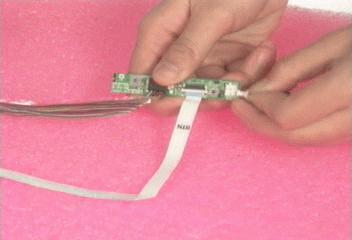
13. Remove the two screws holding the LED board. 14. Disconnect the LED board cable. 15. Remove the two screws that secure the button board.
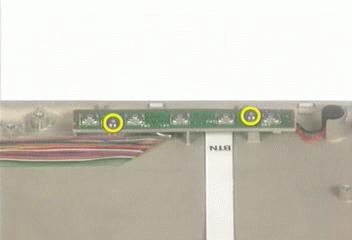
16. Take out the microphone, detach the button board assembly. 17. Disconnect the microphone, the LCD coaxial cable and the button board to LED board cable. 18. Tear off the tape fastening the main wireless antenna.
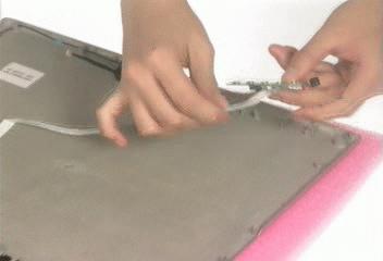
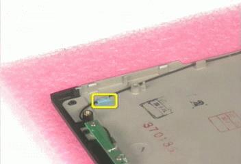
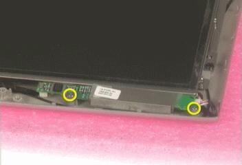
19. Remove the two screws holding the main wireless antenna. 20. Remove the main wireless antenna from the LCD panel. 21. Disconnect the LCD coaxial cable and detach the cable from the LCD.
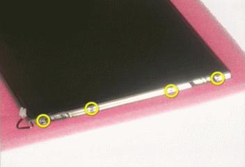
22. Remove the eight screws fastening the LCD brackets; four on each side. 23. Remove the right and the left LCD brackets.
Disassembling and Reassembling the HDD Module
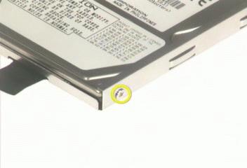
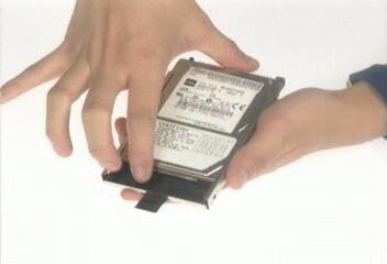
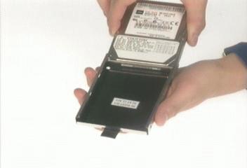
1. Remove the screw holding the HDD holder. 2. Take out the hard disc drive from the HDD holder carefully.
3. Place the hard disc drive back to the HDD holder. 4. Secure the hard disc drive to the HDD holder witht the screw as shown.
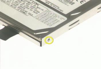
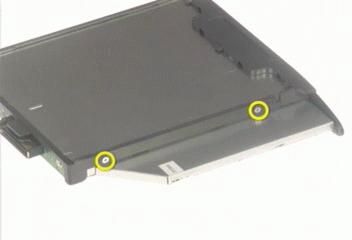
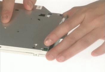
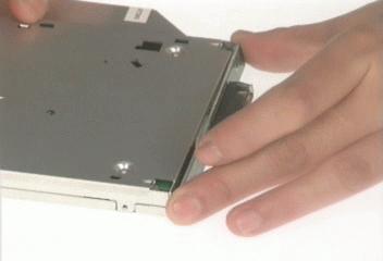
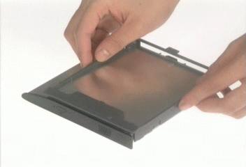
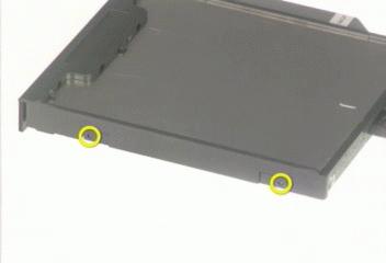
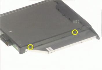
1. Remove the two screws holding the optical bracket. 2. Remove another two screws as shown. 3. Then remove the optical bracket.
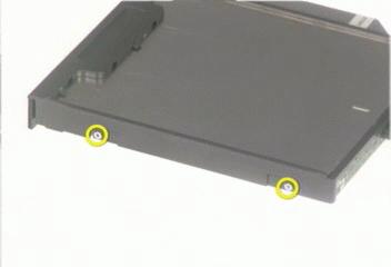
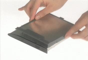
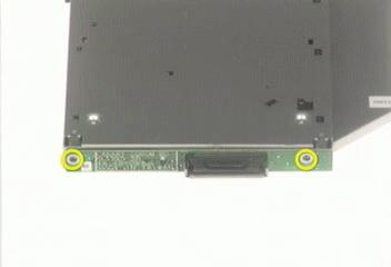
4. Remove the two screws holding the optical board. 5. Remove the optical device board. 6. Reattach the optical device board to the optical disc drive.
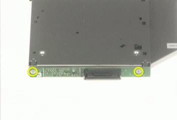
7. Secure the optical device board with two screws as shown. 8. Attach the optical bracket back to the ODD.
9. Secure the optical bracket with the two screws as shown. 10. Then fasten the optical braket with another two screws as shown.
1. Rotate the LCD module clockwise 135 degree. Press down the LCD module as picture shows. 2. Place the front hinge cap back to its original position. 3. Press the front hinge cap until you hear a click.
4. After attach the front hinge cap, erecat the LCD module as picture shows. 5. Rotate the LCD module counter-clockwise 90 degree. Then press down the LCD module a little bit. 6. Place the back hinge cap back the unit as picture shows.