15 minute read
Chapter 2 System Utilities


System Utilities
BIOS Setup Utility
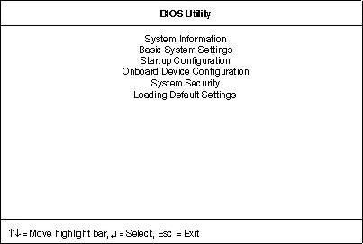
The BIOS Setup Utility is a hardware configuration program built into your computer’s BIOS (Basic Input/ Output System). Your computer is already properly configured and optimized, and you do not need to run this utility. However, if you encounter configuration problems, you may need to run Setup. Please also refer to Chapter 4 Troubleshooting when problem arises. To activate the BIOS Utility, press F2 during POST (while the TravelMate logo is being displayed).
Navigating the BIOS Utility
There are six menu options: System Information, Basic System Settings, Startup Configuration, Onboard Device Configuration, System Security and Loading Default Settings. To enter a menu, highlight the item using the cursor up/down keys, then press Enter. Within a menu, navigate through the BIOS Utility by following these instructions: Press the cursor up/down keys to move between the parameters. Press the cursor left/right keys to change the value of a parameter. Press the Esc key while you are in any of the menu options to return to the main menu.
NOTE: You can change the value of a parameter if it is enclosed in square brackets. Navigation keys are shown at the bottom of the screen.
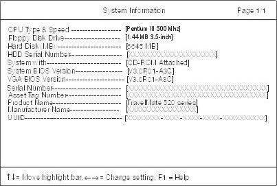
The System Information screen displays a summary of your computer hardware information.
NOTE: The screen above is a sample and may not reflect the actual data on your computer. “X” may refer to a series of numbers and/or characters.
The following table describes the information in this screen.
The items in this screen are important and vital information about your computer. If you experience computer problems and need to contact technical support, this data helps our service personnel know more about your computer.
Parameter Description
CPU Type & Speed Describes the type of CPU installed in the system. Floppy Disk Drive Shows the floppy disk drive type (1.44 MB, 3.5-inch). Hard Disk Drive Shows the size or capacity of the hard disk. HDD Serial Number Shows the serial number of the hard disk. System with Shows the high-capacity disc drive installed. System BIOS Version Shows the system BIOS version. VGA BIOS Version Shows the video graphics accelerator BIOS version. Serial Number Shows the serial number of the computer. Asset Tag Number Shows the asset tag number of the computer. Product Name Shows the official name of the product. Manufacturer Name Shows the manufacturer of the computer. UUID Shows the universally unique identifier of your computer.
The Basic System Settings screen allows you to set the system date and time.
The following table describes the parameters in this screen.

Parameter Description Format
Date Sets the system date. DDD MMM DD, YYYY (day-of-the-week month day, year) Time Sets the system time. HH:MM:SS (hour:minute:second)
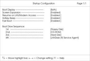
Startup Configuration
The Startup Configuration screen contains parameter values that define how your computer behaves on system startup.
The following table describes the parameters in this screen. Settings in boldface are the default and suggested parameter settings.
Parameter
Description
Boot Display Sets the display device on boot-up. When set to Auto, the computer automatically determines the display device when the computer starts up. If an external display device (e.g., monitor) is connected, it becomes the boot display; otherwise, the computer’s display screen is the boot display. When set to Both, the computer outputs to both the computer display screen and an external display device if one is connected. Screen Expansion When set to enabled, the screen will automatically adjust the display to fit the screen when the resolution is set to 640 x 480.
Resume on LAN/Modem Access When enabled, it allows your computer to resume when LAN/Modem access is active.
Hotkey Beep When enabled, the computer gives off a beep when a hotkey (key combination is pressed). Fast Boot Allows you to define your system’s booting process; whether to skip some POST routines or proceed with the normal booting process. Boot Drive Sequence Specifies the order in which the computer starts up from. See the section below. 1st: Floppy Disk, 2nd: CD-ROM, 3rd: Hard Disk 4th: LANDesk (R) Service Agent
Options
Both or Auto
Enabled or Disabled
Enabled or Disabled
Enabled or Disabled
Enabled or Disabled
Setting the Boot Drive Sequence
The Boot Drive Sequence section lists boot priorities (1st, 2nd, 3rd and 4th) for bootable drives in your computer.
For example, the default value (1st:Floppy Disk, 2nd:CD-ROM, 3rd:Hard Disk and 4th:LANDesk (R) Service
Agent) tells the computer to first search for a bootable floppy disk in the floppy drive. If it finds one present, it boots up from that floppy disk. If not, the computer continues to search for a bootable CD-ROM in the CD-
ROM drive. If it cannot boot up from the CD-ROM drive, it continues by booting up from the hard disk.
To set the boot drive sequence, use the cursor up/down keys to select a priority level (1st, 2nd, 3rd and 4th), then use the cursor left/right keys to select the device for that priority level.
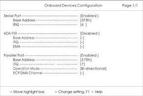
The parameters in this screen are for advanced users only. You do not need to change the values in this screen because these values are already optimized. The Onboard Device Configuration screen assigns resources to basic computer communication hardware.
The following table describes the parameters in this screen. Settings in boldface are the default and suggested parameter settings.
Parameter
Description
Serial Port Enables or disables the serial port. When enabled, you can set the base I/O address and interrupt request (IRQ) of the serial port.
IrDA FIR Port Enables or disables the infrared port. When enabled, you can set the base I/O address and interrupt request (IRQ) and direct memory access (DMA) channel of the infrared port. Parallel Port Enables or disables the parallel port. When enabled, you can set the base I/O address, interrupt request (IRQ) and operation mode of the parallel port. If operation mode is set to ECP, the direct memory access (DMA) channel of the parallel port is set to 1.
Options
Enabled or Disabled 3F8h, 3E8h, 2F8h or 2E8h 4 or 11 Disabled or Enabled
Enabled or Disabled 378h, 278h, or 3BCh 7 or 5 Bi-directional, ECP, EPP or Standard
The System Security screen contains parameters that help safeguard and protect your computer from unauthorized use.
The following table describes the parameters in this screen. Settings in boldface are the default and suggested parameter settings.
Setting a Password
Follow these steps: 1. Use the cursor up/down keys to highlight a Password parameter (Setup, Power-on or Hard Disk) and press the Enter key. The password box appears:
2. Type a password. The password may consist of up to eight characters (A-Z, a-z, 0-9).
IMPORTANT:Be very careful when typing your password because the characters do not appear on the screen. 3. Press Enter. Retype the password to verify your first entry and press Enter. 4. After setting the password, the computer automatically sets the chosen password parameter to Present.
Parameter
Description
Setup Password When set, this password protects the computer and the BIOS Utility from unauthorized entry. See the following section for instructions on how to set a password. Power-on Password When set, this password protects the computer from unauthorized entry. See the following section for instructions on how to set a password. Hard Disk Password When set, this password protects the hard disk from unauthorized access. See the following section for instructions on how to set a password. Processor Serial Number The Pentium III processor includes a unique serial number which allows individual CPUs to be identified. You can turn off this feature by setting this parameter to Disabled. This one is not available in the model with Celeron processor.
Options
None or Present
None or Present
None or Present
Enabled or Disabled
Three password types protect your computer from unauthorized access. Setting these passwords creates several different levels of protection for your computer and data: Setup Password prevents unauthorized entry to the BIOS Utility. Once set, you must key-in this password to gain access to the BIOS Utility. Power-On Password secures your computer against unauthorized use. Combine the use of this password with password checkpoints on boot-up and resume from hibernation for maximum security. Hard Disk Password protects your data by preventing unauthorized access to your hard disk. Even if the hard disk is removed from the computer and moved to another computer, it cannot be accessed without the Hard Disk Password. When a password is set, a password prompt appears on the left-hand corner of the display screen. 1. When the Setup Password is set, the following prompt appears when you press F2 to enter the BIOS
Utility at boot-up.
Type the Setup Password and press Enter to access the BIOS Utility. 2. When the Power-on Password is set, the following prompt appears at boot-up.
Type the Power-on Password (a symbol appears for each character you type) and press Enter to use the computer. If you enter the password incorrectly, an x symbol appears. Try again and press Enter. 3. When the Hard Disk Password is set, the following prompt appears at boot-up.
Type the Hard Disk Password (a symbol appears for each character you type) and press Enter to use the computer. If you enter the password incorrectly, an x symbol appears. Try again and press Enter. You have three chances to enter a password. If you successfully entered the password, the following symbol appears.
If you fail to enter the password correctly after three tries, the following message or symbol appears.
To change a password, follow the same steps used to set a password. To remove a password, follow the same steps used to set a password, except type nothing in the password boxes.
If you want to restore all parameter settings to their default values, select this menu item and press Enter. The following dialog box displays.
If you would like to load default settings for all parameters, use the cursor left/right (→←) keys to select Yes; then press Enter. Choose No if otherwise.
The BIOS flash memory update is required for the following conditions: New versions of system programs New features or options Use the AFlash utility to update the system BIOS flash ROM. NOTE: Do not install memory-related drivers (XMS, EMS, DPMI) when you use AFlash. NOTE: This program contains a readme.txt file. This readme.txt file will introduce on how to use AFlash utility.
Executing Flash Program
IMPORTANT:If this diskette is not bootable, do the following actions before you use it: 1. Create a bootable disk. 2. Copy all AFlash files into this bootable diskette. 3. Put the bootable disk into TravelMate 520 series module, then reboot.
IMPORTANT:Never turn off the system power while Flash BIOS is programming. This will damage your system. 4. After Flash BIOS is done, reboot the system. NOTE: If there are any problems occurred during BIOS update, see “Index of PQA Diagnostic Error Code, Message” on page 81 for troubleshooting.
This utility diskette is for the Acer TravelMate 520 notebook machine. It provides the following functions: 1. Panel ID Utility 2. Thermal & Fan Utility 3. Main Board Data Utility To use this diskette, first boot from this diskette, then a “Microsoft Windows 98 Startup Menu” prompt you to choose the testing item. Follow the instructions on screen to proceed. NOTE: This program contains a readme.txt file. This readme.txt file will introduce each test utility and its functions.
IMPORTANT:If this diskette is not bootable, do the following actions before you use it: 1. Do system transfers. 2. Copy the following files to A:\.
HIMEM.SYS
RAMDRIVE.SYS
Panel ID Read/ Write Utility
1. Panel ID Read This function will display the panel ID setting of Acer TravelMate 520 series, there maybe no values in inverter if no ID was found. 2. Panel ID Write This function will display a table of all panel IDs of Acer TravelMate 520 series, and ask to input the no. corresponding to the panel ID of the LCD. Then, the chosen ID will be set in EEPROM.
Thermal test Utility
1. Read thermal setting This function will show the current thermal setting of your system and CPU which include the status, current local temp, remote temp, conversion and configuration. 2. Set thermal setting This function will write the default values into EEPROM. 3. Test fan This function will test the fan. Error message will be displayed when problem is found.
Main Board Data Utility
1. Read Main Board Data. This function displays the MBD data. 2. Create MBD header, product & manufacturer names. This function will create three informations and write to EEPROM automatically: a. Header information b. Product name c. Manufacturer name 3. Write MBD UUID There are two sub-functions: a. Create and write a new UUID - this function is used when the original UUID is lost or damaged.
b. Write UUID by user keyin - this function is used when the original UUID is kept. User may use “Read Main Board Data” function first to keep the UUID. 4. Write MBD serial number - this function will write MBD serial number by user keyin.
IMPORTANT: 1The diagnostics program here that we used is called PQA (Product Quality Assurance) and is provided by Acer Headquarters. You can utilize it as a basic diagnostic tool. To get this program, either download it from http://csd.acer.com.tw or find it in the TravelMate 520 service CD kit. To better fit local service requirements, your regional office MAY have other diagnostic program. Please contact your regional offices or the responsible personnel/channel to provide you with further technical details. NOTE: This program contains a readme.txt file. This readme.txt file will introduce each test and its functions. This diagnostic program is designed to perform the following diagnostic tools for Acer TravelMate 520 notebook machine. It provides the following functions. 1. PQA System Diagnostics 2. Audio Resource and Loopback Test 3. IR Test 4. USB Register and Connect/ Disconnect Test To use this diskette, first boot from this diskette, then a “Microsoft Windows 98 Startup Menu” prompts you to choose the testing item. Follow the instructions on screen to proceed. IMPORTANT:If this diskette is not bootable, do the following actions before you use it: 1. Do system transfers. 2. Copy the following files to A:\
HIMEM.SYS
RAMDRIVE.SYS
CHOICE.COM
MSCDEX.EXE
PQA System Diagnostics
NOTE: This PQA diagnostics program will test Acer TravelMate 520 notebook series’ hardware peripherals. 1. When you select One Test, Test command (F2 key) will only work in the first-level menu (Item Test), if you are in sub-level menu, please press ESC to return to upper-level (Item Test) menu. 2. Use Space Bar to select/ deselect a testing item. 3. When testing is done, there will be a testing report, where you could find out whether the testing is successful or not.
Audio Resource and Speaker-Out Test
This function will test Audio Resource and Loopback of Acer TravelMate 520 notebook series. You will see “PASS” when test is successful. You need “Loopbacker” when you choose “Loopback Test”. Please put Loopbacker in Line-in, Line-out and Micro-in. You will see “PASS” when test is successful.
Infrared Ray (IR) Test
This function will test Infrared Ray of Acer TravelMate 520 series. Following are the steps: 1. You must prepare a reflect server (another Acer TravelMate 520 notebook) which can reply to testing unit the communicated data. 2. Prepare a bootable disk for the server, choose “Make a Host Disk” . 3. Insert the Host disk in Host Server, then reboot.
4. Type “Host” to run Host server first. 5. If there is no reflect server, the test program will show “IR FAIL” .
USB Register and Connect/ Disconnect Test
This function will test USB Register and Connect/Disconnect of TravelMate 520 notebook series. 1. Register test (USBCMD, USBINTR, FRNNUM, FLBASEADD, SOF) - test its own USB internal circuit. 2. UHCI/ OHCI test utility a. Please prepare a USB device such as USB mouse, USB keyboard or USB modem, and leave the USB port disconnected. (Don’t connect first) b. Program will dynamically detect the incoming device for two times, please plug the USB connector in USB port first, then plug it out. (Connect one time, disconnect one time) c. The test program will show the account of connected/ disconnected, if every steps was doing right, the screen will show “PASS”, otherwise show “FAIL” .
Running PQA Diagnostics Program
PQA Vx_x xx-xx-xx
Diag Result SysInfo Option Exit
PQA Vx_x xx-xx-xx
Diag Result SysInfo Option Exit Diag
Press →← to move around the main menu. Press Enter to enable the selected option. The main options are Diag, Result, SysInfo, Option and Exit. The Diag option lets you select testing items and times. The following screen appears when you select Diag from the main menu.
One Test performs a single test and Manual checks the selected test items in sequence. Multi Test performs multiple tests of the selected items and check the selected test items in sequence.
ONE TEST MULTI TEST FULL TEST QUICK TEST
Full Test performs all test items in detail for your system. Quick Test performs all test items quickly for your system. The screen below appears if you select Multi Test.
PQA Vx_x xx-xx-xx PQA Vx_x xx-xx-xx
Diag Diag Result Result SysInfo SysInfo Option Option Exit Exit
Diag One TEST Multi TEST Diag ONE TEST MULTI TEST FULL TEST
QUICK TEST
TEST COUNT VALUE (1...9999) 1
Specify the desired number of tests and press Enter. After you specify the number of tests to perform, the screen shows a list of test items (see below).
PQA Vx_x xx-xx-xx
DiagDiag Result SysInfo Option Exit
MANUAL TESTTest Items AUTO TEST[ ] System Board [ ] Memory [ ] Keyboard [ ] Video [ ] Parallel Port [ ] Serial Port [ ] Diskette Drive [ ] Hard Disk [ ] CD-ROM [ ] Coprocessor [ ] Pointing Dev. [ ] Cache SPACE: mark/unmark selecting item ESC : return to upper menu
F2 : test the marked item(s) ENTER: open sub-item’s menu Test Times = 1
Move the highlight bar from one item to another. Press Space to enable or disable the item. Press Enter to view the available options of each selected item. Press Esc to close the submenu. The right corner screen information gives you the available function keys and the specified test number. Space: Enables/disables the item ESC: Exits the program F1: Help F2: Tests the selected item(s) Enter: Opens the available options Test Times: Indicates the number of tests to perform. NOTE: The F1 and F2 keys function only after you finish configuring the Test option. NOTE: When any errors are detected by diagnostic program, refer to “Index of PQA Diagnostic Error Code, Message” on page 81 for troubleshooting.