1 minute read
Removing the LCD with Brackets


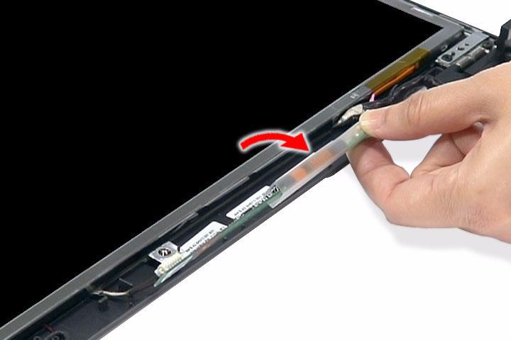
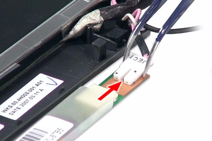
14. Disconnect the inverter board cable from its connector, then disconnect the 2P cable on the inverter board.
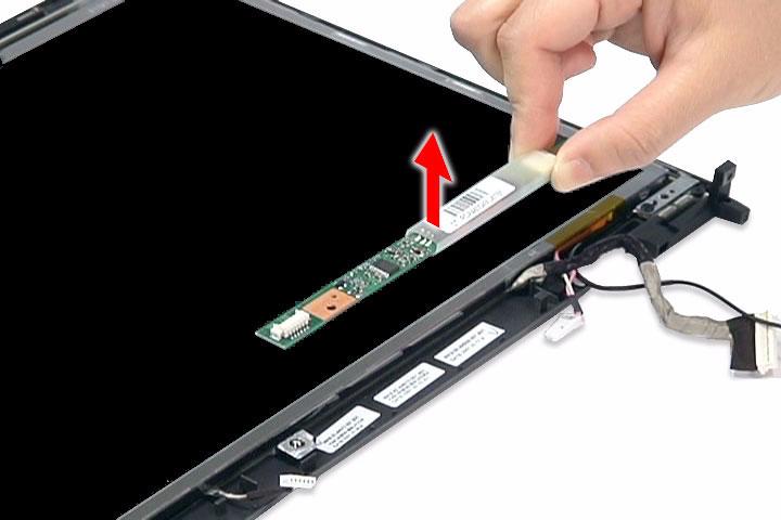
15. Remove the inverter board.
1. See “Removing the Battery Pack” on page 51. 2. See “Removing the SD Dummy Card” on page 51. 3. See “Removing the Express Dummy Card” on page 52. 4. See “Removing the Lower Cover” on page 53. 5. See “Removing the Fan Module” on page 60. 6. See “Removing the CPU Heatsink Module” on page 61. 7. See “Removing the CPU” on page 62. 8. See “Removing the Middle Cover” on page 64. 9. See “Removing the Keyboard” on page 65. 10. See “Removing the LCD Module” on page 66. 11. See “Removing the LCD Bezel” on page 82.
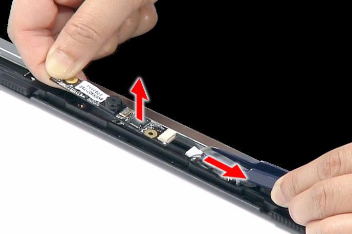
12. See “Removing the Inverter Board” on page 83. 13. Detach the CCD board cable from the CCD board, then remove the board.
14. Remove the two screws (I) securing the left and right LCD brackets to the LCD back cover.
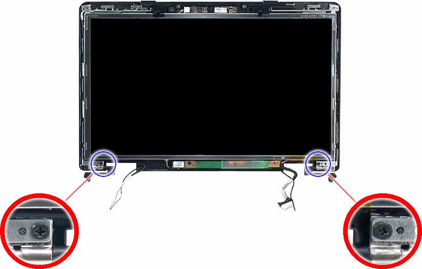
Step Size (Quantity) Color Torque
1~2 M2.5 x L5 (2) Silver 2.5 kgf-cm
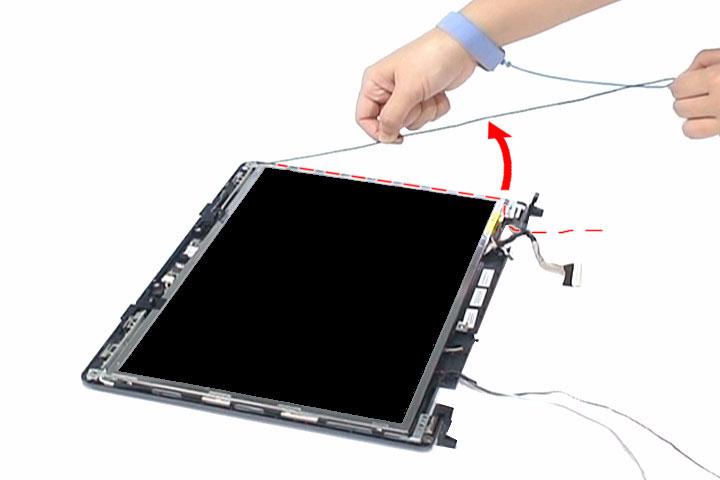
15. Carefully detach the cables from the latches on the LCD bracket as shown.
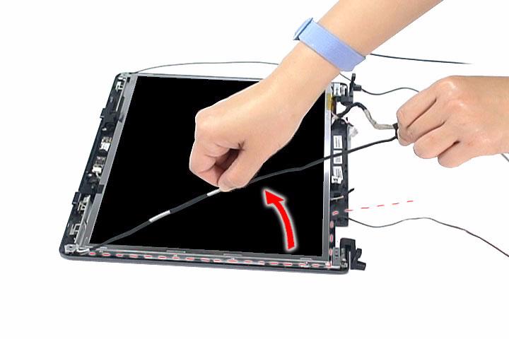
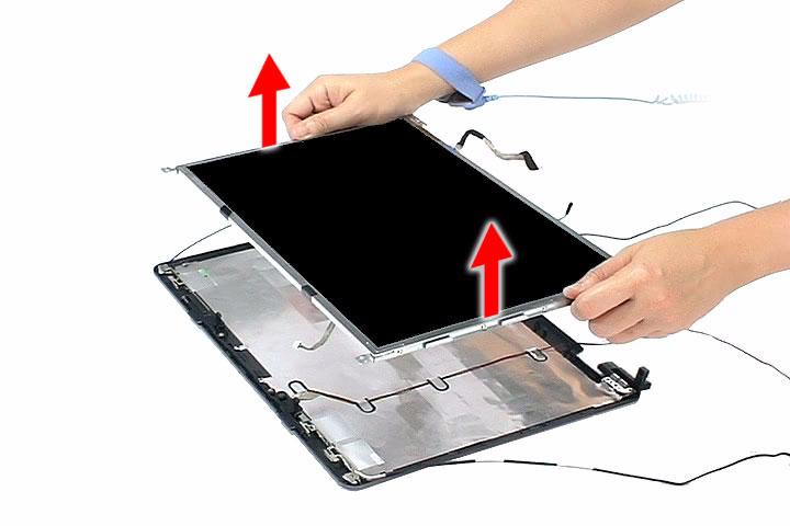
16. Detach the LCD with the brackets from the back cover.