5 minute read
Dimension and Weight


• 430 (W) x 335 (D) x 70 (H) mm with bezel, feet and WLAN antenna • Weight: 5.5 Kg
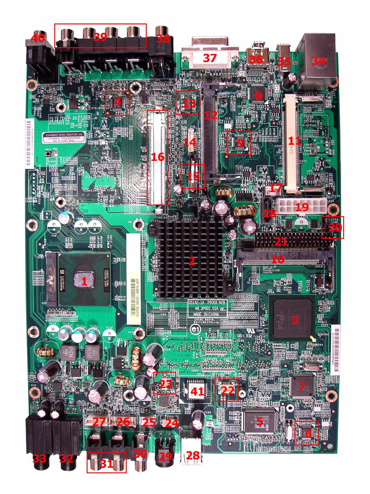

No. Description No. Description
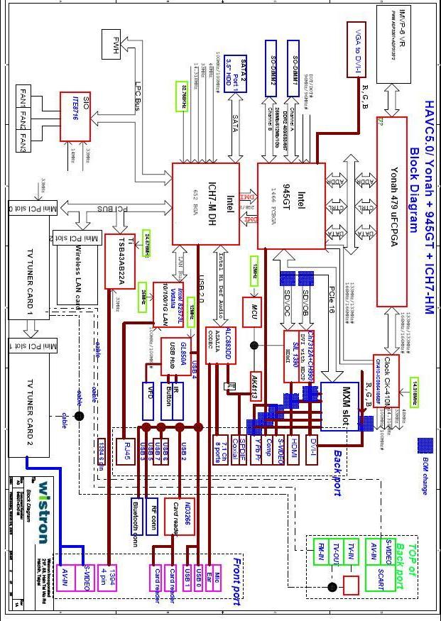
1 CPU socket 2 North bridge 3 South bridge 4 Azalia codec: Realtek ALC883DD 5 Super I/O controller: ITE8716F 6 USB hub: GL850A 7 IEEE 1394: Ti TSB43AB22A 8 Transmitter for HDMI: Silicon Image 1390 9 Transmitter for DVI-I: Chrontel 7313A 10 Mini PCI 1 slot for TV tuner card 1 11 Mini PCI 2 slot for TV tuner card 2 12 Mini PCI 3 slot for WLAN card 13 YPbPr to main board connector 14 SCART to main board connector 15 Battery 16 MXM connector (optional) 17 System fan connector 18 SATA connector 19 14-pin power connector 20 Jumper connector 21 PATA connector 22 Card reader connector 23 Bluetooth connector 24 IR connector 25 CPU fan connector 26 VFD board connector 27 Power button connector 28 USB 2.0 ports 29 S-Video input jack 30 Video input jack 31 Audio input jack 32 1/4” microphone jack 33 1/4” headphone jack 34 RJ-45 port and two USB 2.0 ports 35 6-pin IEEE1394 port 36 USB 2.0 port 37 DVI-I connector 38 Video output jack and S-Video output jack
39 Multi-channel speaker audio output connectors 40 Coaxial digital audio output jack
41 BIOS chip: PMC PM49FL004T 42 Clock generator 43 soDIMM slot 44 soDIMM slot

No. Component Description
1 Power button Press to power on or power off the system. 2 RF (radio frequency) receiver Receives radio frequency from wireless touchpad keyboard. 3 Drive eject button Ejects the optical disk. 4 Multi writable DVD drive Use to access and record data on compact disks (CDs) and digital video disks (DVDs) 5 IR (Infrared) receiver Receives IR signals from the remote control. 6 Playback controls Lets you conveniently play, record, pause, stop, forward, rewind, skip, or replay a song, slide show, movie or TV program.
7 VFD (Vacuum Fluorescent display) Displays the current Media Center status, current system date and time, or media title display.
8 MCE (Media Center Edition) navigation buttons
• 8A: Press the Back button to return to the previous view. • 8B: Press the Left, Right, Up, or Down arrow buttons to navigate through the Media Center menu options. • 8C: Press the OK button to access the Media Center menu options and confirm your selection. 9 I/O ports cover release button Press to open the I/O ports cover.
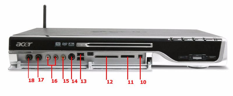
No. Component Description
10 4-pin IEEE 1394 port Connects to an IEEE 1394 device (e.g., digital video camcorder). 11 XD/SD/MMC/MS/MS PRO slot Accepts an XD (eXtreme Digital), SD (Secure Digital), MMC (MultiMediaCard), MS (Memory Stick) or MS PRO (Memory Stick PRO) card.
Warning!If you want to read contents from small form factor memory cards, such as mini-SD, RS-MMC, or MS PRO, you should use a suitable adaptor.
12 CF-I/CF-II/MD slot Accepts a CF (Compact Flash) Type I, CF Type II or Microdrive. 13 USB 2.0 ports Connects to USB peripherals devices (e.g., USB mouse, USB printer, USB combo drive, digital cameras). 14 S-Video input jack Connects to a video recorder, camcorder, or a device with S-Video output signal. 15 Video input jack Connects to a video recorder, camcorder, game console or a device with video output signal. 16 Audio input jack Connects t a video recorder, camcorder, audio casette player or stereo walkman. 17 1/4” microphone jack Connects to a microphone. 18 1/4” headphone Connects to a headphone.
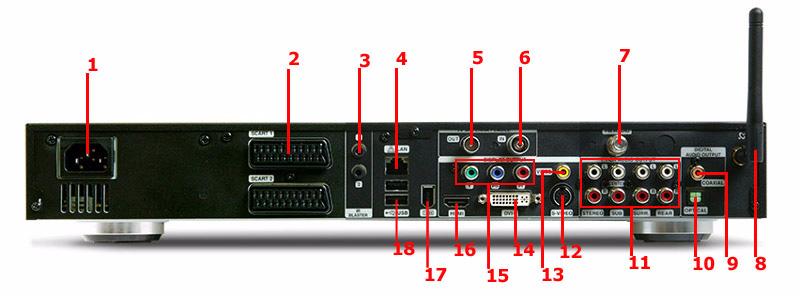
No. Component Description
1 Power connector Plug the power cable into this connector. 2 SCART input connector Connects to a set-top box or another A/V device. The SCART input connector supports Video, SVideo and Audio (L and R) input signals. SCART input/output connector Connects to a TV or a set-top box. The SCART input/output connector supports Video, S-Video, Audio (L and R) input and Composite Video and Audio (L and R) output signals. 3 IR blaster ports Connects an IR blaster to the set-top-box’s IR sensor window. 4 LAN port Connects to an Ethernet 10/100/1000MB based network 5 TV antenna/cable output jack Connects to a television. 6 TV antenna/cable input jack Connects to an antenna or cable TV. 7 FM radio input jack Connects to an external FM radio antenna. 8 WLAN antenna connector Connects to a wireless LAN antenna. 9 Coaxial digital audio output jack Connects to a digital device, such as MiniDisc 10 Optical digital audio output jack recorders, home theater receivers, or A/V receivers.
11 Multi-channel speaker audio output connectors
Connects to an amplifier which has multi-channel audio system. 12 Video output jack Connects to a TV with video output. 13 S-Video output jack Connects to a TV with S-Video input. 14 Component video output jack Connects to a TV with YPbPr input. 15 DVI-I connector Connects to a TV or LCD with DVI input or use the DVI-to-VGA adapter to connect a TV or monitor with VGA (D-Sub) input. 16 HDMI Connects to a TV with HDMI input. 17 6-pin IEEE 1394 port Connects to an IEEE 1394 device (e.g., digital video camcorder, hard disk, scanners). 18 USB 2.0 ports Connects to USB peripherals devices (e.g., USB mouse, USB printer, USB drive).
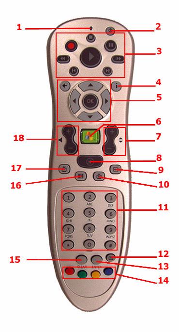
No. Component Description
1 Power LED Indicates that a command button is pressed. 2 Sleep Press to turn system to standby (sleep) mode. While in standby (sleep) mode, press the button again to wake up or activate the system. 3 Playback controls Lets you play, record, pause, stop, forward, rewind, skip or replay a song, slide show, movie or a TV program. 4 More Info Displays more information regarding the active TV program, video, album, or pictures.