18 minute read
System Utilities


Phoenix BIOS Setup Utility
BIOS setup is a hardware configuration program built into the system's Basic Input/Output System (BIOS). Since most systems are already properly configured and optimized, there is no need to run this utility. You will need to run this utility under the following conditions. When changing the system configuration settings When redefining the communication ports to prevent any conflicts When modifying the power management configuration When changing the password or making other changes to the security setup When a configuration error is detected by the system and you are prompted ("Run Setup" message) to make changes to the BIOS setup NOTE: If you repeatedly receive Run Setup messages, the battery may be bad. In this case, the system cannot retain configuration values in CMOS. Ask a qualified technician for assistance. BIOS setup loads the configuration values in a battery-backed nonvolatile memory called CMOS RAM. This memory area is not part of the system RAM which allows configuration data to be retained when power is turned off. Before you run the PhoenixBIOS Setup Utility, make sure that you have saved all open files. The system reboots immediately after you close the Setup. NOTE: PhoenixBIOS Setup Utility will be simply referred to as "Setup" or "Setup utility" in this guide.
The screenshots used in this guide display default system values. These values may not be the same those found in your system.
1. Turn on the server and the monitor.
If the server is already turned on, close all open applications, then restart the server. 2. During POST, press Delete.
If you fail to press Delete before POST is completed, you will need to restart the server.
The Setup Main menu will be displayed showing the Setup’s menu bar. Use the left and right arrow keys to move between selections on the menu bar.
Navigating Through the Setup Utility
Use the following keys to move around the Setup utility. Left and Right arrow keys – Move between selections on the menu bar. Up and Down arrow keys – Move the cursor to the field you want. PgUp and PgDn keys – Move the cursor to the previous and next page of a multiple page menu. Home – Move the cursor to the first page of a multiple page menu. End – Move the cursor to the last page of a multiple page menu. + and - keys – Select a value for the currently selected field (only if it is user-configurable). Press these keys repeatedly to display each possible entry, or the Enter key to choose from a pop-up menu. NOTE: Grayed-out fields are not user-configurable. Enter key – Display a submenu screen. NOTE: Availability of submenu screen is indicated by a (>). Esc – If you press this key: On one of the primary menu screens, the Exit menu displays. On a submenu screen, the previous screen displays. When you are making selections from a pop-up menu, closes the pop-up without making a selection. F1 – Display the BIOS setup General Help panel. F5 – Press to load previous default system values. F6 – Press to load fail-safe default system values. F7 – Press to load optimized default system values. F10 – Save changes made the Setup and close the utility.
The tabs on the Setup menu bar correspond to the six primary BIOS Setup menus, namely: Product Information Standard CMOS Features Advanced BIOS Features Advanced Chipset Features Integrated Peripherals Power Management Setup PnP/PCI Configurations PC Health Status Load Default Settings Set Supervisor Password Set User Password Save & Exit Setup Exit Without Saving In the descriptive table following each of the menu screenshots, settings in boldface are the default and suggested settings.
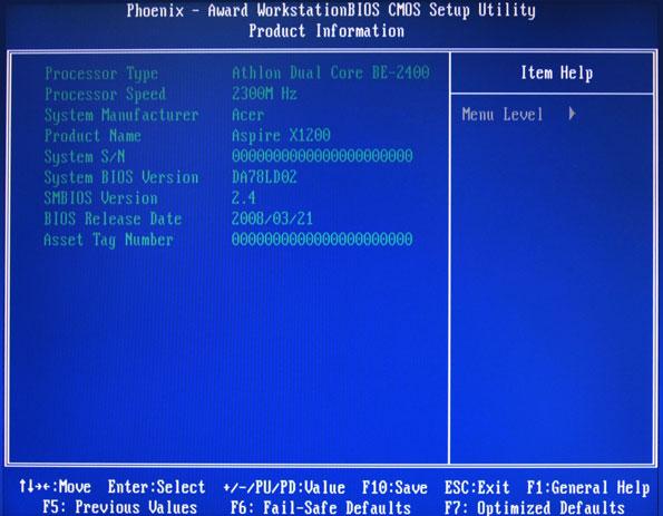
The Product Information menu displays basic information about the system. These entries are for your reference only and are not user-configurable.
Parameter Description Option
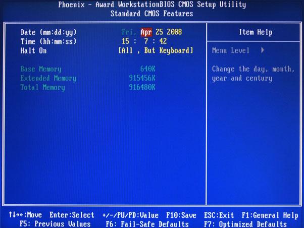
Date Set the date following the weekday-month-day-year format. Time Set the system time following the hour-minute-second format. Halt On Determines whether the system will stop for an error during the POST. All, But Keyboard No Errors All Errors All, But Diskette All, But Disk/Key Base Memory Also called conventional memory. Typically, 640 KB will be reserved for the MS-DOS OS. Extended Memory Total size of extended memory detected during POST Total Memory Total size of system memory detected during POST

Parameter Description
Option
CPU Feature Press Enter to configure the CPU Virtualization and AMD K8 Cool and Quiet Control features. Hard Disk Boot Priority Press Enter to select hard disk boot device priority. Virus Warning Specifies the virus warning feature for IDE hard disk boot sector protection. If enabled, BIOS will show a warning message on the screen or an alarm beep when someone attempts to write data into this area.
Disabled
Enabled CPU Internal Cache Enables or disables CPU internal cache. Enabled Disabled
External Cache Enables or disables internal cache.
Enabled
Disabled
Quick Power On Self Test Allows the system to skip certain test while booting. This will decrease the time needed to boot the system.
Enabled
Disabled
First/Second/Third/Fourth Boot Device Specifies the boot order from the available devices. CDROM, Hard Disk, NVIDIA Boot Age, Floppy, ZIP, USB-FDD, USB-ZIP, USBCDROM, USBHDD, Legacy LAN, Disabled
Boot Up Floppy Seek Enables or disables floppy drive testing to determine whether they have 40 to 80 tracks.
Disabled
Enabled
Boot Up NumLock Status Selects power on state for Num Lock.
Gate A20 Option When set to fast, the motherboard chipset controls the operation of Gate A20. But when set to normal, a pin in the keyboard controller controls Gate A20.
On
Off
Fast
Normal
Typematic Rate Setting When enabled, you can manually adjust the settings using the two typematic controls (Typematic Rate and Typematic Rate Delay). If disabled, the BIOS will use the default setting. Typematic Rate (Chars/Sec) Rate at which the keyboard will repeat the keystroke if you press it continuously. Typematic Delay (MSec) Delay, in Msec, before the keyboard automatically repeats the keystroke that you have pressed continuously.
Disabled
Enabled
6, 8, 10, 12, 15, 20, 24, 30 250, 500, 750, 1000
Parameter
Description
Security Option When set to system, BIOS will ask for the password each time the system boots up. If set to setup, the password is only required for access into the BIOS setup menus.
MPS Version Control For OS Specifies the version of the Multiprocessor Specification (MPS) that the mainboard will use.
OS Select For DRAM > 64 MB Select OS/2 if the system is running OS/2 operating system and the system memory is more than 64 MB in size.
Full Screen Logo Show Enables or disables the display of the full screen boot logo.
Small Logo (EPA) Show Enables or disables the display of the EPA logo.
CPU Feature

Parameter
Description
Virtualization Select whether to enable or disable the AMD Virtualization Technology (VT) function. VT allows a single platform to run multiple operating systems in independent partitions. AMD K8 Cool&Quiet control When set to auto, the AMD Cool’n’Quiet driver dynamically adjust the CPU clock and VIA to reduce heat output from your computer and its power consumption.
Option Setup
System
1.4
1.1
Non-OS/2
OS/2
Enabled
Disabled
Disabled
Enabled
Option Enabled Disabled
Disabled
Auto
The Hard Disk Boot Priority submenu allows you to specify the sequence of loading the OS from the installed hard drives. Use the up or down arrow key to select a hard drive, then press the <+> key or the <-> key to move it up or down on the list. l


Parameter Description Option
Hyper SLI Enable or disable the Scalable Link Interface (SLI) technology. Disabled Enabled iGPU Frame Buffer Control When set to auto, BIOS will automatically setup the frame buffer size. When set to manual, you can set the frame buffer size. Frame buffer size is the total amount of system memory allocated solely for the onboard graphics controller. Frame Buffer Size This parameter can be configured if the iGPU Frame Buffer Control is set to Manual.
Auto
Manual
64, 16, 32, 128, 256 MB CPU Frequency Sets processor minimum and maximum frequency. 200 Minimum 100 Maximum 500 KB<->NB HT Speed Controls the physical speed of the processor to the Northbridge HT link. Auto 200, 400, 600, 800 MHz, 1 GHz
KB<->NB HT Width Controls the processor to the Northbridge link bandwidth.
Auto
Up 8/16 Down 8/16
PCIE Clock Sets the PCI Express clock frequency.
DRAM Configuration Press Enter to configure memory timing and operation settings. CPU Spread Spectrum Allows you to reduce the EMI of the front side bus by modulating the signals it generates so that the spikes are reduced to flatter curves.
PCIE Spread Spectrum Allows you to reduce the EMI of the PCI Express bus by modulating the signals it generates so that the spikes are reduced to flatter curves. When set to down spread, the chipset modulates the PCI Express bus' baseline signal downwards by a small amount. When set to disabled, the chipset disables any modulation of the PCI Express bus' baseline signal. SATA Spread Spectrum Allows you to reduce the EMI of the SATA bus by modulating the signals it generates so that the spikes are reduced to flatter curves. When set to down spread, the chipset modulates the SATA bus' baseline signal downwards by a small amount. When set to disabled, the chipset disables any modulation of the SATA bus' baseline signal.
100
Minimum 100 Maximum 200
Disabled
-0.5%, 1.0%
Disabled
Down Spread
Disabled
Down Spread
Parameter Description
Option
iGPU Spread Spectrum Allows you to set the integrated GPU spread spectrum. 50 Triangular Cntr 100/200/300 Triangular Cntr SSE/SSE2 Instructions Enables or disables the processor’s SSE and SSE2 instruction sets. Enabled Disabled MCP78 PCIE Training Cards supporting Gen2 mode will be trained in Gen2 mode. Gen2 if supported Only Gen1
System BIOS cacheable Enables or disables the caching of the mainboard BIOS ROM from F0000h to FFFFFh by the processor’s Level 2 cache.
Disabled
Enabled
Parameter
Description
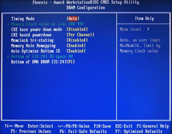
Timing Mode When set to auto mode, the system reads the electronic data sheet of the memory modules and adjusts the timings accordingly. When set to MaxMemClk, you can manually specify the memory clock frequency independent of the system bus frequency. Memory Clock value or Limit Displays the current memory clock frequency. CKE base power down mode All synchronous memory devices can go into sleep mode as soon as the clock enable (CKE) signal is disasserted. In that case, the internal clocks are disabled and the memory chip goes into auto-refresh mode which is the lowest power state at which the memory retains data. If then power is turned off, the device will lose all data, however, as long as standby power is maintained, no data loss will occur. CKE based power down Sets the CKE power saving through disasserting clock enable using system level or per channel basis.
Option Auto
MaxMemClk
Disabled Enabled
Per Channel
Per CS
Memclock tri-stating Enables or disables the memory clock tri-stating during C3 an Alt VD feature.
Disabled
Memclock tristating during C3 and Alt VD Memory Hole Remapping Enables or disables memory remapping around the memory hole. Enabled Disabled
Auto Optimize Bottom IO Allows you to auto optimize maximal memory size when kernel assigns PCI Resources.
Enabled
Disabled
Bottom of UMA DRAM [31:24] [FC] Allows you to enter a HEX number ranging from 0000 to 00F0.
Minimim 0000
Maximum 00FC

Parameter Description Option
IDE Function Setup Press Enter to access the IDE Function Setup submenu. MCP Storage Config Press Enter to access the MCP Storage Config submenu. Init Display First Select whether to boot the system using the AGP graphic card or a PCI card installed on the PCI Express slot or PCI slot.
PCIEx PCI Slot Onboard HD Audio Enables or disables the onboard audio controller. Auto Disabled HDMI Audio Allows you to control the audio function of the onboard HDMI. Disabled Auto
MAC LAN Enables or disables the built-in network interface card.
Auto
Disabled
IDE HDD Block Mode When enabled, the BIOS will automatically detect if your hard disk supports block transfers and set the proper block transfer settings for it. Depending on the IDE controller, up to 64 KB of data can be transferred per interrupt when block transfers are enabled. When disabled, only 512 bytes of data can be transferred per interrupt.
Enabled
Disabled
Onboard Serial Port 1 Select the I/O address and IRQ for the first serial port. 3F8/IRQ4 2F8/IRQ3 3E8/IRQ4 2E8/IRQ3 Auto Disabled Onboard Parallel Port Select the I/O address and IRQ for the onboard parallel port. 378/IRQ7 278/IRQ5 3BC/IRQ7 Disabled
Parallel Port Mode Select an operating mode for the onboard parallel port.
ECPM Mode Use DMA Select DMA channel for the LPT port in ECP mode. This parameter can be configured if the parallel port mode is set to ECP or ECP +EPP mode. USB Device Setting Press Enter to access the USB Device Setting submenu.
SPP
EPP ECP ECP+EPP
3
1

Parameter
Description OnChip IDE Channel 0 Enables or disables the first IDE channel.
Primary Master PIO
Primary Slave PIO When set to Auto, BIOS setup automatically detects if the installed hard disk supports the function. If supported, it allows for faster data recovery and read/write timing that reduces hard disk activity time. This results in better hard disk performance. Mode 0 to 4 provide progressive increase of performance.
Option Enabled
Disabled
Auto
Mode 0 Mode 1 Mode 2 Mode 3 Mode 4
Auto
Mode 0 Mode 1 Mode 2 Mode 3 Mode 4
Primary Master UDMA
Primary Slave UDMA Enables or disables the primary and master UDMA mode
Auto
Disabled
Auto
Disabled
IDE DMA Transfer Enables or disables DMA (Direct Memory Access) transfers for all IDE drives.
Enabled
Disabled Serial-ATA Controller Enables or disables the serial ATA controller. Enabled Disabled IDE Prefetch Mode Enables or disables the IDE controller to prefetch data from the IDE drive. Enabled Disabled

Parameter
Description
SATA Operation Mode Select a SATA operation mode.
SATA 0 -- Port 1 ~ 6 Enables or disables the SATA RAID on ports 1 to 6. This parameter can be configured if the SATA Operation Mode is set to RAID
Option AHCI
IDE RAID Linux AHCI
Disabled
Enabled
SATA SALP Feature Select a Supports Aggressive Link Power Management (SALP) feature. Off Partial Slumber
Parameter
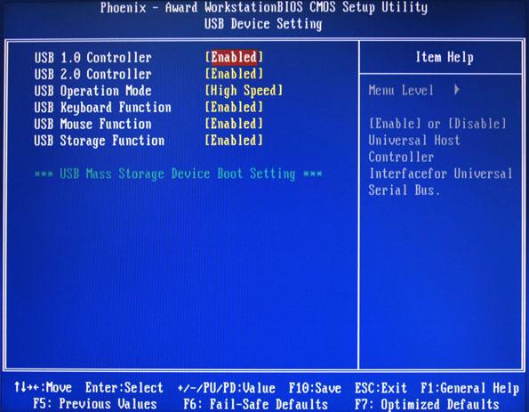
USB 1.0 Controller
Description
USB 2.0 Controller Enables or disables the onboard USB controller.
USB Operation Mode Select a USB device operation speed.
USB Keyboard Function Enables or disables legacy support of the USB keyboard.
USB Mouse Function Enables or disables legacy support of the USB mouse.
USB Storage Function Enables or disables legacy support of the USB storage device.
Option Enabled
Disabled
Enabled
Disabled
High Speed
Full Low Speed
Enabled
Disabled
Enabled
Disabled
Enabled
Disabled

Parameter
Description
ACPI function Enables or disables the Advanced Configuration and Power Management (ACPI) function.
Option Enabled
Disabled
ACPI Suspend Type Select an ACPI state.
Power Management Select a power saving method for the following modes: • HDD power down • Suspend mode
S1 & S3
S1 (POS) S3 (STR)
User Define
Min. Saving Max Saving
Video Off Method Determines the manner when the monitor goes blank.
DPMS Support
Blank Screen V/H Sync + Blank
HDD Power Down Set a time when the hard disk drives will power down after a period inactivity.
Disabled
1 to 14 Min HDD Down in Suspend Enables or disables the HDD power down function in suspend mode. Disabled Enabled Soft-Off by PBTN Determines the behavior of system power button. Instant-Off Delay 4 Sec PowerOn After Pwr-Fail Set the system to automatically start itself up after a power failure. Off On Former-Sts
WOL (PME#)/From Soft-Off Enables or disables to wake up the system from a power saving mode through an event on a LAN device or using soft-off.
Disabled
Enabled
S5 Resume by USB If enabled, press any key or click the mouse will wake system from S1/ S3 state.
Disabled
Enabled Power-On by Alarm Enables or disables to boot the system on scheduled date/time. Disabled Enabled
Day of Month Alarm Time (hh:mm:ss) Alarm This parameter can be configured if the Power-On by Alarm is set to enable. HPET Support Enables or disables the High Precision Event Timer (HPET) function. Enabled Disabled
PS2 KB Wakeup Enables or disables to wake up the system from a power saving mode using a PS2 keyboard.
PS2 Mouse Wakeup Enables or disables to wake up the system from a power saving mode using a PS2 mouse.
Disabled
Enabled
Disabled
Enabled

Parameter
Description
Reset Configuration Data If enabled, the system is forced to update Extended System Configuration Data (ESCD) and then is automatically set to the disabled mode. If disabled, the system ESCD will update only when the new configuration varies from the last one. Resources Controlled By When set to auto ESCD, the system BIOS will detect the system resources and automatically assign the relative IRQ and DMA channel for each peripheral. When set to manual, you have to assign the IRQ and DMA for add-on cards.
Option Disabled
Enabled
Auto ESCD
Manual
IRQ Resources This parameter can be configured if the Resources Controlled By is set to Manual. It allows you to assign each system interrupt a type, depending on the type of device using the interrupt.
IRQ-5
IRQ-7, IRQ-9, IRQ-10, IRQ-11, IRQ-14
PCI/VGA Palette Snoop Enables or disables the system graphic card to allow VGA palette snooping.
Disabled
Enabled Maximum Payload Size Set the maximum payload size for Transaction packets (TLP). 4096 128, 256, 512, 1024 2048

Parameter
Description
Smart FAN Control Enables or disables the smart system fan control function.
Shutdown Temperature Set the CPU shutdown temperature.
Option Enabled
Disabled
Disabled
60C/140F ° ° 65C/149F ° ° 70C/158F ° °
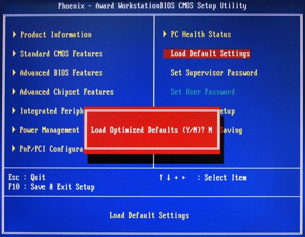
The Load Default Settings menu allows you to load the default settings for all BIOS setup parameters. Setup defaults are quite demanding in terms of resources consumption. If you are using low-speed memory chips or other kinds of low-performance components and you choose to load these settings, the system might not function properly.
The Set Supervisor Password menu allows you to set a supervisor password. The supervisor password allows you to access and change all settings in the Setup Utility.
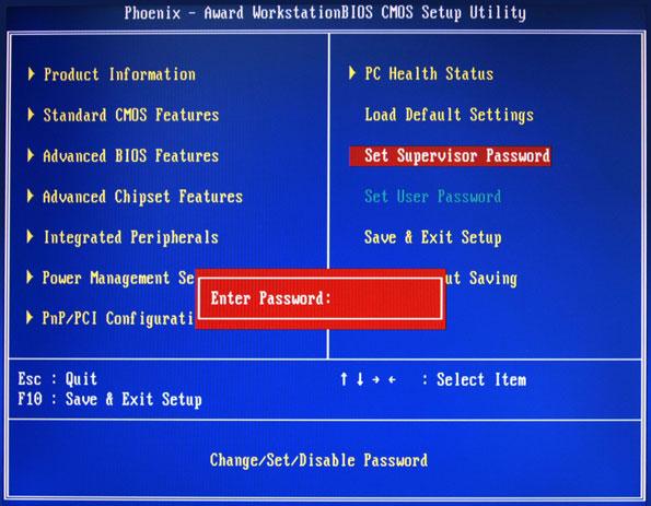
Setting a supervisor password
1. Use the up/down arrow keys to select Set Supervisor Password menu then press Enter.
A password box will appear. 2. Type a password then press Enter.
The password may consist up to six alphanumeric characters (A-Z, a-z, 0-9) 3. Retype the password to verify the first entry then press Enter again. 4. Press F10. 5. Select Yes to save the new password and close the Setup Utility.
Changing the supervisor password
1. Use the up/down arrow keys to select Set Supervisor Password menu then press Enter. 2. Type the original password then press Enter. 3. Type a new password then press Enter. 4. Retype the password to verify the first entry then press Enter again. 5. Press F10. 6. Select Yes to save the new password and close the Setup Utility.
Removing a supervisor password
1. Use the up/down arrow keys to select Set Supervisor Password menu then press Enter. 2. Enter the current password then press Enter. 3. Press Enter twice without entering anything in the password fields.
The Set User Password menu allows you to set a user password. Entering this password will restrict a user’s access to the Setup menus. A supervisor password must be set first before you can enable or disable this field. A user can only access and modify the system time, system date, and set user password.
Setting a user password
1. Use the up/down arrow keys to select Set User Password menu then press Enter.
A password box will appear. 2. Type a password then press Enter.
The password may consist up to six alphanumeric characters (A-Z, a-z, 0-9) 3. Retype the password to verify the first entry then press Enter again. 4. Press F10. 5. Select Yes to save the new password and close the Setup Utility.
Changing the user password
1. Use the up/down arrow keys to select Set User Password menu then press Enter. 2. Type the original password then press Enter. 3. Type a new password then press Enter. 4. Retype the password to verify the first entry then press Enter again. 5. Press F10. 6. Select Yes to save the new password and close the Setup Utility.
Removing a user password
1. Use the up/down arrow keys to select Set User Password menu then press Enter. 2. Enter the current password then press Enter. 3. Press Enter twice without entering anything in the password fields.
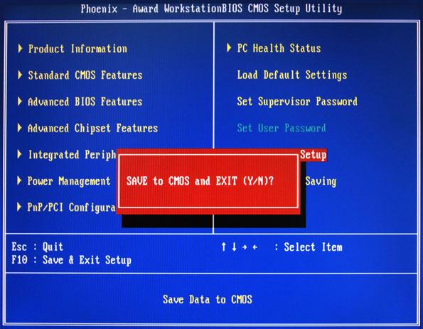
The Save & Exit Setup menu allows you to save changes made and close the Setup Utility.
The Exit Without Saving menu allows you to discard changes made and close the Setup Utility.