2 minute read
LCD Disassembly


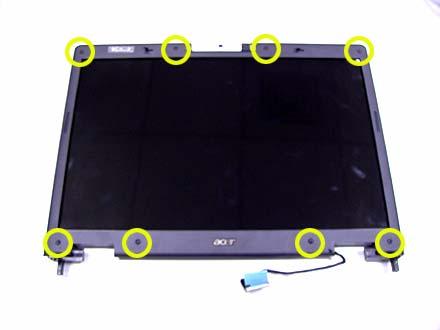
1. Remove the eight rubber caps on the LCD bezel and release the eight screws securing the
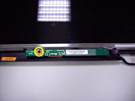
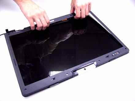
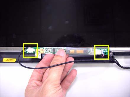
LCD bezel. 2. Detach the LCD bezel from the LCD module as shown. 3. Release the screw holding the inverter board. 4. Disconnect the inverter board cables as shown and remove the inverter board.
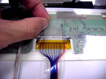
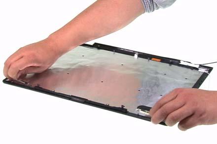
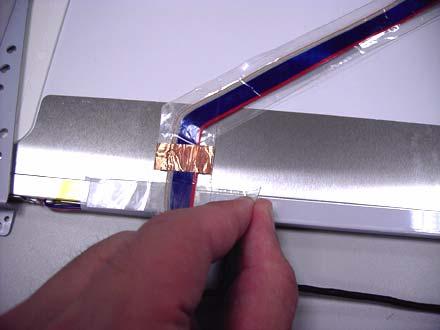
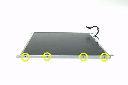
5. Release the four screws securing the LCD panel. 6. Detach the LCD panel carefully and reverse it as shown. 7. Tear off the tapes holding the LCD panel cable carefully then disconnect the LCD panel. 8. Remove the antenna from the LCD cover.
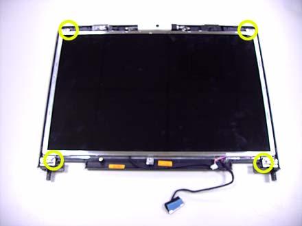
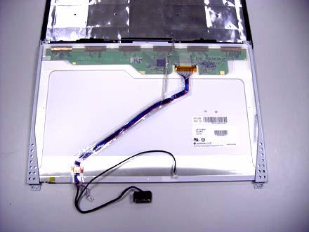
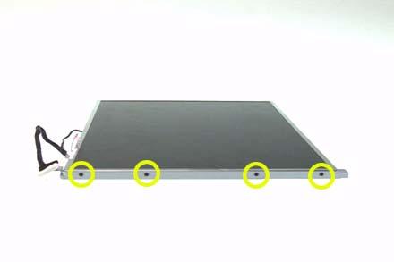
9. Release the four screws securing the left LCD bracket then remove the left LCD bracket. 10. Repeat the anterior step to remove the right LCD bracket.
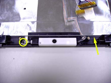
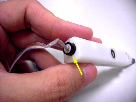
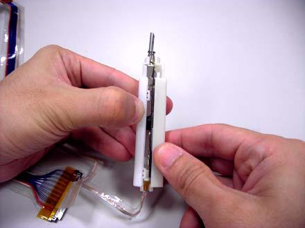
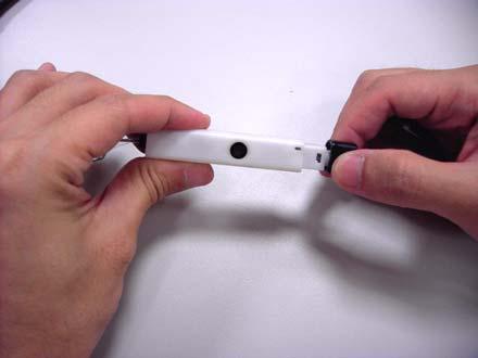
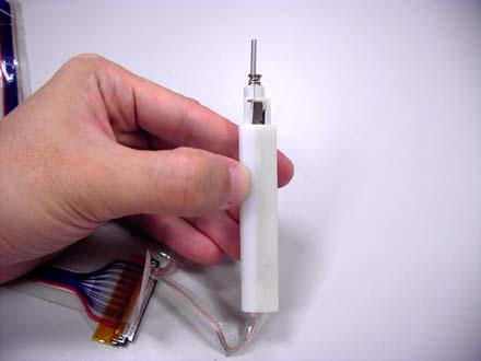
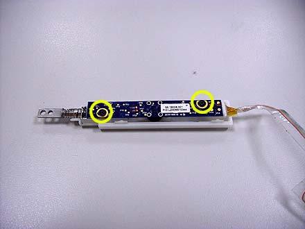
11. Release the screw holding the CCD module and carefully pull the CCD module cable and LCD cable through the latch bar and LCD cover. 12. Remove the CCD module cap. 13. Remove the CCD module ring. 14. Push the CCD module upper case a little bit. 15. Then Separate the lower case from the upper case. 16. Release the two screws holding the CCD module board the detach the CCD module board.
Troubleshooting
Please use the following procedures as a guide for computer problems.
NOTE: The diagnostic tests are intended to test only Acer products. Non-Acer products, prototype cards, or modified options may occur errors or invalid responses. 1. Obtain the detailed fail symptoms as many as possible. 2. Verify the symptoms by attempting to recreate, running the diagnostic tests or repeating the same operation. 3. Disassemble and assemble the unit without any power sources. 4. If any problem occurs, you can perform visual inspection before you fellow this chapter’s instructions. You can check the following: Power cords are properly connected and secured; There are no obvious shorts or opens; There are no obviously burned or heated components; All components appear normal.


