3 minute read
Disassembling the Main Unit


Separating the Upper Case and the Lower Case
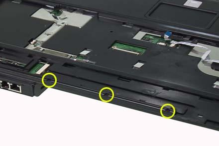
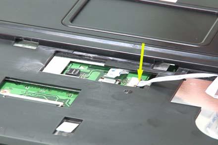
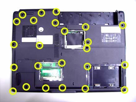
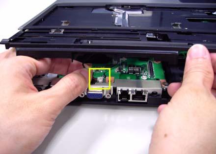
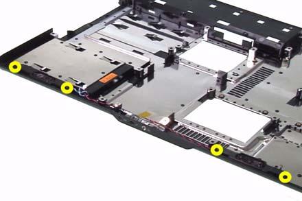
1. Release the connector lock and disconnect the touch pad FFC. 2. Release the connector lock and disconnect the function keyboard FFC. 3. Release the three screws securing the upper case. 4. Release the 27 screws holding the lower case. 5. Lift the upper case carefully and disconnect the lid switch cable. 6. Then separate the upper and the lower case.


Removing the Function Keyboard
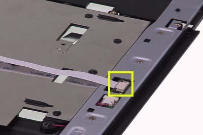
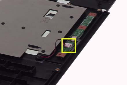
1. Release the FFC lock and disconnect the function keyboard FFC. 2. Release the four screws holding the function keyboard bracket. 3. Then remove the function keyboard bracket. 4. Carefully disconnect the microphone cable and remove the function keyboard.


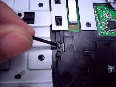
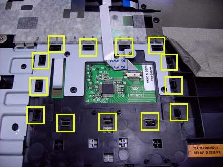
Removing the Touch Pad Board
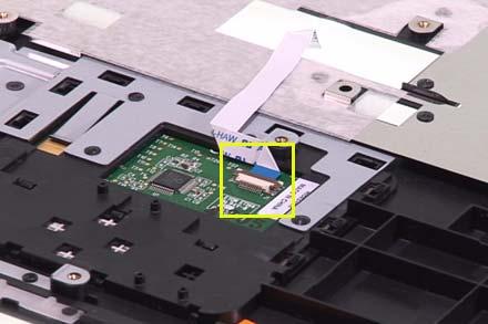
1. Carefully release the FFC lock and disconnect the touch pad board FFC. 2. There are 13 latches holding the touch pad bracket. 3. Unlock those latches with a screw driver as shown then detach the touch pad bracket. 4. Detach the touch pad board.

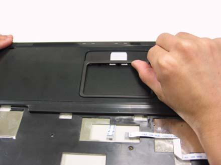
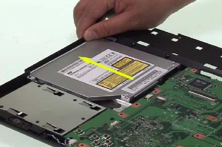
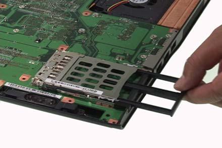
Removing the ODD Module and Dummy Card
1. Slightly pull the ODD module and remove it. 2. Pull the dummy card from the slot and remove it.
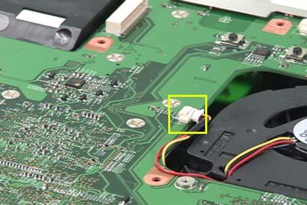
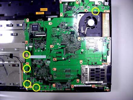
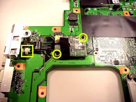
Removing the Main Board
1. Disconnect the fan cable. 2. Disconnect the speaker cable and Bluetooth module cable. 3. Remove the four screws securing the main board. 4. Then detach the main board from the lower case.


Removing the System Fan


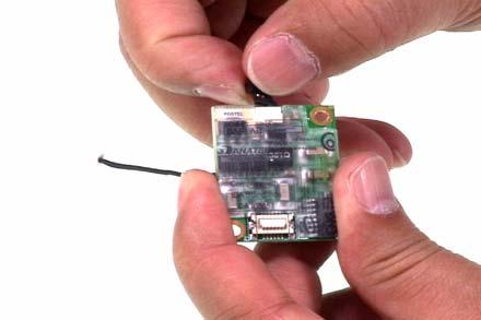
Removing the Bluetooth Module
1. Detach the bluetooth module from the lower case. 2. Carefully disconnect the bluetooth module cable.
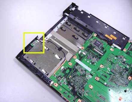
Removing the Speakers
1. Release the four screws securing the left and right speakers. 2. Remove the speakers from the lower case.
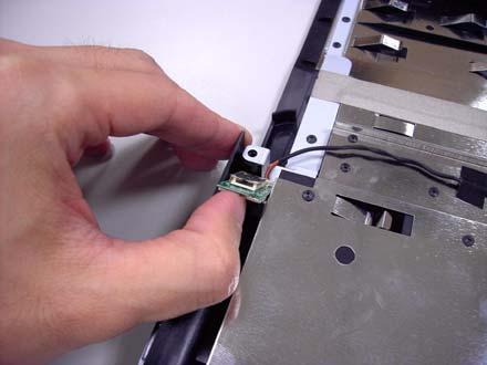
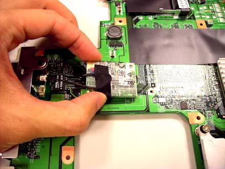
Removing the MDC Module
1. Carefully disconnect the MDC cable. 2. Release the two screws securing the MDC board then detach the MDC board. 3. Disconnect the MDC board cable.

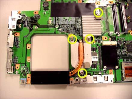
Remove the Heatsink Module
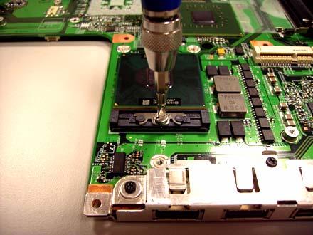
Removing the CPU
1. Release the screw counter clockwise with a flat screw driver. 2. Detach the CPU from the CPU socket.