7 minute read
System Utilities


BIOS Setup Utility
The BIOS Setup Utility is a hardware configuration program built into your system’s BIOS (Basic Input/Output System). Since most systems are already properly configured and optimized, there is no need to run this utility. The BIOS setup utility stores basic settings for your system. You will need to run this utility if you encounter configuration problems. Refer to Chapter 4 Troubleshooting when problem arises.
Entering BIOS Setup
Power on the system to start the system POST process. During bootup, press F2 to enter the BIOS setup screen. NOTE: You must press F2 while the system is booting. This key does not work during any other time.
BIOS Setup Primary Menus
There are several tabs on the setup screen corresponding to the six primiary BIOS menus. Information Main Security Boot Exit In the descriptive table following each of the screen illustrations, settings in boldface are the default and suggested parameter settings.
BIOS Setup Navigation Keys
Note the following reminders when moving around the Setup utility. Use the Left and Right arrow keys to move to the next page or to return to the previous screen. Use the Up and Down arrow keys to select an item. Use the + and - keys to select an option. NOTE: You can configure a parameter that is enclosed in square brackets. Grayed-out items have fixed settings and are not user-configurable. Use the Enter key to display a submenu screen. NOTE: When a parameter is preceeded by an arrow or (>), it means that a submenu screen is available. Press F1 for General Help using the BIOS setup. Press F9 to load the default configuration. Press F10 to save changes and close the BIOS setup. Press Esc to close the BIOSe setup. NOTE: The parameters on the screens shown in this Guide display default system values. These values may not be the same as those in the system. System information is subject to different models.
Parameter Description
CPU Type Type of processor currently installed in the system. CPU Speed Speed of the processor currently installed in the system. IDE0 Model Name Model name of HDD installed on the primary IDE channel. IDE0 Serial Number Serial number of HDD installed on the primary IDE channel. ATAPI Model Name Model name of the ATAPI CD/DVD-ROM drive installed in the system. System BIOS Version Version number of the BIOS setup utility. VGA BIOS Version Version number of the VGA firmware. KBC Version Version number of the keyboard controller. Serial Number Serial number of the system. Asset Tag Number Asset tag number of the system. Product Name Product name of the system. Manufacturer Name Name of the manufacturer of this system. UUID Visible only when an internal LAN device is present. UUID=32bytes
NOTE: The system configuration information varies in different models.
Parameter Description Format/Option
System Time Set the system time following the hour-minute-second format. Format: HH:MM:SS (hour:minute:second) System Date Set the date following the weekday-month-day-year format. Format MM/DD/YYYY (month/day/year) System Memory Total size of system memory detected during POST. Extended Memory Total size of extended memory during POST. Video Memory Total size of VGA memory. Quiet Boot When Enabled, the BIOS splash screen is displayed during startup.
Enabled
Disabled
Network Boot When Enabled, the system can be booted from another PC on your LAN, such as a remote server. F12 Boot Menu When Enabled, pressing the F12 key during POST brings up a menu of devices that you can select to boot. D2D Recovery Enables or disables disk-to-disk recovery. D2D recovery is a method of restoring the system to factory configurations without using recovery CDs.
Enabled
Disabled Disabled
Enabled Enabled
Disabled
Parameter Description Option
Supervisor Password Is Indicates whether a supervisor password has been assigned. User Password Is Indicates whether a user password has been assigned. HDD Password Is Indicates whether a hard disk drive password has been assigned. Clear or Set
Clear or Set
Clear or HDD Password Set
Set Supervisor Password Press Enter to configure the supervisor password. Set User Password Press Enter to configure the user password. Set HDD Password Press Enter to configure the hard disk drive password. Password on Boot Enables or disables security check during POST. Disabled or Enabled
NOTE: Refer to the “Removing a System Password” on page 39 for more information on how to remove a password.
1. Use the up/down keys to select a password parameter, then press Enter. A Password box appears. 2. Type a password then press Enter.
The password may consist of up to six alphanumeric characters (A-Z, a-z, 0-9). 3. Retype the password to verify the first entry then press Enter again. You will be prompted to save the new password. 4. Press Enter. 5. Press F10 to save the password and close the Setup Utility.
Changing a System Password
1. Use the up/down keys to select a password parameter , then press Enter. 2. Type the original password then press Enter. 3. Type a new password then press Enter. 4. Retype the password to verify the first entry then press Enter. 5. Press Enter. 6. Press F10 to save the new password and close the Setup Utility.
Removing a System Password
1. Use the up/down keys to select a password parameter, then press Enter. 2. Enter the original password then press Enter. 3. Press Enter twice without entering anything in the new and confirm password fields. 4. Press Enter. After doing this, the system automatically sets the related password parameter to Clear. 5. Press F10 to save the new password and close the Setup Utility.
Clearing the Supervisor or User Password
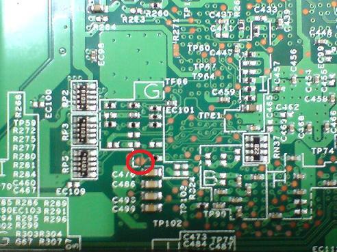
If the Password on Boot field have been enabled and you forgot the BIOS password (supervisor/user password), you will not be able to boot up the system. You need to clear the lost password by shorting the hardware gap located near the DIMM slot. 1. Power off the system. 2. Unplug the adapter and power cable. 3. Remove the battery pack. See “Removing the Battery Pack” on page 49. 4. Remove the lower cover. See “Removing the Lower Cover” on page 50. 5. If necessary, remove the memory module. See “Removing the DIMM” on page 51.
Hardware gap Default setting Operation Description
G67 Open (Normal) Short to clear supervisor and user password.
7. Using an electrical conductivity tool, short the two contacts on the hardware gap together. 8. While resting the tool on the two contacts, plug one end of the AC adapter into the DC-in jack and plug one end to an electrical outlet. 9. Press the power button to turn on the system. 10. After BIOS POST message, remove the tool from the hardware gap. 11. Reinstall the memory modules and lower cover. 12. Restart the system and press <F2> during the bootup to enter the BIOS setup screen. 13. Repeat above procedure if the BIOS password is not cleared.
This menu allows you to set the drive priority during system boot-up. The system will attempt to boot from the first device on the list. If the first device is not available, it will continue down the list until it reaches an available device. BIOS setup will display an error message if the drive(s) specified is not bootable.
Parameter Description
Exit Saving Changes Save changes made and close the BIOS setup. Exit Discarding Changes Discards changes made and close the BIOS setup. Load Setup Defaults Loads the default settings for all BIOS setup parameters. Setup Defaults are quite demanding in terms of resources consumption. If you are using low-speed memory chips or other kinds of low-performance components and you choose to load these settings, the system might not function properly. Discard Changes Discards all changes made in the BIOS setup. Save Changes Saves changes made in the BIOS setup.
If BIOS flash procedure fails in your system, perform a BIOS recovery procedure by using the crisis recovery diskette. During this procedure, the system will force BIOS to load and execute a special BIOS block (also called boot block) to restore the BIOS code from the crisis recovery diskette. Note the following when restoring the BIOS settings: Use the <Fn> + <Esc> hotkey to enable BIOS recovery during BIOS POST.
Important: When using the <Fn> + <Esc> hotkey to enable BIOS recovery, we strongly recommend the following: Make sure the battery pack is installed to the system. Make sure the adapter is connected to the system and plugged into a wall outlet. A crisis recovery diskette should be prepared in Windows XP/Vista. Perform the following procedure to restore BIOS: 1. Power off the system. 2. Connect a USB floppy drive to the system. 3. Insert the Crisis Disk to the floppy drive. 4. Press and hold <Fn> + <Esc> keys, then press the power button.
The system initializes the BIOS recovery process. The boot block BIOS starts to restore the failed BIOS code from the crisis recovery diskette. Once the process is completed, the system will restart.
After a successful BIOS recovery procedure. RD/CSD can update the BIOS by regular BIOS flashing procedure.