7 minute read
Monitoring System


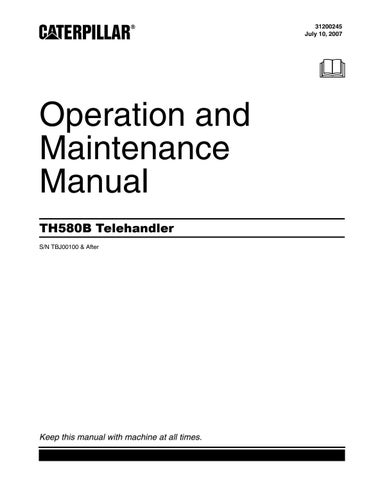
Broom
Illustration 118 g01015331 Refer to the approprite service manual for more information.
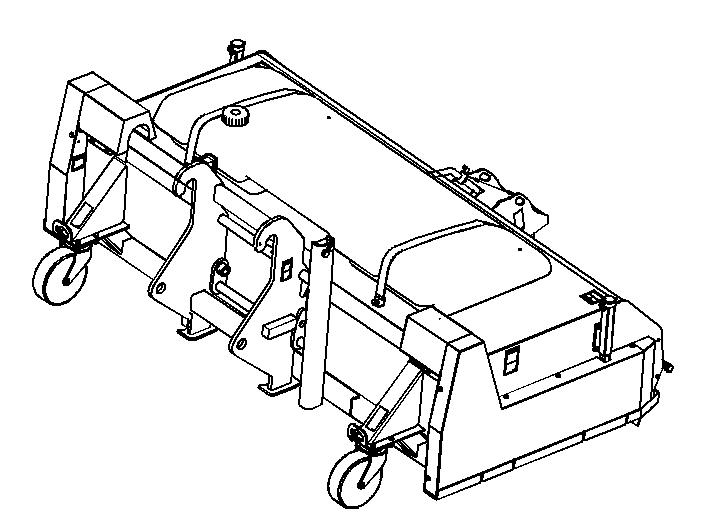
Monitoring System Alert Indicators
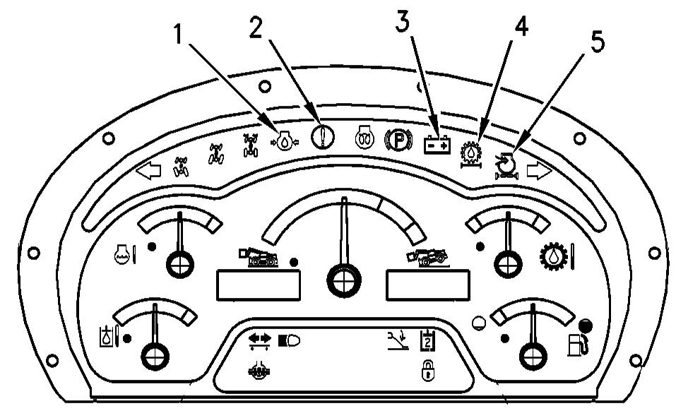
Illustration 119 g01002552 Engine Oil Pressure (1) -This indicator illuminates when the engine oil pressure is low.
Action Lamp (2) -This indicator will illuminate when a failure that is a warning category 2 or a higher warning occurs. If the lamp is illuminated, the machine needs to be serviced soon. The color of this indicator can be amber or red. An audible alarm may also sound when this indicator is illuminated. When a warning category 2 occurs, the action lamp flashes red and there is no audible alarm. In order to prevent severe damage to components, the operator is required to change the machine operation or the operator is required to perform maintenance to the machine. When a warning category 2S occurs, the action lamp flashes red and there is a constant audible alarm. In order to prevent severe damage to components, the operator is required to change the machine operation. When a warning category 3 occurs, the action lamp flashes red and there is an intermittent audible alarm. In order to prevent personal injury or severe damage to components, the operator is required to perform a safe engine shutdown. When the machine has been configured with no model designation, indicator (2) flashes amber and no audible alarm will sound. This condition will not log an error code. When the data link is not communicating with the display unit, indicator (2) flashes amber and no audible alarm will sound. This condition will log an error code. Battery Condition (3) - This indicator illuminates when the battery is not receiving a charge from the alternator.
Combined Transmission and Hydraulic Oil
Filter (4) - This indicator illuminates when the transmission oil filter needs to be. Engine Air Filter (5) - This indicator illuminates when the engine air filter needs to be replaced.
Indicators
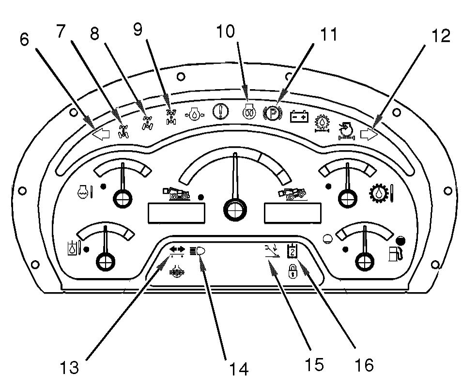
Illustration 120 g01014331
Left Turn Signal (6) - This indicator flashes when the left turn signal is operating.
Circle Steer (7) - This indicator is illuminated when circle steer mode is selected.
Crab Steer (8) - This indicator is illuminated when crab steer mode is selected.
Engine Starting Aid (10) - This indicator is illuminated when the engine starting aid is switched on. Parking Brake Indicator (11) - This indicator illuminates when the parking brake is engaged.
Right Turn Signal (12) - This indicator flashes when the right turn signal is operating.
Trailer Turn Signals (13) - This indicator flashes when a trailer turn signal is operating.
High Beam (14) - This illuminates when the high beam headlights are switched on.
Stabilizers (15) - This light indicates when the stabilizers are lowered.
Hydraulic Auxiliary 2(16) -This indicates when the solenoids on the diverter valve have been energized in order to divert oil flow to the second auxiliary circuit.
Gauges
These gauges are used to help the operator to monitor trends in machine operation or changes in machine operation.
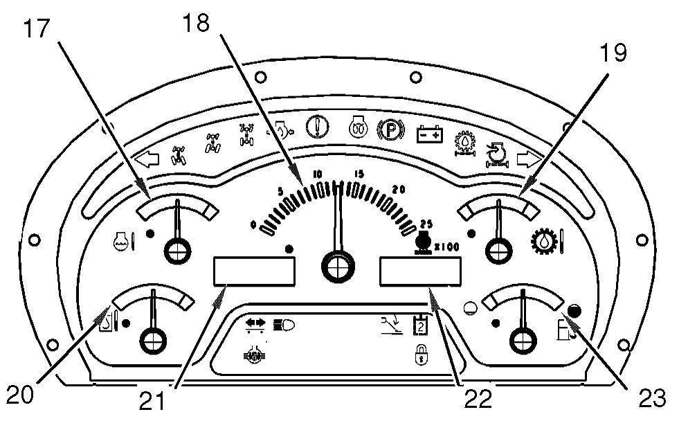
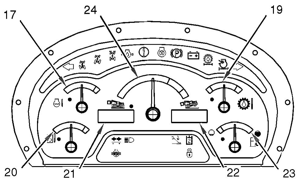
Illustration 121 g01014333 Display panel with tachometer Engine Coolant Temperature (17) - This gauge indicates the temperature of the engine coolant. The green zone indicates that the engine coolant temperature is normal. The red zone indicates that the engine coolant is overheating. If the gauge indicates overheating, stop the engine. Investigate the cause. Check the coolant level. Check that the fan drive belt is not broken or loose. Check that the radiator fins are clean. Tachometer (18) - This gauge indicates the speed of the engine in revolutions per minute, if equipped. Refer to Illustration 121. Torque Converter Oil Temperature (19) -This gauge indicates the temperature of the transmission and hydraulic system oil after the oil has passed through the torque converter. The green zone indicates that the temperature of the transmission and hydraulic system oil is normal. The red zone indicates that the torque converter temperature is overheating. Speedometer (21) - This digital display indicates the current speed of the machine. Service Hour Meter (22) - This digital display indicates the total operating hours of the engine. The service hour meter should be used to determine the service hour maintenance intervals. Hydraulic Oil Temperature (20) - This indicates the temperature of the transmission and hydraulic system oil in the sump. The green zone indicates that the temperature of the transmission and hydraulic system oil temperature is normal. The red zone indicates that the transmission and hydraulic system oil is overheating. Fuel Level (23) - This gauge indicates the amount of fuel that is left in the fuel tank. When the needle on the fuel gauge reaches the red area the fuel tank should be filled. Longitudinal Stability Indicator (24) - This gauge indicates the longitudinal stability of the machine, if equipped. Refer to Illustration 122. Refer to "Longitudinal Stability Indicator" for more information.
Longitudinal Stability Indicator
Operating the machine beyond its stability limit could result in a tip over or failure of the work tool. Check the proposed lift with the load chart. Do not attempt the lift if the longitudinal stability limit of the machine will be exceeded. Tip over or failure of the work tool could cause personnel injury or death.
Your machine may be equipped with a longitudinal stability indicator. The longitudinal stability indicator provides audible signals and visual signals in order to indicate the limit of the forward stability of the machine, if equipped. The audible signal is shared with other system failures. Refer to Operation and Maintenance Manual for usages of the audible signal. The longitudinal stability indicator is powered by the machine electrical system which is activated when the engine start switch key is turned to the ON position. Ensure that a Caterpillar work tool is attached to the machine and use the correct load chart in order to verify that the intended lift operation is within the capability of the machine. Refer to Operation and Maintenance Manual, "Lifting Capacities" for the location of the load charts. The forward stability of the machine will depend on the following factors: • Weight of the attachment • Weight of the load • Angle of the boom • Length of the boom • The position of the stabilizers (if equipped)
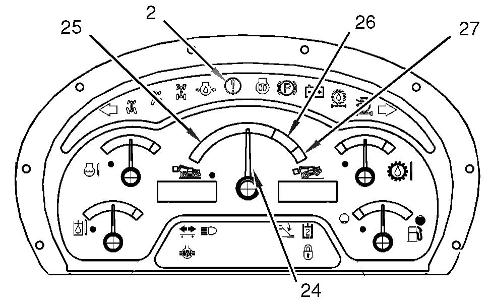
Illustration 123 g01014337
The longitudinal stability indicator has a variable gauge (24) that indicates the longitudinal stability of the machine. The indicator shows the status of the attempted lift operation in comparison to the limit of the machine stability. The variable gauge is located in the center of the display panel. As the load on the machine increases, the indicator moves through the green zone toward the red zone of the gauge. The scale on the gauge has three colored zones. Green Zone (25) - The machine is operating within the limit of forward longitudinal stability. Amber zone (26) - The limit for the forward longitudinal stability of the machine has been reached or exceeded. Red zone (27) - The limit for the forward longitudinal stability of the machine has been exceeded. When the visual indicator (24) enters the amber zone an audible alarm will sound continuously and a visible warning lamp (2) will begin to light. This audible signal indicates that the limit of longitudinal stability has been reached or exceeded. When this condition occurs, do not proceed with the lift operation. Retract the boom if the boom is extended. If the boom is retracted, return the load to the original position. If the indicator is not in the amber zone or the red zone, the alarm may be caused by another system. Check the other gauges for the indication of other problems. Change the operation of the machine.
Extending the boom or lowering a raised boom further increases the outreach of the load. This can reduce the forward stability of the machine. Machine tip over could result. If the longitudinal stability indicator shows that the machine stability limit is being approached, do not lower or further extend the boom. Retract the boom before lowering. Machine tip over could cause personal injury or death to the operator or other personnel in the work area.
The visual indicator (24) and the audible alarm may operate momentarily when the machine is traveling with a load on the work tool. This may occur more frequently on uneven ground or rough terrain. Turning the steering system onto the full lock may also cause unexpected operation of the visual alarm and the audible alarm. When the ignition of the machine is turned from the OFF position to the ON position, the machine will perform the system test for the LSI. Refer to Operation and Maintenance Manual, "Longitudinal Stability Indicator System - Test" for more information. If the system passes the test for the LSI, the machine may be operated as normal. If the LSI system should detect a problem, the machine will fail the system test. This will cause indicator (24) to hold in the red zone (27). An intermittent audible alarm will sound and the warning lamp will be illuminated. Refer to Operation and Maintenance Manual, "Longitudinal Stability Indicator System - Test" for more information if the test fails.