4 minute read
Description of function


Description of function
Set from transport to working position
402275
Step Action Reaction
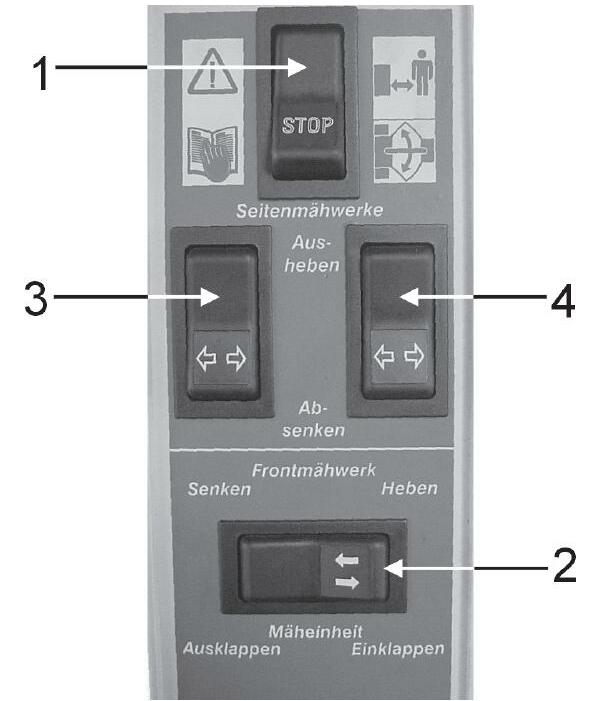
1 Switch 2 on the de-energised is actuated to the right
Solenoid valve 50 switches to position B. Volume flow flows to solenoid valves 71, 72, 73,74. 2 Solenoid valve 72 is energised The applied volume flow flows to cylinder 103. The front mower unit raises to the end position = Pressure rises, oil pressure switch 93 switches at 150 bar
3 Solenoid valves 70 and 71 are energised 4 The displaced volume flow from the ram top spaces flows into the tank via the energised solenoid valve 70. Volume flow flows via solenoid valve 71 into the rod spaces of cylinders 91 and 92. The side-mounted mower units swing in. The lock can be released.
5 Switch 2 on the CCT is actuated to the left Solenoid valve 50 switches to position A. The solenoid valves 70and 71 are energised. This makes volume flow flow through solenoid valves 70: - into cylinders 82 and 85 (also through the non-return valves 81 and 84). - into cylinders 91 and 92. The side-mounted mower units have now swung out and the starting protections are activated
6 The cylinders travel against the limit stop. Pressure switch 95 switches at a pressure of 150 bar.
7 Solenoid valve 72 is energised Volume flow from cylinder 103 flows through 72 and solenoid valve 50 (position A) into the tank. The front mower unit is lowered.
8 The switch console (switch 3) provides the lower command for the left mower unit. Solenoid valve 50 switches to position A Solenoid valve 73 is energised.
9 Volume flow from cylinder 100flows into the tank
10 The switch console (switch 4) provides the lower command for the right mower unit 11 Volume flow from cylinder 90flows into the tank. The left side-mounted mower unit is lowered.
Solenoid valve 50 switches to position ASolenoid valve 74 is energised.
The right side-mounted mower unit is lowered.
38321 When working, the working pressures of all cylinders are supported by accumulators 88, 98 and 102. Below 80 bar, the lock-up valve units are open at switch 94. When the pressure rises above 85 bar, the lock-up valve units are closed and the mower units remain in their position. The ground pressure of the mower units can be read on the pressure gauges 87, 97 and 101.
Raising the entire mower unit
402275
Step Action Reaction
1 The „Raise front attachment” button on the forage harvester is pressed.
Via the 3/3-way solenoid valve in the Jaguar and line 106, volume flow flows into the ram space side of the raise cylinders (110). 2 The mower unit is raised. When a pressure of 85 bar is reached while raising, pressure switch 94 (NO contact) switches.
3 Relays 12 and 15 now cut the power supply to the lock-up valve units 89, 99 and 109.
4 The volume flow displaced from the rod spaces of the cylinder (on the forage harvester) is directed to the cylinders 90 and 100 The lock-up valve units are closed. This is required for keeping all mower units raised when raising the overall mower unit. (The oil does not flow into the accumulators 88, 98 and 102). The cylinders 90 and 100 retract and thus raise the left and right mower units.
5 If the volume capacity of the rod spaces of cylinders 90 and 100 is exhausted, the pressure rises and the pressure switches 96 switch the lockup valve units 89 and 99 so that the excess volume flow is displaced into accumulators 88 and 98. This ensures that no oil can escape from this circuit.
Starting protection
Step Action
1 E.g. when the right mower unit hits an obstacle.
2 When the pressure reaches 180 bar,
3 Volume flow is displaces from the rod space of cylinder 85
Reaction
The pressure in the rod space of cylinder 85 rises.
the pressure relief valve 86 opens.
This volume flow ends up in the rod space of cylinder 90. The right mower unit is raised and swings back.
Set from working to transport position
402275
Step Action
Reaction
1 Switching off the mower unit The mower discs must not rotate any more. 2 Press the "Raise" button on the ground speed control lever (3/3way solenoid valve is energised) until the mower units have no more ground contact. 3 Actuate switch 2 Solenoid valve 72 is energised. Solenoid valve 50 is set to positionB.
4 Volume flow flows into cylinders 103. Cylinders 103 raise the centre mower unit.
5 The cylinders 103 travel to their limit stop. 6 When the pressure reaches 150 bar, the oil pressure switch 93 switches
7 Via the energised solenoid valves 71, volume flow flows into the rod spaces of cylinders 91 and 92. The pressure rises.
The solenoid valves 70 and 71 are energised.
The displaced volume flow flows from the ram top spaces through the energised solenoid valve 70 and from there through the 4/3-way solenoid valve 50B and into the tank. The sidemounted mower unit swing in.